


We Ride Robotics Robobus
Rory Jackson learns about this SAE L4 autonomous passenger vehicle, which is shuttling passengers through multiple cities around the world
The French Open is one of the largest tennis tournaments in the world, held every year at Stade Roland Garros in Paris. The 2024 event ran from May 26 to June 9, with not only a plethora of head-to-heads between elite athletes but, most unusually, a driverless minibus shuttle service for taking VIPs and media to and from the stadium.
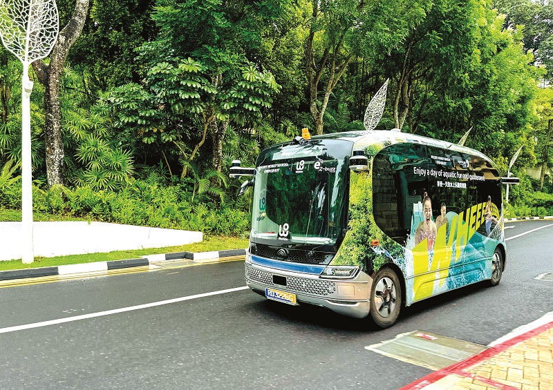
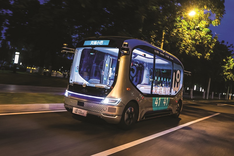
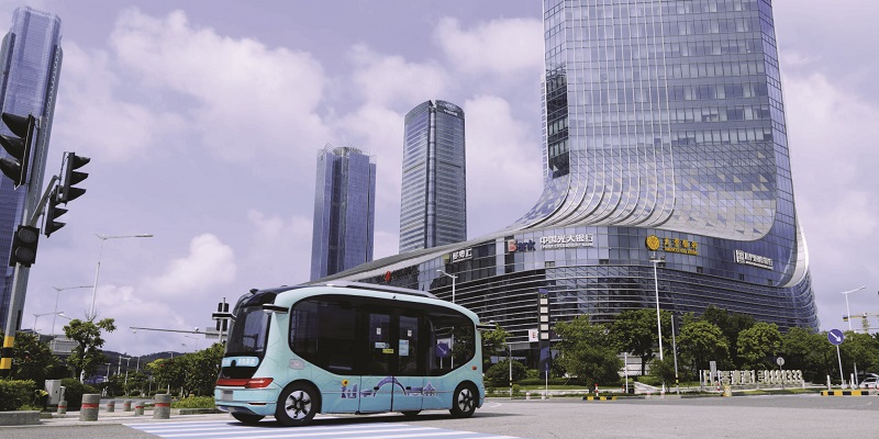
That shuttle was the Robobus, an autonomous passenger transport vehicle, which to date has tested and operated in about 30 cities around the world, including Singapore, Abu Dhabi, Beijing, Guangzhou, and now Paris.
WeRide, an international autonomous driving company with a presence in 30 cities across seven countries, has targeted the SAE’s Level 4 (L4) of driving autonomy in its engineering of the Robobus. This level of intelligence and safety places full responsibility for all driving and navigation on the autonomous system with no need for an onboard driver.
Founded in 2017, with a view towards improving urban living through autonomous systems, WeRide’s original focus was a product called Robotaxi (an autonomous cab). Robotaxi has commercial operations in five cities worldwide and it is still in ongoing development today to achieve safe end-to-end passenger delivery up to speeds of 120 kph.
Its founders, CEO Dr. Tony Han and CTO Dr. Yan Li, gradually encapsulated much of the cab’s technologies into a flexible platform of full-stack application software, infrastructural software and modular hardware, termed ‘WeRide One’. With WeRide One intended for adaptability onto other vehicle types, the pair and their team slowly sought other, more immediately viable products they could develop – particularly ones moving at lower speeds and on more fixed routes to speed up the rate of commercialisation.
As Zhenya Liu, product technology lead at WeRide recounts to us: “In June 2020, Yutong [Zhengzhou Yutong Bus Co., Ltd] contacted us to propose joint development of a self-driving product. We brainstormed several ideas together, but given that Yutong is a world leader in bus manufacturing, the idea for an autonomous minibus felt especially strong in our minds, and so that won out.”
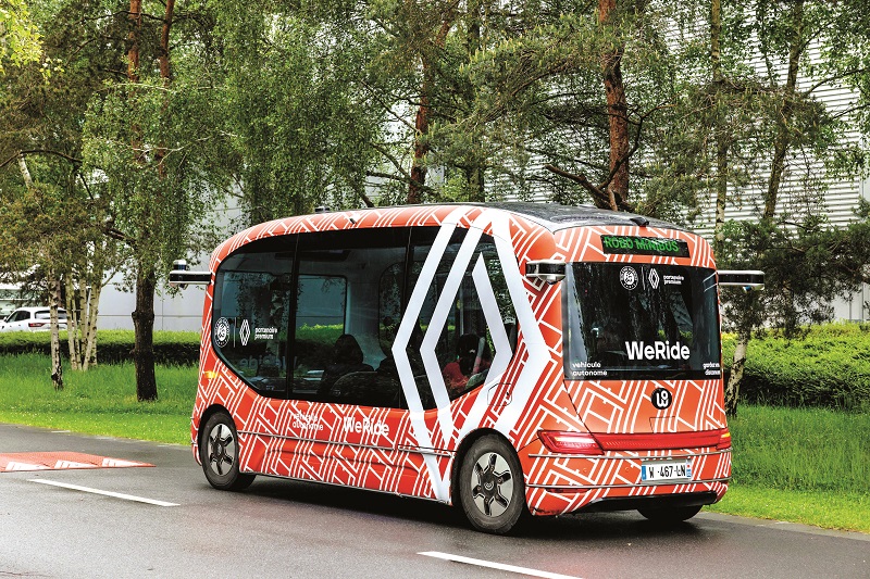
As well as vital input coming from Yutong (as discussed below) to create the Robobus, WeRide’s strategic investors and hence partial owners include the Renault-Nissan-Mitsubishi Alliance, with Renault leadership having played a key part in the Chinese minibus’ recent success in France.
Today, that minibus is a 5.5 m long, 2.6 m tall, 2 m wide, four-wheeled vehicle with a top speed of 40 kph and a minimum turning radius of 5.5 m. It can transport up to 10 seated passengers.
A battery-electric bus, it weighs 4300 kg, achieves typical cruising ranges of 120 km (covering eight-hour operating durations) and it can be fully recharged in one hour on a fast DC charge from a port at its rear right.
To date, Robobuses have accrued nearly three years’ worth of operating hours, and the company notes that its design was the first driverless EV minibus in the world to win the coveted Red Dot award for product and industrial design.
Version 2+
Development work between WeRide and Yutong on the first version of Robobus began in June 2020, using conceptual blueprints that Yutong had already commenced drawing prior to the time. That version’s first prototype rolled off of Yutong’s production line in November 2020, and after some testing, a second version, much closer to the Robobus seen today and far more heavily influenced by WeRide’s engineers, was designed and produced.
On version one’s development, Liu recounts: “It was also in June 2020 that we discussed with Yutong the product positioning and ideal product solutions for installation in the minibus, with Yutong being responsible for engineering the vehicle body and electromechanical control systems, and our team covering the hardware and software for autonomous driving.”
Both companies shared the hefty responsibility of debugging the first prototypes, successfully rolling out the first batch of Robobuses on track for their January 2021 launch date, such that road testing could start and the autonomous driving technologies could be trialled in the real world. Those trials took place in Guangzhou within the defined boundaries of Guangzhou International Biotech Island (the river island on which WeRide’s China offices are headquartered).
Six months of software optimisations followed and, in July 2021, WeRide began trialling the prototypes on public roads (still in its island-based HQ’s surroundings), and demonstrating it for potential partners and customers from Beijing, Wuxi, Nanjing and the UAE. Shipping of trial Robobuses to those locations followed.
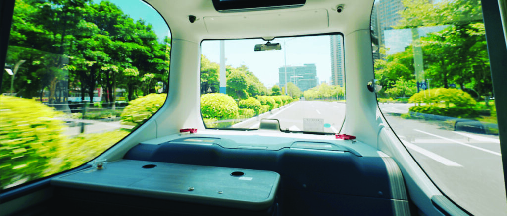
It was soon after that WeRide’s engineers felt confident about a raft of improvements they wanted in the minibus’ design and engineering. They wanted to do away with the safety driver’s seat, steering wheel, brake paddles and related peripherals – a truly L4-grade, self-driving vehicle has no need for such things after all – and they also wanted far larger windows to enhance the comfort and enjoyment of Robobus’ passengers, given the importance of endearing potentially wary customers to the experience of taking self-driving public transport.
“We also wanted the capacity and authorisations needed for higher speeds, which merited adding a lot of redundancies into the vehicle design,” Liu says.
“So, for version two, we added redundant battery power buses, brakes and steering control channels. Also, version one had just two Lidars, and both of those were 16-channel devices. Version two has been redesigned to integrate four more Lidars, and the two main Lidars now function with 64 channels. We’ve also installed 12 HD cameras – that’s probably the biggest single upgrade between Robobus versions one and two.”

Compute systems have also been updated: while version one ran on an Nvidia Xavier-level computer, version two currently uses a proprietary main computer, designed by WeRide to achieve the power, speed and space necessary for its current self-driving algorithms, as well as future expansions and refinements of its AI capabilities.
“We also added infotainment systems, including a voice-control system so that passengers can request some particular music, route information and other things,” Liu notes.
“Getting all these upgrades to work together in a stable package was quite challenging. At a high level, WeRide is a quite new high-tech company, and Yutong is a deeply established and traditional automotive OEM, so we have very different development cultures.
“Yutong is really focused on traceability and certifiability – including writing down basically everything that happens in their facilities – and on engineering via committees and constant meetings to be confident in any decision they make on one of their vehicles.
“As a software-focused company, especially at that time as a startup, WeRide has a simpler report structure and workflow. Being fast to respond, quickly iterative and innovative is our genetic makeup. Therefore, Yutong and WeRide have worked tightly to find the balance, meanwhile discovering that this is also a great practice for mutual complementation.”
On a technical level, adding a wave of new sensors, processing power and redundant systems significantly increased Robobus’ energy consumption, driving the installation of a larger, heavier battery pack. Additionally, the onboard signal network was revamped to cover areas such as the data buses between the main computer and the new infotainment display system, with Yutong and WeRide working closely to define the interfaces between those and other systems, and also to optimise them for simplicity, efficiency and integrity of data carrying.
As well as optimising wireless communications so that remote monitoring and – where necessary – teleoperation can always run smoothly, one of the last items that WeRide added to version two were connectors to quickly plug in or remove a set of steering wheels and brake paddles. The removable steering wheel and brake paddle are designed to give full control of the vehicle, which are used in some situations such as road-testing new traction or steering systems (where running via autonomy or teleoperation are unnecessary), or taking over as a final safeguard in trials of redundant systems should the backups fail to kick in upon the failure or deactivation of the main system.
Thanks to the improvements between Robobus versions one and two, the former’s software-locked speed limit of 15 kph could be increased to 40 kph in the latter, which could also operate in open, public streets, unlike the first version, which was confined to private roads.
“We like to think of today’s Robobus as ‘Version 2+’ as the minibus has stayed mostly the same, with just a few upgrades in terms of Lidar hardware and software algorithms to enhance performance,” Liu says. “But the vehicle body, structure and anatomy has largely stayed the same from version two.”
Shaping Robobus
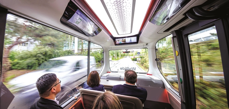
At a high level, the Robobus is designed similarly to other minibuses and shuttles. It is a single-floor vehicle with four backward-facing seats and six forward-facing seats (typically arranged in three rows).
Additional floor space is available for passengers either standing (although they must be seated with safety belts fastened while Robobus is running), entering or exiting. A-pillars are visible at the four outermost corners, while B-pillars are concealed behind the glass at the window on one side and the automated sliding door on the other (the side featuring the door depends on which side of the road the vehicles must drive on in the pertinent jurisdiction).
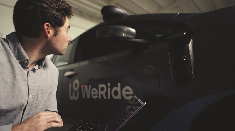
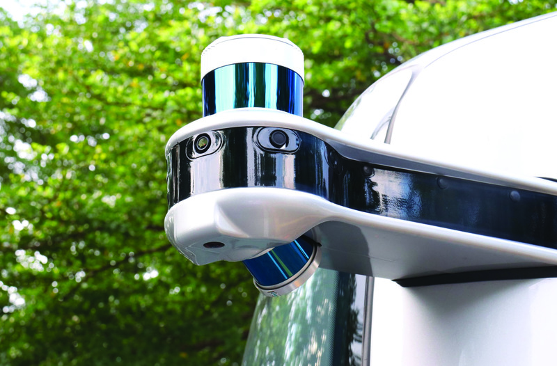
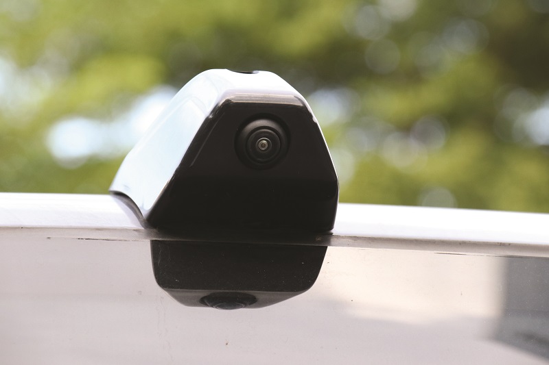
The vehicle’s anatomy is at first glance defined by its sensor architecture. Each outer corner features a structural arm extending outwards by roughly 30 cm, with a HD camera integrated at the end of each arm, and a Lidar for covering blind spots at the end of two of the arms. The two forward arms integrate one 64-channel ‘main’ Lidar on each.
Additional cameras and ultrasonic sensors are installed at intervals around the body for 360° awareness, obstacle detection and collision avoidance.
A GNSS antenna for high-precision localisation sits on the roof, while a millimetre-wave radar is installed at the front bumper. The main compute unit (MU) for self-driving computations is located in the front of the passenger cabin for easy access by technicians and engineers, and a power-control module is installed low in the chassis for proximity with the motor and inverter, as are control modules for the braking and steering systems.
The infotainment display and interface sits in the cabin ceiling towards the front, with an additional television screen at the front showing route progress and information to the passengers.
A single, central-drive electric motor at the bottom of the chassis handles Robobus’ traction and regenerative braking, while two distinctly smaller e-motors provide dual-redundant steering.
“The battery pack and BMS integrated at the rear of the cabin, rather than in the floor, allow us to have a very low floor and ride height,” Liu adds. “That’s important to making it safe and easy for passengers to get on and off the vehicle, especially elders, children and those with special mobility needs.
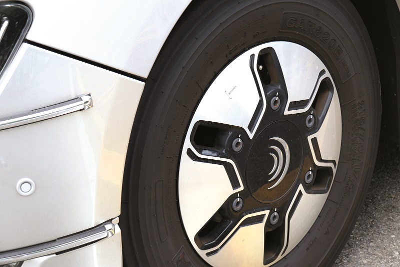
“We also avoided putting it in the roof, as some bus designers do, as that might have lowered the minibus’ roof height and presented another kind of safety or discomfort issue at head level. But maybe even more important was Yutong’s design of a double-wishbone suspension system for minimising the vibrations getting through to passengers, and so maximising their comfort when riding Robobus. It’s also proven great for slowing tyre wear, and hence reducing waste and usage costs over the vehicle’s lifecycle.”
Satellite and laser
Robobus’ localisation comes from a combination of GNSS for satellite position readings, an inertial sensor to enhance position accuracy with odometry and heading data, and Lidar perception to cross-validate position estimates via 3D modelling and recognition of landmarks in the surroundings. Although WeRide used solely GNSS data at first, the need to traverse the tunnel linking its island facilities with the Guangzhou mainland rapidly made use of non-GNSS-reliant navigation systems imperative.
To ensure these estimates come in consistently, a second MEMS IMU is installed onboard; this measure also enabling redundancy in inertial data.
“[The 3D modelling data] is stored onboard each Robobus, not on a cloud where connectivity issues might cause problems, but given the short, confined routes that Robobus traverses, the size of the data isn’t too much,” Liu notes.
Optimising the algorithmic aspects posed the biggest hurdle in Robobus’ localisation, given WeRide’s ambition to achieve L4 in safe autonomous driving, and required resolving issues such as localising when surrounded by other vehicles (by programming the software to use even minimal glimpses of recognisable landmarks to triangulate position).
“Also, the MU must arbitrate for when GNSS gives you one position and the Lidar gives you another; to resolve this, an algorithm assigns an evaluation score to every position estimate, which assigns an accuracy value to the readings from the different sensors based on the presence of obstacles or problems, which could make either the GNSS or the Lidar model inaccurate,” Liu says.
“But if both GNSS and Lidar model readings really aren’t scored high enough to be trustworthy then the system will use visual camera information to check for signs specific to the local area; for instance, road lane markers.
“So, even if Robobus can’t tell quite where it is in the world, at the very least it can ensure it is travelling safely on whatever road it is on. It can hence keep moving forwards at a safe pace, within the confines of its surrounding traffic, until one or both of the GNSS and Lidar localisation feeds are giving data with high confidence scores.”
Sensor complement
WeRide has consistently used Lidars as an important part of its sensor suites. The Robobus initially adopted main perception Lidar units in the front, and blind-spot Lidar units at the front left and rear right.
“And between version two and 2+ of Robobus, we moved to a 128-channel model for the main perception Lidar,” Liu adds.
Both the main perception Lidar and the blind-spot Lidar are 360° horizontal FoV systems, with the latter having a 104° vertical FoV (to the former’s 40°) for prudent blind-spot coverage. The main Lidar additionally functions with an operating range of 200 m (with 10% reflectivity), up to a maximum 230 m range, and generates up to 6,912,000 points per second in dual return mode, consuming 29 W in standard operations.
The 12 cameras around the body, meanwhile, are proprietary designs created at WeRide. One camera has a 30° FoV (vertical and horizontal), nine have a 100° FoV, and the remaining two are fisheye lens devices with 212° FoVs.
Why this diversity of onboard cameras? “Fisheye cameras are used to observe obstacles close to the vehicle,” Liu answers. “But then, the 30° FoV camera is a long-range device, primarily detecting traffic lights far away.”
Lastly, the 100° FoV cameras give a good combination of vision width and range for complete perception coverage of the minibus’ surroundings.
The radar at the front bumper is a 77 GHz unit, capable of distinguishing and classifying at least 120 different objects in typical operation, and of detecting objects up to 20 m away across a 60° horizontal FoV, or up to 70 m away with a 45° FoV, as well as up to 250 m when such objects are dead ahead.
“Admittedly, we don’t use the radar that much – if the forward cameras and Lidars should somehow both fail, then we fall back on the radar as a last resort,” Liu comments.
Perception model
WeRide’s sensor fusion algorithms perform both low-level fusions (where raw data is fused) and mid-level fusions (where the detections are fused). The main body of the algorithmic model fuses the cameras’ vision map to the Lidar point cloud, generating a unified output, which reconciles all raw data gathered.
“But L4 autonomy takes more than that, including the ability to define obscured objects that we can’t fully see, so our output models also feature image segmentation [AI recognition of multiple overlapping objects, such as cars in traffic], which heavily leverages the fusions of mid-level data,” Liu explains.
The perception model has a 40 ms standard latency, but is also capable of latencies as low as 10 ms, thanks to an emergency ‘shortcut pipeline’ in which the sudden appearance of a sizeable obstacle at very close range – particularly at a blind junction, a blind turn or when driving among cyclists where one might fall off their bike in front of the bus – will trigger a control signal to the powertrain (including brakes and steering).
That mode skips the detailed image segmentation or any other AI analytics, such as object classification, because in such instances alerting the Robobus that ‘something’ is ahead (and that safety actions are therefore imperative) takes priority over identifying and categorising what that something is.
The perception model also boasts an object contour error of less than 5 cm, which Liu attributes to not only switching from the 64-channel model to the 128-channel model as the main Lidar, but also to WeRide’s exhaustive commitment to ever-better data labelling.
WeRide’s engineers worked in Python to train the neural networks vital to achieving their models, and to construct their data processing and analytics flows. C++ and CUDA were used for the onboard deployment and offboard acceleration of the algorithms.
“We continuously used our C++-based ‘data swarm’ platform to simulate perception results – and analyse how they changed – with different versions of the algorithm,” Liu recounts.
“For the AI software, we used PyTorch, TensorFlow, TensorRT – all standard tools used across the industry, we’re fairly confident. And our cloud-based IDE [integrated development environment] and analytics system, hosted on our own internet data centre, was key to the engineers’ debugging work.”
The WeRide analytics interface combines a left window composed of six camera FoVs (three forward-facing, three rearward) with a right window showing a top-down, 2D, map-like view of the Robobus (represented by a blue polygon that Liu and his colleagues call the “ego”, always at the centre) within its perceived surroundings, to play comprehensive recordings of sensor-fused data across the two, all synchronised for timing and position data.
“The data collected by the sensors of the vehicles will be desensitised automatically by removing all personal information, such as the licence plate number or human face of traffic participants outside the vehicles accidently captured by the cameras, through an onboard masking programme,” Liu explains.
“After desensitisation, the safety driver selects the best durations of the desensitised data and uploads them to the cloud, where the IDE pipeline processes it into our analytics database for playback and analysis to train our models.”
“The top-down localisation view displays obstacles around Robobus as rectangular polygons per their bounding boxes, along with parameters like velocity, acceleration and jerk [the rate of change in vehicle acceleration over time, expressed mathematically as the first-time derivative of acceleration].”
The IDE window can be switched into from analytics to show a far more detail-heavy view for low-level debugging. Engineers can toggle between telemetry flows from virtually every subsystem at multiple fractions per second in each recording to isolate potential sources of incidents, errors or low confidence indicated by the self-driving algorithm.
They can also edit portions of the onboard algorithms and then generate simulations (starting at a user-specified timestamp of their selected recording of fused sensor data) of how the scenario might have evolved differently with a potential fix in mind. The simulation is output as a file that can be played by multiple engineers from the cloud for team input towards optimising each part of every autonomy-critical algorithm.
Prediction model
Also generated within an onboard prediction model are a large number of possible trajectories based on predictions of how traffic and other objects around the Robobus-ego will move. From those, a ‘selector’ module within the prediction model algorithm shortlists 12 trajectories as the most promising and then chooses whichever one manages the highest evaluation score as the final output trajectory for the powertrain to execute.
That score is based on anticipated safety, efficiency and comfort; the third parameter being a function of the acceleration, jerk, and whether there are very elderly or disabled passengers onboard meriting extra-careful manoeuvres.
“You’ll notice we generate evaluation scores for both positioning and trajectory estimates; the former are generated by the AI-trained perception model itself, while the latter are produced by our rules-based selector module. Hence, we feel we’ve combined the best of both technologies to work together, and ensure Robobus’ final trajectories are safe enough from both intelligence- and rules-based perspectives,” Liu says.
Safety response to sensor failure modes (including detected sensor misalignments due to vibrations or a leaf sticking over a sensor) typically consist of Robobus switching to a redundant sensor, reducing speed and increasing the distance maintained with the vehicle ahead.
The remote monitoring technician is alerted of the issue, and if a problem is severe, Robobus automatically pulls over to a safe location (using trajectories from the prediction model), or it can even stop in line if pulling over is dangerous and space for evacuation is possible.
If a battery malfunction occurs, standard procedure is to use some remaining energy to park in a safe place, while the remote monitoring centre triggers an alert and an apology to passengers to leave once the Robobus is parked, and await a second vehicle to collect them and continue their journey (as normally happens when crewed buses break down).
The first iterations of the trajectory prediction model were based largely on velocity data, and over time they also factored in vehicle dynamics, but WeRide gradually decided it still wasn’t accurate enough.
“We realised one day that what we really needed were the intentions of other vehicles – do they want to bypass us, cut in or just follow the road?” Liu recounts.
“That was when we introduced machine learning into our prediction model: to learn, based on preceding movements, what each vehicle’s driver was intending. Maybe six months later, we found we could very consistently predict high-level intentions, but what about the low-level – meaning is that vehicle to your forward-right going to try and cut in harshly or just gently?
“If it’s the former, we need to brake much harder and earlier than for a gentle cut. And we can’t just hard-brake every time to cover both kinds of cut-in, because sooner or later that will either injure our passengers or cause collisions with the vehicles behind us.”
Hence, based on map location and vehicle positions, the prediction model also calculates 12 possible trajectories (including velocities) of moving obstacles around the ego, each with an assigned score (aggregating its probability, as well as accounting for how dangerous its consequences could be). Naturally, each trajectory’s score updates to become a more accurate reflection of reality as more real-world traffic data is digested by the cloud IDE.
“Training the prediction model took millions of hours of well-distributed driving data, both from our uncrewed and driven vehicles, and we constructed a neural network with a transformer-type architecture, and designed multidimensional optimised objectives so that the models could come to reasonable decisions in all space distributions,” Liu says.
“Neural networks are interesting, but we’re convinced that data itself is the more important part of machine learning. Cleaner, better-distributed data is much more helpful to an intelligent model than having the best kind of neural network, and more and more neural networks used today are open-source, transparent solutions that anyone can get hold of. Your data is really what sets you apart.”
Compute systems
The self-driving algorithms run on a centralised computer (the aforementioned MU), with dedicated lower-level computers managing the cabin systems, comms, battery, brakes, steering motors, drive motor and inverter.
The current MU design is referred to internally as HPC (high-performance computer) 2.0, and it was based on an x86 architecture with integrated CPUs and GPUs.
A backup computer to the MU also provides redundancy, taking over from the MU to run the autonomy algorithms during failure modes, most often to drive the vehicle to a safe, nearby location.
For development ease, Linux and QNX are used as the operating systems. Above this, situated in the Robobus’ automotive software between the vehicle’s shared memory layer and functional nodes, is Mariana, WeRide’s proprietary middleware platform.
“At first, we used ROS, but there were a number of disadvantages that motivated us to develop our own middleware for smoother communications between the nodes and the shared memory,” Liu recounts.
“For one, L4 autonomous driving requires us to handle massive amounts of sensor data, so we needed higher inter-process communications performance than ROS could achieve. We also wanted a decentralised architecture, so that if one functional node in the automotive software stack fails it won’t affect another node; ROS has one root master, so if the master fails, everything fails.
“Mariana works without a master node: every node is functionally both a client and a master node, so there is no single point of failure and we’ve designed a lock-free structure into Mariana.”
As a final point, controlling the middleware allows WeRide to better control the quality and hence consistency of data, which has been indispensable for accurately replaying (and hence analysing) batches of sensor data and subsystem telemetry in sequence. This helps improve both the self-driving algorithm, the internal networks and the company’s simulation systems.
Across the network, a dual-redundant SAE J1939 CAN bus is used for comms between the MU and motor controller, while auto-grade gigabit Ethernet is used for the Lidars and cameras.
“Ensuring an optimal network architecture took a lot of early planning, especially for the different levels and sections of the network, and for each of the specific kinds of channels each part would need to use – as well as rigorous and exhaustive tests for validation, obviously,” Liu says.
“Signal integrity analysis tools were vital for seeing that signals were holding together well, and tools like Wireshark were really important for measuring the latency between different parts. Bandwidth management and signal prioritisation were largely handled manually, with just commonsense things like assigning vehicle-control signals a higher priority than sensor data being key there – if you’ve already detected a pedestrian on the road ahead of you, we need the vehicle to stop first and sense afterwards.”
Motor matters
The central drive motor is a permanent magnet AC machine, chosen for fine speed regulation, as well as the low weight and high power density of such systems. It runs on a 400 V bus; 800 V being excessive for the range and speed requirements of Robobus’s transport routes. Its peak power output is 120 kW, and such is its regenerative efficiency that WeRide estimates around a 21% range increase over the base, energy-derived range estimate.
In addition to regenerative braking, the brake-by-wire primarily functions using a conventional (by modern standards) combination of integrated brake control, electronic stability control and electronic parking brake systems, meaning a triple-redundant braking system, or quadruple-redundant if one counts the e-motor.
Both steering motors are also permanent magnet machines, although each one features a dual winding stator configuration for extra redundancy and hence safety.
The dual CAN bus extending to the motor-control systems from the MU principally monitors motor performance data (both in the traction and steering motors), braking performance and wheel-speed sensors. This data is processed via WeRide’s onboard analytics in real time to gauge whether control outputs are being executed correctly.
The powertrain is capable of centimetre-accurate control, which Liu says has been achieved by repeated trialling to identify when and where errors originate during operation (such as localisation, perception and so on).
“For example, to prevent errors coming from the inertia and movements of the vehicle, we first need to establish a very accurate vehicle dynamics model to fully understand the Robobus’ behaviours in different working conditions, and hence ensure that Robobus’ control strategy is actually in line with its physical characteristics and the effects that driving commands will have on how it’s moving,” he explains.
“Then, we use controlled testing cases to tune the algorithms for the best results during normal driving scenarios. Optimising localisation for fine motor control just depends on having an accurate, closed-loop feed of sensor data on what’s around Robobus at any given time. The aforementioned sub-5 cm object contour error helps in that regard.”
Energy levels
The battery pack integrates cells based on LiFePO4 cathode chemistries for the voltage and thermal stability (hence safety, particularly for passenger-carrying applications) that these are espoused for.
The pack outputs power over a 400 V bus, electrically matching the e-motor and its inverter, and it carries up to 173 Ah of energy, making for approximately 69.2 kWh. Its BMS hardware and software – including charging control software – are also developed and supplied by CATL, with battery management largely isolated from the MU to avoid burdening the latter with unnecessary monitoring and analytics.
The one battery parameter continually monitored by the MU is state of charge, so the Robobus knows when it is running low enough on energy to merit a recharge (though route planning and analysis should prevent this happening before the end of a working day).
“And, of course, if some health or performance parameter should shift far out of line, the BMS transmits an error code to the MU, and depending on the severity of the error and the location of Robobus, the vehicle will respond by stopping or pulling over to a safe location for passengers to disembark,” Liu adds.
Cabin systems
The design of each subsystem in the cabin, including lighting, air conditioning and door control, was allocated to different specialists among WeRide’s team. Each subsystem was then planned and drawn out individually, with the air conditioning developed through blueprinting of the system of air vents and fans, calculations of power requirements, and selections and placements of the compressors, noise-control parts, radiators, temperature and humidity sensors, and other components.
In the case of the infotainment screen, a 21 in (53.34 cm) LCD interface was chosen and integrated towards the front portion of the cabin’s ceiling. Safety systems chosen inside the cabin also include seatbelt sensors (with alerts triggered when passengers have not fastened theirs) and cameras monitoring the interior for incidents; for instance, altercations, medical alerts such as passenger heart attacks, or personal belongings being forgotten.
Each specialist was responsible for developing the software needed for running their portion of the cabin, including algorithms for controlling the air conditioning, the infotainment functions and the doors. The latter of these runs on the MU, intertwined with the self-driving algorithm, to ensure the doors automatically open and close only at specified destinations, and only when the vehicle has stopped. Buttons are also installed and connected with the MU for either pedestrians or passengers to activate the doors themselves at stops.
“Then, according to each cabin specialist’s planning documents, a verification stage followed in which the various cabin subsystems were integrated together into the vehicle design and simulated to gauge how well they worked together,” Liu says.
“That, followed by vehicle prototype tests, ensured there weren’t emergent issues, like EMI buildups between subsystems, uncomfortable noise levels for passengers, or resonances affecting the reliability of mechanical components like compressors or door motors.
“And, before either vehicle version left the factory for real-world trials and demonstrations, the project team conducted a joint review of every subsystem and function to verify if each one was acceptable from the point of view of pedestrians, passengers, fleet managers and engineers. If everything passes from all those perspectives, the product can go to market.”
Vehicle connectivity
A dual-redundant 4G radio system is installed on Robobus for consistent, uninterrupted remote safety monitoring, as well as teleoperation, if needed.
To enhance the consistency of communications, WeRide has developed its own multipass UDP solution, which enables multiple telecoms providers to be used, with the 4G system continuously monitoring and selecting whichever carrier seems to provide the strongest, highest-bandwidth connection at a given moment or place.
“Whichever provides the best result in the latest connectivity speed and latency tests, we switch our video and telemetry streaming over to that SIM card, and the technician at the remote station continues receiving the Robobus’ desensitised data that way,” Liu says.
Cyber security has also been a key area of focus, given the network connections accessible from the outside of the vehicle. The first piece of protection developed against hostile access or seizure of Robobus’ systems is a robust set of ID verification subroutines, by which the vehicle computer automatically checks the ID of any received command signal and rejects it if the ID is not a pre-authorised one.
“Secondly, we use a RSA [Rivest-Shamir-Adleman] algorithm to encrypt all data in our transmissions, and the third thing is vehicle-side command filtering: if the vehicle receives an unregistered command, the filtering process ensures it gets ignored,” Liu explains.
“Finally, the most important thing in our view for an autonomous vehicle: when Robobus receives a command, it has the autonomy to decide whether to follow the command or not, based on the safety measurements it’s making onboard.
“If someone tells the vehicle to pull over or change lane, or brake hard from high speed, the vehicle will analyse the safety of the scenario, according to its sensors and computers, and judge whether it would execute the command normally or not. So it’s virtually impossible for Robobus to be remotely forced into causing a traffic collision.”
The future
As accomplished as it is, the company is nonetheless hard at work in several areas relating to and even beyond self-driving transportation. For one, having demonstrated and validated Robobus units across numerous Asian cities, and one European one, WeRide is now developing a distinctly European version of the minibus, with a design slightly tailored in multiple places to fit EU homologation standards.
“We are also working closely with Bosch, combining our self-driving expertise with their vast automotive knowledge to develop L2 and L3 ADAS solutions that can be exported to OEMs worldwide,” Liu adds.
Closer to home, WeRide aims to launch its next-generation Robotaxi by mid-October, having quickly achieved commercial availability of its 1 t RoboSweeper autonomous street sweeper, which was released this April.
It is also proceeding in collaboration with the Nanchang-headquartered OEM Jiangling Motors on completion and commercialisation of the RoboVan, set to become the world’s first L4-level, autonomous cargo van designed for intra-city package delivery.
With all these vehicles set to bring intelligent autonomy across countless streets and highways, WeRide can doubtlessly be expected to become a globally recognised name in headlines, alongside the automotive giants of our world today.
Key specifications
- WeRide Robobus
- L4 autonomous
- Battery-electric
- Central drive motor
- Double wishbone suspension
- 10 seats maximum
- Dimensions: 5500 x 2050 x 2650 mm
- Kerb weight: 4.3 t
- Ground clearance: 260 mm
- Peak motor power: 120 kW
- Cruise motor power: 47 kW
- Battery capacity: 173 Ah
- Maximum operating speed: 40 kph (while autonomous)
- Operating range: 120 km
- Turning radius: 6 m
UPCOMING EVENTS


