


Wave J-1
One company is designing pulsejet engines with UAVs in mind, as Rory Jackson reports
Pulsejet engines are, mechanically speaking, among the simplest combustion engines in existence. They typically consist of a short, stubby intake pipe, a longer exhaust pipe, a combustion chamber, an ECU, and some fuel valving and injection parts possibly present in modern versions.
At a high level, such engines do not function dissimilarly to Brayton-cycle models such as the gas turbines previously covered in this publication: air is drawn into the combustion chamber, where it is compressed and mixed with fuel, and the resulting fuel/air mixture is ignited, triggering a combustion event that generates pressure and temperature, which is used to create thrust and exhaust.
The main difference is that the process in a pulsejet is unsteady and time-variant, and the compression for the fuel/air charge is provided by the acoustic waves from the previous combustion event, rather than by spinning turbomachinery, as in a gas turbine engine.

Additionally, the hot thrust/exhaust gas generated from a pulsejet’s combustion will shoot out of both the intake and exhaust tubes. Hence, referring to them as such may be considered a misnomer, except for the practical aspect of easy referencing.
However, rather than the air pressure in the combustion chamber simply dropping back to atmospheric level after combustion, the inertia of the exhausting gases causes them to overshoot, creating a vacuum effect.
This means that immediately after the exhaust phase, fresh air is sucked back into the chamber through both pulsejet tubes, enabling the combustion cycle to repeat (although most of the air subsequently burned will have come via the intake tube, given the shorter distance to travel than from the exhaust tube). All of this largely occurs as a consequence of air being a compressible medium with a spring-like nature – that quality also being the key to how humans vocalise.
“That combustion cycle can repeat indefinitely, its frequency depending on the size of the pulsejet engine; the bigger the engine, the lower the frequency, due to acoustic principles. Blow a large horn, you get a low-frequency blast of music; blow a small horn, you get something more high-pitched,” says Daanish Maqbool, CEO of Wave Engine Corporation.
“Most practical pulsejet engines operate around 50-250 Hz, so our J-1 engine product operates at around 100 Hz, regardless of where it is in its power curve, as a pulsejet’s combustion or operating frequency is dependent upon its geometry, not on how or when we throttle up or down.”
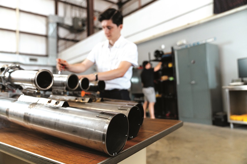
The J-1 engine is the first off the production line from Maryland-based Wave Engine, and it has been designed with UAVs in mind; specifically, UAVs with MTOWs of up to 200 lb (90.7 kg). In visual terms, the system presents exactly per the mechanical description above: two metal pipes, a combustion chamber, an ECU and some fuel-management parts (as well as a spark-ignition system).
In terms of performance, it produces thrust up to 53 lb of force (24 kg of force; 236 N) and has a thrust-specific fuel consumption (TSFC) of 54 g of fuel per kilonewton-second (g/kN.s), with an operating throttle range of 55-100% of maximum thrust. It weighs 7.5 kg and measures 163 x 32 x 14 cm. Extra specifications are either in the works or being finalised through benchtesting.
Jets, not detonations as part of understanding pulsejets, it is important to briefly distinguish them from pulse detonation engines. The latter have been discussed significantly across aerospace over the past decade, but operate based on a phenomenon termed ‘detonation’ in which the speed of the chemical reactions are equal to or faster than the speed of sound.
By contrast, a pulsejet such as the J-1 operates using ‘deflagrations’, meaning that its combustion reactions are slower than sound. Therefore, pulsejets are a simpler type of engine, particularly from a combustion perspective.
To understand the benefits of a pulsejet engine, it is best to compare it against a gas turbine, given that both produce thrust effectively using jets of hot air and are generally meant for high-speed flight, rather than the slower, longer-endurance flights of Otto-cycle engines such as reciprocating or rotary engines.
Gas turbines, whether for UAVs or crewed aircraft, are expensive devices composed of a small number of highly complex and costly metal parts; their expense coming not only at the point of purchase but also in running maintenance costs. These expenses rise when trying to develop gas turbines for smaller UAVs, as the components become more complex and expensive to manufacture the more they shrink, and the thermal efficiency (hence fuel efficiency) of gas turbines drops dramatically as the engine design gets smaller.

However, pulsejets are mechanically simpler than piston and Wankel engines, using very few parts, all of which are geometrically uncomplicated to manufacture en masse. This makes them relatively inexpensive to own and operate (albeit with a SFC still higher than that of reciprocating and rotary engines, although as suggested the use case is notably different for such engines).
“Historically, pulsejets achieved their greatest practical success during World War II, powering the German V1 flying bombs, because they were high-speed, cheap, and mass-producible power plants,” Maqbool recounts.
“The reason it didn’t achieve much success afterwards, especially in commercial applications, was because it used a mechanical valve to seal the combustion chamber’s pressure during ignitions, which wore out after maybe 45 minutes, and that was the lifespan of the engine. That ruled it out of pretty much all passenger aircraft, and a lot of defence aircraft too.”
Past pulsejets also suffered from undesirable fuel inefficiency. The V1 pulsejet engine (Argus As 014) had a TSFC of 3-4 pounds of fuel per force-pound-hour (lb/lbf-hr). Lastly, while not necessarily being high-vibration, it was an acoustically louder engine that was uncomfortable for any human sitting nearby.
“Today, however, we have a valveless engine design, which leverages modern innovations such that we don’t need mechanical air valves that wear out quickly, so that’s problem one fixed,” Maqbool says.
“My colleagues and I had long believed we could reduce fuel consumption by designing and optimising a pulsejet using modern engineering methods. We’ve gone as low as 1.8 lb/lbf-hr in TSFC, and we’re confident we can get it very close to 1 lb/lbf-hr, which is the realm of gas turbine engine TSFCs. Frankly, we’ve only just started on the TSFC optimisation phase of our r&d.”
As for being a loud engine, Maqbool points out that in some applications, noise is irrelevant. High-altitude, high-speed surveillance and urgent deliveries for defence users have often used less-than-quiet aircraft or other vehicles.
For applications that need to be quieter, including a range of commercial operations, some forms of noise damping are being developed. Among these, Wave has successfully integrated two of its pulsejets together, and acoustically coupled them to fire alternating pulses (such that when one is firing, the other is ingesting fresh air), finding that this arrangement cancels the other’s pressure pulses and therefore much of the noise emissions.
“We believe that all the technology components are there to create a power plant capable of making jet-speed aircraft without any moving parts – other than a couple of external fuel ancillaries – at a fraction of the manufacturing and maintenance costs of gas turbine jet engines,” Maqbool summarises.
Pulsejet thrust
For those confused by how the pulsejet draws in and expels gas from both of its tubes simultaneously, and wondering why it doesn’t simply stay in place, or stutter terribly in its efforts to produce forward thrust, it is important to understand that negative thrust is not created during the intake phase.
When air gets drawn into the two tubes, it does so as a sink flow, moving in from virtually all directions around the outside of their inlets. Sink flows do not generate any significant net momentum, given the concentric effect of the vacuum in the tubes, so no negative thrust is generated.
Then, when the burned fuel-air rushes out of the tubes at high pressure, it escapes as two jetstreams pointing in the same direction, creating a highly concentrated force that propels the aircraft forwards. The resulting jet thrust is unaffected by the intake phase’s sink thrust.
“This is a classical problem, however,” Maqbool says. “There is something called Feynman’s Sprinkler. Take a garden sprinkler that spins when spraying water and immerse it in a pool of water. Now run it in reverse so it sucks water instead; would it spin in the opposite direction?
“That might sound incredibly simple to resolve, but it has actually posed a serious, non-trivial physics problem. There are still papers coming out about it, and it relates to the conundrum of sink thrust versus jet thrust. Fortunately, we’ve been developing and testing this engine for some time, and we have concluded from our results that there is no negative thrust during the intake phase.”

Developing the J-1
The concept behind what eventually became the J-1 started in laboratory research at the University of Maryland; first theoretical work, then practical work, all aimed at better understanding how pulsejets operate, down to their most granular chemistry and physics.
“Those were small testbed engines, maybe 1.5 ft in length or so, and propane-fuelled initially. We gradually stepped up to experimenting with bigger engines, maybe a few feet long, and still propane-fuelled, but still scientific study articles, rather than being platforms meant for optimising performance,” Maqbool recounts.
“Those shed a lot of light on how pulsejets worked and how they might be engineered towards different ends. Then, somewhere around 2016-17, we decided to cross the valley into a full-scale pulsejet device to see if we could make something that would generate meaningful, real-world relevant quantities of thrust.”
In 2015, Wave Engine had already formed and been incorporated, although its real activities (as a company spun out of the University of Maryland) started after some point in 2017. To form blueprints for prototyping such a system, the company at Maryland first canvassed virtually every prior pulsejet engine design and item of literature to review and extract what made the most sense.
Rounds of continuous, iterative optimisation followed, with hefty reviews over points of geometry, dimensions and physics. In a major step forwards, using their basic understanding of the fluid dynamics, combustion, acoustics and other processes happening inside the engine (Maqbool having published two scientific papers on the matter), and the fundamental theory that all that entailed, Maqbool and his team were able to develop some computer numerical modelling software from the ground up. That software helped shed critical light on how the engine ought to be shaped, and how changing input or output factors would influence the design requirements.
“But, as with all practical projects, you can get incredibly helpful theoretical answers out of simulation software, but it’s never going to be perfect, because you eventually have to turn your prototype device on and start seeing what the simulation didn’t account for,” Maqbool says.
“The J-1 today has genuinely come from equal parts literature review, theory-based simulation work and experimenting with physical prototypes.”
In addition to the shortcomings of the Argus As 014, which kept it from gaining popularity in crewed aircraft after the end of World War II (and other nations’ pulsejets of the era were held back for similar reasons), Maqbool and his colleagues identified two more critical engineering targets necessary for modernising pulsejets for the requirement of UAVs this year, which occupied much of the past seven to eight years of development.
“One was optimising the engine design to start and operate on liquid fuel, because despite the inherent multi-fuel nature of pulsejets, most past designs were started or sometimes even operated entirely on propane,” Maqbool explains. “For a practical aerospace application, running entirely on liquid fuel was critical to producing a respectable amount of power. That was one of the first things we aimed for when we started making a full-scale engine after 2017.”
As a result, the J-1’s combustion cycle has been engineered for running on gasoline as standard, although the E85 ethanol-gasoline blend is also compatible with it, and Jet-A or JP-8 configurations are also possible.
Additionally, the team worked to establish digital control over the engine via an ECU, with EFI, to ensure that either a crewed aircraft’s fly-by-wire system or a UAV’s autopilot would be able to start, restart and throttle the engine without issue; these subsystems will be discussed henceforth.
Today, units of the J-1 have been delivered for trials with prospective customers and the design is in low-rate production, with plans to expand.
“It has been a constant process of mostly minor optimisations, bit by bit, and also working on the practical aspects of turning this into a product that people will actually trust and buy for their UAVs. Those have taken the longest; for example, optimising the efficiency in TSFC terms, or improving the reliability of the engine and getting the starting to function robustly and consistently,” Maqbool says.
“That last one isn’t trivial either. If you search for pulsejets on YouTube, you see all kinds of weird, convoluted, blower-type systems, so it’s honestly something a lot of technical people struggle with. But you can also see how our starting works, and that it works completely remotely, and only takes a couple of seconds. It’s a very predictable process.”
Intake
The J-1 is started using a small quantity of electronically controlled, compressed air.
“While some gas turbine engines can be started with some sort of electric motor, as reciprocating and rotary engines are, a lot of jet engines actually need compressed air to start, and most often it actually takes quite a lot of air to bring the engine up to operating speed. You can see on YouTube or on some passenger jets just how long it takes,” Maqbool explains.
“That also creates a problem for gas turbines in achieving mid-air restarts, because it’s a lengthy process and they can rarely carry a large enough air source to just deliver all the air they need for that. Ours can restart in just a few seconds using a small, onboard air tank, multiple times per flight if needed.”
The inlet of either pipe remains constantly open and unobstructed without the need for a throttle to regulate air intake (their exact diameters must remain undisclosed as a key part of the engine’s geometric optimisations).
As mentioned, EFI is used for fuel delivery, being a core aspect of modern tech that Wave Engine has brought into the pulsejet realm (the engine can be fuelled without EFI, but this would not yield as fine a degree of control over its operation).
“We’ve worked with several ECUs to see how well the results were in terms of fuel and power management, and we customised a range of proprietary ECUs at different levels of simplicity or complexity. The custom design we’ve selected to go into production of the J-1 with is one of the simpler ones, genuinely for the sake of simplicity and reliability,” Maqbool explains.

“A more complex ECU and EFI system would be a definite way to get more fuel efficiency, but, at the same time, because this is going to be a new sort of engine for a lot of people, we need to prioritise getting the reliability and ease of integration right.
“We do plan on moving to more sophisticated engine management and fuel injection approaches in our future generations though once we’ve established the engine technology among UAV integrators.”
While Wave Engine has tried to draw upon standard COTS components where possible, the fuel injectors, fuel lines and associated wiring have been slightly modified into a form factor more suitable for this engine.
Fuel/air mixing in the J-1 happens slightly differently than in gas turbine mixing chambers. While gas turbines mix the air and fuel with a steady flow of both, in pulsejets the air moves with an inherently unsteady flow; that is, with a pressure wave almost constantly springing back and forth.
“That motion does help with the mixing a bit, but unlike a steady flow environment – like in gas turbines, where you have a lot of time to mix and time to burn – our engine comes with a very limited time to burn,” Maqbool says.
“Our engine runs at 100 Hz – that’s the equivalent of a four-stroke engine running at 12,000 rpm in combustion speed terms. It brings some challenges in the physics of it all, and in how tightly one has to electronically control the injection timing and pressure, but the highly turbulent environment in the combustion chamber helps us pull off a quick and thorough mixing.”
Further gains will be achieved through CFD optimisation of the combustion chamber in future versions of the engine. Productionising the J-1 has been prioritised over ‘completing’ CFD simulations for now, as performing CFD work on pulsejets is inherently complicated due to the challenges of modelling the properties of the airflow inside the engine.
“The airflow in pulsejets’ innards is unsteady, compressible, multiphase and reactive – that’s every type of quality that can make CFD complicated. There is literally no way left to make our CFD more difficult,” Maqbool says. “That said, it makes absolute sense to open up CFD investigations more and more, and we do want to engage heavily in that in the future. We just haven’t prioritised it, so as to avoid splitting focus away from core functions, reliability and controllability.”
Squish and burn
The pressure waves of air coming from either pipe contributes some compression to the fuel/air mixture in the combustion chamber. If one placed a pressure sensor inside, one would see a spike in pressure during and immediately after the combustion event, and before intake one would read negative pressure.
“Some have assumed a Lenoir cycle for pulsejets in which there is no compression, just a constant volume combustion event where pressure spikes and then gradually comes down, and that’s it, never any negative pressure in the chamber,” Maqbool says.
“Frankly, I don’t agree with that: there is exhaustive evidence indicating that a compression wave comes back during intake. It’s not huge, and the two columns of air ramming into each other aren’t quite a full-on mechanical piston and cylinder head, but it does provide some squish, which assists with the combustion.”

A modified COTS capacitive discharge ignition system is used to spark the fuel/air mixture, although a customised and proprietary system is being developed for embodiments where heavy fuel is preferred.
With the air inlets being open and valveless, the engine is throttled up and down by regulating the fuel flow up and down via the EFI.
Maqbool reports that unlike most gas turbines, which can take 5-15 seconds to go from idle to maximum rpm due to the mass and inertia of the rotating machinery, the J-1’s throttle response is extremely rapid.
“Our only inertia to overcome is the mass of the gases themselves, which isn’t a lot, so throttle changes can execute really quickly, as needed,” he says, adding that changes from idle to maximum thrust can be achieved in under a second.
More challenging is thermal management. The J-1 has been designed as an air-cooled engine (continuing the theme of simplicity), and the system will run extremely hot if forced to operate stationary in a braked UAV on a runway for too long.
“For any UAV subsystems installed right next to the engine, we recommend using a little bit of reflective tape or similar heat shielding, which has been demonstrated to work well with most common airframe materials, including fibreglass and carbon fibre. If the engine is embedded inside the fuselage, the design must include prudent inlets and baffling for cooling airflow, as you would with many engine designs,” Maqbool says.
“Granted, our demo videos show the J-1 mounted externally atop a model aircraft as a testbed, but that’s just because we wanted a really simple demonstrator. It could absolutely function completely normally in an embedded, internal integration or a rear-mounted configuration, so long as the design takes air cooling into account.”
Additionally, as the J-1’s exhaust phase produces pulsations that radiate outwards, it is worthwhile to allow the pipe outlets to protrude from the craft (as one typically would with exhaust pipes) to ensure the pulses do not impact or affect any wing-, tail-, or fuselage-mounted subsystems, particularly for survey applications.
ECU design
The ECU can be mounted roughly anywhere except on the engine (to avoid overheating), with a common approach being to install it on the firewall. As mentioned, the ECU design is custom and entirely proprietary to Wave Engine (although manufacturing is provided by a third-party production house), with simplicity at the forefront of its development priorities.
“The intent was for the ECU to handle all fuel supply, ignition and control functions over the engine as an integrated package handling all its inputs and outputs, with no significant ECU programming work left to the end-user, and a single wire harness linking it out to the flight controller,” Maqbool says.
“On the fuel side, we supply the pump, filters and injectors – not just for ensuring a turnkey package with our ECU, but also because a lot of our technical IP revolves around specific selections of those items, with some pumps, for instance, working better than others.”
Fuel is currently delivered using an electric pump powered by an integrated battery controlled by the ECU (for direct control and to prevent users having to power the pump themselves). Key selection criteria included the pump being able to hit the target fuel pressure and flow rates, and also that it could operate on minimal current draw to ensure the battery could be kept as small as possible.
“We found most pumps on the market are actually overpowered for our application, so ours is on the smaller end of the COTS systems available,” Maqbool says.
Control of the pump, injector and ignition is handled via pulse width modulation (PWM), both for its use in developmental fine-tuning and its ease in connecting with the full range of flight controllers (including non-CAN ones).
Going forwards, Wave Engine plans to offer other forms of interfacing on customer request (and Maqbool reports they have built ECUs that communicate by CAN in-house), particularly to make detailed performance and health data available to end-users for diagnostics and maintenance tracking.

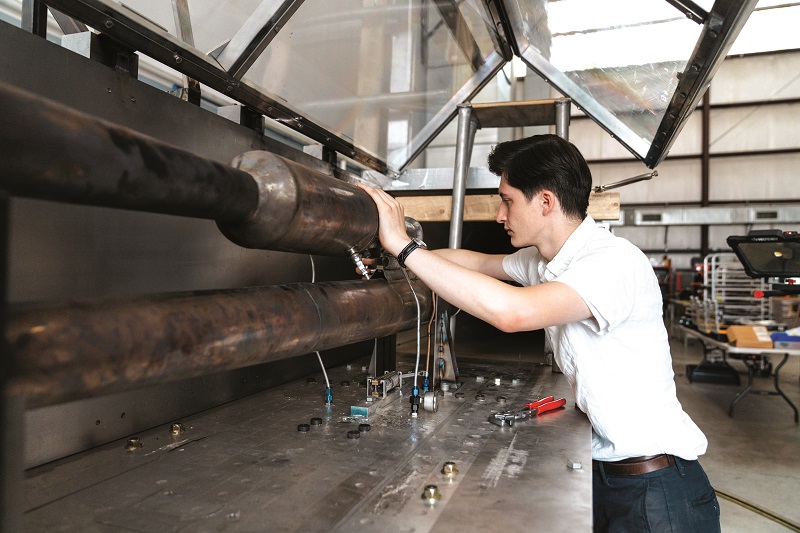
Metalwork
In pursuit of an inexpensive, rapidly producible engine, the three metal components of the J-1 have been predominantly made from 304 stainless steel, being the most commonly found steel and easy to work with.
“There’s aluminium in a few key places where weight-saving has been prioritised over strength, but there are workshops all over the place that can do metal-forming and -bending with 304 stainless, which means we have easy access to production suppliers, depending on our need,” Maqbool says.

“We also have CNC-milled parts in a few places, but ultimately we want to reduce those because it’s just cheaper to stamp or bend metal.”
Using more advanced materials such as titanium alloys could halve the J-1’s weight, although this would at least double the material and manufacturing costs. It would additionally go against Wave Engine’s targeted advantages in cost, manufacturability and simplicity, however, so it is not a priority for now.
Once formed to shape, the two pipes and the combustion chamber are welded together to create a single, solid piece of metal. Mounting brackets and other peripherals may be bolted on afterwards. As of writing, no liners are being used inside the engine, although Wave has built several engines with liners, and anticipates applying coatings or other internal materials for special applications with specific thermal, noise, packaging or longevity requirements.
“Though in theory, liners could reduce the amount of heat the engine radiates outwards, which is significant, that could improve performance by reducing thermal losses,” Maqbool notes. “In our experience, it won’t be a huge efficiency gain, but it won’t be a net boost of zero either, in theory.”
Future
With steady interest in the J-1 from UAV manufacturers, and optimisation plans for the engine laid out, Wave is now turning some attention and r&d resources to its larger sibling, the K-1, which produces 220 lb (99 kg) of thrust force.
“UAVs are always going to be an important market for us, and I do expect to see a lot more aircraft with the J-1 before we see them integrating the K-1,” Maqbool says.
“And, as important as defence markets have always been for pulsejets, there are commercial applications for pulsejet technology too, and we don’t want to lose sight of those, or what it will take to meet the standards those manufacturers and integrators have.”
Key specifications
- J-1
- Pulsejet
- Spark-ignited
- Air-cooled
- Gasoline (E85, Jet-A and JP-8 optional)
- Weight: 7.5 kg
- Maximum thrust: 236 N (24 kg of force)
- Thrust-specific fuel consumption: 54 g/kN.s
UPCOMING EVENTS


