


UAVE 120 cc four-stroke
(Images courtesy of UAVE except where stated otherwise)
To the extreme
Rory Jackson takes a deep dive into the DS120 and 15 years of optimisation
UAVE (pronounced ‘wave’) is a UAV manufacturer and operator that has been active for some time, during which it has accrued an eclectic range of missions and capabilities, flying many extreme environments and advanced payloads with its Prion UAVs.
At the centre of all its works has been the DS120, a four-stroke, single-cylinder, spark-ignited engine, unique to this UK-based company and its aircraft. While UAVE does not sell this engine (its business is focused on a range of surveying services and it has been granted BVLOS flight clearances in select locations), the DS120 recently grabbed our attention for having received over 15 years of optimisation, making it worth a considerable deep dive to understand the wealth of engineering techniques used and high-end components inside.
UAVE was founded in September 2013, following a management buyout from TGS-NOPEC (now TGS), a Norway-headquartered specialist in offshore oil and gas exploration, focused mainly on the North Sea and the Gulf of Mexico.
As ships for such work could cost $200,000 per day (at 30-60 days per mission), TGS-NOPEC had grown interested in UAVs for improving offshore survey precision and hence shortening such missions by potentially tens of days (and millions of dollars) per year.
Thus, in 2006, TGS-NOPEC acquired MagSurvey, a UK company that was focused on onshore mineral explorations with a small (2.8 m wingspan), fixed-wing UAV, with the intent of scaling up its tech to a large, fixed-wing UAV suited to long-endurance offshore flights. It injected r&d capital into MagSurvey and put Phillip Slater in charge of managing the project.
Today, Slater is managing director of UAVE, which relocated from Dorset to the Aberporth Technology Park in Wales in 2014, to be near its primary airfield and key suppliers. As he recounts: “Within MagSurvey’s supply chain was DGS Engineering, an engine company in Daventry, and part of the hotbed of engineering competence that grew around the huge Ford car production plant there.”

DGS Engineering was founded and led by David Short (now retired), who, in addition to supporting the production of large engines for Ford and other businesses, also produced small, efficient, lightweight engines as in-house r&d side projects. Among these was a single-cylinder gasoline engine, which was intended for diverse, ground-based applications, but Slater and his colleagues were drawn to its mechanical simplicity, low weight and material selections, seeing potential in it for aircraft propulsion.
“Efficiency was also critical, because we wanted to fly 1000 km per flight. That had already honed our selection of engines down to a single-cylinder four-stroke, known to be the most miserly type of engine at sipping fuel,” Slater muses.
“The efficiency requirement meant we couldn’t have a Wankel or two-stroke. It was either a single- or two-cylinder four-stroke, and anyone who knows motorcycle endurance rallying knows that a single cylinder is also an optimally low-rpm, high-torque, four-stroke engine.
“Anyone with an understanding of propeller design knows a propeller should have lower rather than higher rpm: the higher the prop rpm, the more each blade catches up with the airflow disturbed by the advance prop blade during rotation.
“And we didn’t want the added weight of a gearbox or liquid-cooling circuit, so we needed an air-cooled engine, with max 5000 rpm at its output shaft, and a preferential operating range of 3600-4000 rpm to match our concept propeller sizing.”
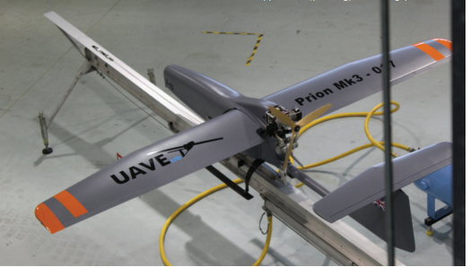
Slater and his team opted to develop Short’s engine for its new aircraft, which they named Prion Mk.3, after MagSurvey’s Prion Mk.2, which flew for the first time in July 2007 (in an airworthiness inspection flight for the UK CAA) after 1.5 years of development.
“Short had a lifetime of engineering experience and he fed that into the engine. Recognising that, we acquired the IP for it from him in 2013, when we did the management buyout – why it carries his initials as the DS120 to this day,” he says.
That buyout occurred after TGS-NOPEC chose to scale back its usage of UAVs, but not before the Norwegian parent company tasked the teams behind the Prion Mk.3 (and the DGS120) with an Arctic-based aeromagnetic mineral survey, successfully locating kimberlite pipes – the most important source of mined diamonds today – to attract potential buyers.
“But, with regulators having made it impossible to repeat such mineral surveys outside the Arctic and similarly remote locations, we engineers bought the company and began diversifying,” Slater recounts.
“However, we kept developing the engine on an unchanged track, because it had proven itself to be extremely capable, including incredibly consistent and reliable performance in long BVLOS flights lasting many hours. We’d also accrued a huge library of data from active flight exercises in the Arctic, and elsewhere, to inform future optimisations in areas like fuel efficiency and lightweighting.”
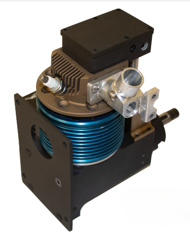
Today, the DS120 is a 120 cc air-cooled engine, weighing 4.6 kg and producing 8 hp at a 4600 rpm maximum continuous operating speed, with a redline speed of 5000 rpm. Naturally aspirated, it runs on RON90 petrol with 2.5% oil mix, although the company has previously developed a heavy fuel version and is open to doing so again. To date, it has operated up to 10,000 ft (3.04 km) AMSL and has a TBO of 1000 hours, with servicing intervals every 50 and 200 hours.
It typically sits upside down, with its cylinder at the bottom and the crankshaft running at the top, to keep propeller vibrations away from any payloads, and the steel crankshaft away from mining survey magnetometers to prevent ferromagnetic interference.
A camshaft sits near (and is gear-driven by) the crankshaft, and actuates the cylinder’s two conventional overhead poppet valves via a conventional valvetrain of pushrods and rockers, with coil return springs.
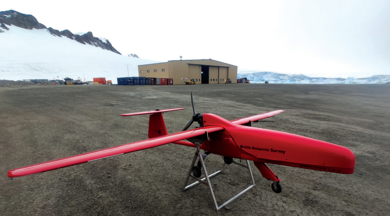
(Image courtesy of Will Clark & Carson McAfee, British Antarctic Survey)
Air cooling
Minimising weight means the DS120 does not have water jackets or an oil sump. Instead, the engine’s fuel contains a small amount of two-stroke oil, with the unburned oil vapour passing down the piston’s sides to lubricate the bearings; fins about the block dissipate heat.
Several parameters are also controlled via the ECU, such as cooling the engine internally by running the fuel slightly richer (if thermal efficiency should occasionally take precedence over fuel saving). To further moderate the engine’s temperature, UAVE developed a bolt-on heatsink, which affixes to the exhaust port, sitting in the airflow aside the engine bulkhead, to draw away and dissipate considerable heat from the cylinder head.
These techniques and other optimisations to the finning were first developed to suit a number of meteorological flight services performed in India, not long after the management buyout, as temperatures on the tarmac and in the engine bay were naturally far higher in India than they had been in Britain, and especially the Arctic.
“We also designed a big air scoop on the side of the aircraft, which feeds onto the airbox, so any air which doesn’t get drawn into the throttle body passes along the airbox and flows onto the cylinder head,” Slater adds.
“West Wales Airport was where we first reached 10,000 ft, with a very aggressive climb. We took that experience to India, where we achieved the same target altitude. The customer there was very demanding, wanting to continually load the aircraft with more and more payload weight.
“Eventually, there were 11 different instruments on the Prion, which meant a variety of complex integration challenges. We were also flying at our MTOW in hot, thin air – basically everything an aircraft hates for take-off conditions. But the project was successful, and it really helped us push our power plant further and harder than ever before.”
Control and operation
Also, after the buyout, the company sought to establish a testbed to cycle, measure and experiment with the UAV engine in a sophisticated manner, bringing in some new staff, including former racecar engineers to optimise its performance, efficiency and reliability against its weight and cost.
“They diversified the test suite, and started working with different kinds of injectors, CFD approaches and exhaust types in a highly controlled test environment. Based on their findings, we started designing our own fuel-delivery systems, and went with an ECU from GEMS to control fuel-injection quantities and timings more precisely than before,” Slater says.

“With our ecosystem of suppliers around Daventry and in Wales, we wanted to use an ECU from within the UK too, and GEMS have seen a lot of success in performance and rally cars. I also know of at least one other UAV in the UK that they supply ECUs to.”
UAVE worked closely with GEMS to produce and optimise new ECU code vital to the precise monitoring and timing of the DS120’s injectors, and it has since been redeployed in other applications with the company’s blessing.
To further optimise gas flow, the inlet and exhaust components are largely bespoke designs. The former is optimised to enable rapid, direct delivery of atomised fuel, from a single port injector running via the throttle body, onto the back of the inlet valve bell shape.
The exhaust manifold integrates an oxygen sensor for measuring O2 in burnt gases to determine whether the fuel mixture must be made leaner or richer (by the ECU shrinking or extending the injector’s pulse duration), depending on altitude. The engine is typically started using a handheld starter in front of the propeller, and a toothed crown on the crankshaft’s flywheel is used by the ECU for ignition timing.
“Most engines use a Hall sensor combined with a bit of magnetic material in their crankshafts to trigger the ECU for ignition timing, but you may remember that one of our primary applications was mineral detection. Well, carrying a magnetometer for mineral hunting means you can’t have any ferromagnetic materials anywhere near that payload, so we couldn’t use a Hall sensor,” Slater says.
“Instead, we do tooth counting. There’s 24 teeth on the crown, equally spaced, with one extra one inserted between, and an optical sensor counts the teeth and bases the spark timing on when it sees that extra one.
“The optical sensor works more than quickly enough to advance or slow the ignition timing however we’d like. At lower rpm, we might have it firing 6° or 7° before TDC, but by the time we reach 4000 rpm, we might be at 27° pre-TDC.”
Also connected to the ECU is a manifold absolute pressure (MAP) sensor to track engine load and inform injection cycle lengths. An air tube connecting the inlet manifold to the ECU enables the necessary measurement of the difference between ambient atmospheric pressure and how much air the engine throttle is demanding.
The throttle itself is an adapted COTS unit, positioned under the engine by the firewall, to match the high-prop pusher positioning of this engine at the top rear of the Prion Mk.3’s fuselage, and an injector housing installed on the side of the engine feeds into that.
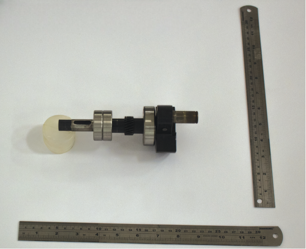
Crankshaft balancing
While the crankcase is conventionally designed and milled from a single piece of 6061 aluminium alloy, the crankshaft is unconventional in a few ways, not least for being supported at only one point.
“Most crankshafts have a bearing or two at each end to support and hold them in place, but we have three bearings at the middle and those act as a slight pivot point – something like the stationary mid-section of a seesaw – while the output shaft is free-floating,” Slater explains.
“On one end you have the reciprocating mass of the piston, con rod and so forth, along with the flywheel and the drive gear for the valve train; on the other you have the propeller. The result is that the stressed components of the powertrain perfectly balance each other out, and those three bearings sitting almost equidistant between them effectively manage the loads and stresses transmitted from them.”
Two of the bearings sit as a pair near the crank nose, while the other, larger bearing sits on the other side of the counterweight from the big-end bearing. The smaller pair of bearings and the larger one also sit equidistant from a gear, machined at roughly the middle of the crankshaft’s length, for driving the camshaft.

A critical part of optimising the DS120’s performance (culminating in 2021) was balancing the engine, particularly balancing the crankshaft, without having access to significant in-house crankshaft-balancing equipment. To do that, UAVE partnered AMB Engineering, a Sheffield-based specialist in crankshaft balancing; the process involving significant remote collaboration due to COVID restrictions at the time.
In-house, Slater and his team stripped down the engine, measuring and weighing each part of the reciprocating assembly, down to its circlips and piston ring.
“We then designed and built a jig to keep the crankshaft balanced, and learn what weight distribution was necessary to keep it ‘neutral’ and free from any inclination to rotate in an unbalanced fashion,” Slater says.
“We reported all our numbers and findings to AMB Engineering, and the core matter of their response was that we needed to put inserts of a special tungsten alloy into the crankshaft counterbalance, and they gave exact dimensions for the inserts we needed too.
“But we’d also made our own calculations, so we made two crankshafts for balance testing – one with their inserts and one with ours. Unsurprisingly, they were right and we were wrong.”
Three years later, UAVE continues to use the inserts that AMB specified, including the exact proportions of the alloy, Mallory metal. This highly dense and heavy tungsten alloy is developed and specialised for crankshaft counterbalance inserts, especially in single-cylinder engines, which can require compensation for the single reciprocating mass.
JS Engineering, a specialist engineering company located within one mile of UAVE, mills out a hole in the DS120’s crankshaft counterbalance, and inserts and finishes the Mallory metal insert with an interference fit, in a manner such that the engine’s vibration is heavily minimised.
“Vibration becomes especially critical when you’re trying to optimise your engine’s performance up to its very top echelons, and thanks to this whole shaft-balancing journey, we now have a phenomenally lower-vibration engine than the older version we flew in the Arctic and in India,” Slater says.
Aside from the Mallory metal inserts, the crankshaft is largely milled from a single piece of EN36 steel with a very light case-hardening of roughly 0.009 cm in thickness, including the shaft, counterbalance and the crank pin for the con-rod big end; the latter being press-fitted into a crank arm opposing the counterbalance (though not before the single-piece con rod is fitted onto the pin).
The crank-journal surfaces are ground to precision-fit the bearings and the entire shaft is then sent to a gear-cutting specialist, which cuts the helical teeth for driving the cam gear. The bearings are pre-greased, oil-sealed bearings, similar in geometric design, although the bearing closest to the combustion chamber has a steel seal (to withstand the heat it must endure), while the two nearer the propeller run much cooler and thus have plastic seals.
The con rod is of milled steel, with a needle roller bearing in its big end and a bushing in its small end. UAVE is looking to replace the big end bearing with a new, graphite-impregnated bronze bushing. Such bushings have been used previously in very high-rpm electric motors; rather than featuring an oiling hole, such a bushing would gradually release atomised graphite over its lifetime, lubricating effectively.
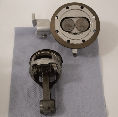
Piston
The DS120’s aluminium piston is supplied by Vision Spares (Trading as DIY Spare Parts). Early in the engine’s development, while frustrated with wear and overheating from DGS’s billet-cut pistons, Short provided Slater with a test engine unit fitted with a COTS piston he had found (for its “skinnier” piston rings and the prospect of reduced friction) and subsequently modified to optimise weight and other parameters.
The engine ran 10 C cooler to the pair’s delight, and so they gradually worked through Honda’s contacts until its kart-racing component company identified the part numbers for the piston, piston rings, gudgeon pin and circlips, sending samples to Slater to confirm.
“The great thing about using a Honda Racing-cast piston is that it’s already dimensioned to thermally expand and contract consistently within a perfectly cylindrical bore, so that it doesn’t seize or cause wear effects as a less sophisticated piston might when overexpanding on the exhaust side, compared with the cooler inlet side,” Slater says.
“We do mill out surplus material from the piston skirt to reduce weight, as Dave taught us, because we’d already done our weight-balancing calculations for the tungsten alloy inserts that go into the crankshaft, so we needed a like-for-like piston weight, including bearings, rings, gudgeon pin and so on.”
The piston features two rings – both for compression with no oil scraper, as UAVE wants oil to run past the piston, rather than keeping it in the combustion chamber (to date, no issues relating to blowby have had a measurable impact on any part of the engine).
The gudgeon pin is held in place by two bronze ‘top hat’ collars, as well as the bronze bushing, drilled oil path in the small end lubricates those components.

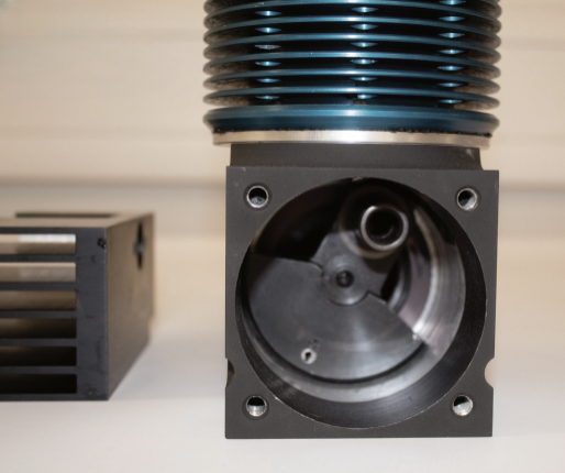
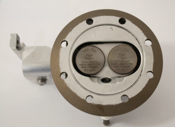
Cylinder in cylinder
The cylinder is composed of a steel liner, inserted into a shrunk-fit cooling jacket cut from aluminium (including cooling fins). The main body of the cylinder head is cut from aluminium and finned externally for cooling. Once cut, a smaller, cast-iron cylinder is inserted into the head and pinned in place.
This small cylinder serves multiple purposes. For one, it functions as a valve seat or floor for the valve springs to sit and compress against. It additionally serves as part of the rocker box housing, and an aperture is cut into part of it, which functions as the exhaust outlet.
“We are also experimenting with a bronze insert for that cast-iron component, which will form a valve guide, as added insurance against valve stems sticking. The bronze is a great material for mild steel to pass through. The valves themselves are excellent, and I’ll explain why later, but the bronze valve guide could prove really helpful for getting that final 1% of reliability into this engine,” Slater says.
The head clamps atop the aluminium cylinder cooling jacket via a squish ring made of steel, dimensioned and tuned to optimise the compression ratio for the DS120’s 3600 rpm cruising speed.
One-lobed camshaft
The valvetrain has been kept as mechanically simple as possible, while incorporating a number of high-end components, both of these qualities contributing to the engine’s lengthy TBO.
A single camshaft actuates two side-by-side, upright valves – one for the intake, one for the exhaust – via two conventional sequences of pushrods and rockers, as mentioned.
As previously indicated, the camshaft is driven by a crank gear, with each full rotation of the crankshaft rotating the camshaft by 180° per the Otto four-stroke cycle. The cam shaft and gear are made from ground, flat, stock steel (also known as ‘gauge’ or ‘tool’ steel), heat-hardened and precision-fitted together.
Unusually, the camshaft has only one lobe, rather than two. One cam follower rests on the lobe’s left side and another on its right, with their differing shapes and dimensions determining the sweep of the engine (the timing by which the inlet valve opens and closes, the piston compresses, and the exhaust valve opens and closes).
“Because of how we’ve differently shaped the inlet valve’s cam follower and that of the exhaust valve, as well as the corresponding shape of the cam lobe, each valve opens in a different way to the other,” Slater says.
Within each cam follower is a pushrod, running up to the cylinder head and interacting at their top ends with conventional tappets (integrated with rocker arms of EN32 case hardened, heat-treated steel), with a valve-clearance adjustment screw embedded in one end. A single spindle in the rocker box allows the valve tappet to rest in a simple collet arrangement atop its valve.
“Most valve collets nowadays involve a two-piece collet, which clamps around recesses in the end of the valve stem, and the valve spring typically holds that recess in an increasingly tight clamp. We have a simpler system than that,” Slater explains.
“We have a single disk, which presents over the valve, and the valve moves towards the centre of that disk, after which the valve-spring pressure keeps that located correctly. It’s a very simple approach, not overly sophisticated – put that in a Formula One engine, and you’d have problems with dislocation and valve bounce – but as we never go above 5200 rpm, it works great for us.”
Valve to survive
The valves are supplied by G&S Valves, which also makes valves for Formula One engines. “At first, as with many components in the engine, Dave made many of the components in-house, but as I worked on enhanced fuel mappings and approaches to getting oil from the cylinder into the crankcase, down to the valvetrain and into the rocker box, I started to get better performance out of the engine until a couple of valve stems snapped and fell into the cylinder during a test run,” Slater says.
“Fortuitously, I was soon introduced to G&S Valves, based in Guildford, which is a hotbed for Formula One technical expertise, and after hearing about my problem, they manufactured – at a reasonable cost – incredibly strong, customised valves, based on our specifications, so they’re a near-direct fit to our valve seats.”
The bodies of the valves are of 1.4882 steel with a pulsed plasma nitriding treatment. Chemically referred to as X50CrMnNiNbN21-9, this is an austenitic steel, specified for engine valves, containing chrome, manganese, nickel, niobium, nitrogen, phosphorus, silicon, sulphur and tungsten.
The valves are held closed using standard COTS valve springs, although UAVE experimented with high-compression springs before passing on them due to issues with pushrod bowing. The cylindrical component functioning as a valve seat is cast iron, and it is precision-machined and refaced with a diamond-cutting machine to fit closer to the dimensions of the G&S valve.
“A local technician has the diamond-cutting machine, as well as a scanning tool for measuring the geometry of the valve guide and to gauge how much excess movement or stiction might occur during thermal expansion. We’ve got aluminium, cast iron and steels working closely together at TDC, so it has paid to stay mindful of the differing coefficients of thermal expansion those all have,” Slater adds.
Electric power
While the engine is typically manually started, without a starter-alternator, an inline alternator is integrated and runs on the crankshaft. The alternator is a three-phase, 500 W system, supplied by Sullivan UV of Acutronic Power Systems, and the AC power it generates runs into a Sullivan power regulator. The resulting DC is regulated and distributed by the device into stabilised 5 V, 12 V and 24 V output buses to safely and efficiently power the subsystems across the Prion Mk.3.
“We’ve worked with Sullivan since 2006, back when they only made single-phase systems; of course, three-phase is far better,” Slater says.
“Using a starter-alternator is a nice idea, but, frankly, we’ve not had a commercial reason to do so, and I’m not sure I like the idea of putting such a heavy-duty device as a starter-alternator on a 120 cc single-cylinder engine.
“It could work on a twin-cylinder Boxer 60 cc unit, because the torque output and vibration would be smoothed out via the nature of the four-stroke. But kick-starting a large, 500 cc, single-cylinder, two-stroke motorcycle engine is quite hard; trying to use a pancake starter-alternator to start a 120 cc single-cylinder four-stroke is probably quite hard as well.”
Future
While the core technology of the DS120 is mature by now, UAVE is presently working on a slightly modified version that will function with a tractor propeller, with the end goal of making a dual-engine Prion Mk.3, running on both a tractor prop engine and a pusher prop engine.
“Customers want more and more payload capacity per flight, so that’s how we’ll go from carrying 20 kg of payload to 50 kg of payload,” Slater says.
“We’re in the process of adapting the cylinder-head design so we can swap our manifolds around and then just turn the engine to face its propeller forwards, with one or two other components inside the engine mirrored to optimise performance. Each propeller will counter-rotate relative to the other, which will enhance flight stability as an added benefit.”
Beyond that, UAVE is looking to expand the size of its company and potentially experiment with optimisations ideal for defence applications. These include finding ways to reduce steel content in the engine, being a strongly visible material on radar, as well as aluminium (the Prion Mk.3 or Dragon is otherwise mostly fibreglass, a radar transparent material, ideal for stealth-critical applications).
With its wealth of experience as backing, multiple hubs of engineering expertise supporting it and a tightly honed engine at its core, UAVE can be expected to continue flying its aircraft far and wide to new heights and greater extremes across the planet.
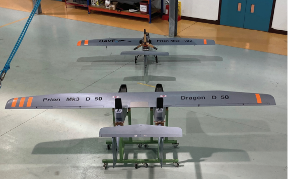
UAVE’s UAVs
The Prion Mk.3 is a STOL, fixed-wing, 3.8 m wingspan UAV, measuring 3 m long, with a typical operating weight of 30 kg and a standard payload capacity of 15 kg (hence a 45 kg MTOW). It is also referred to as the Dragon when marketed or flown in a defence context, or coded as the D15 when flying the standard payload capacity.
UAVE also developed a new, wider wing for the UAV, with a 4.65 m wingspan, which has enabled a 25 kg maximum payload capacity. The aircraft is coded as the D25 for military customers when this wing is installed.
A future D50 is in development, which will have a 100 kg MTOW. All three variations of the Prion or Dragon will run on the DS120 engine.
Fuel capacity, depending on aircraft configuration, runs from 6.5 L to 15 L, with a cruising consumption of 1.1 L/hour at 80 kph airspeed. The UAV typically features a 28×14 three-blade, carbon-composite propeller, mounted at the upper rear of the fuselage.
Key specifications
- DS120
- Single cylinder
- Four-stroke
- Naturally aspirated
- Spark ignited
- Air cooled
- Dry sump
- RON90 gasoline with 2.5% oil mix (JP-8 version also possible)
- Displacement: 120 cc
- Weight: 4.5 kg
- Maximum power: 8 hp (at 4600 rpm with 28×14 three-blade propeller)
- Maximum speed: 5000 rpm
- TBO: 1000 hours (maintenance intervals at 50 hours and 200 hours)
Some key suppliers
- OEM & principal design: DGS Engineering
- Crankshaft balancing: AMB Engineering
- CNC milling & fabrication services: OLLE Precision Engineering
- Metal milling, turning & fabrication services: Fenrich Engineering
- Vapour blasting: Cardigan Powder Coating
- Cylinder heads: JS Engineering
- Valves: G&S Valves
- Fuel injectors: Consolidated Motor Spares B.V.
- ECU: GEMS Performance Electronics
- Exhaust downpipe materials: Merseyside Metals
- Cylinder liners: Laystall Engineering Company Limited
- Specialist metals: Ultimate Metals
- Bearings: Henderson Bearing
- Honda piston components: Vision Spares Ltd (trading as DIY Spare Parts)
- Alternators & power management units: Sullivan Acutronic
UPCOMING EVENTS


