


UAVHE RW1 rotary
Rory Jackson explores two supercharged Wankel rotaries, created using the latest CNC machining tech and innovations leveraged for motorsport two-strokes
UAVHE (Unmanned Air Vehicle Hybrid Engines) is a Barcelona-based engine manufacturer, founded in 2019 by engineers, software developers and computer numeric-controlled (CNC) machine technicians who were connected through high-performance, two-stroke manufacturing for jet skis, ultralight aircraft and paramotoring vehicles.
Andrei Bogdanov, CEO of UAVHE, recounts: “All of us were dissatisfied with the pace of technical progress that these motorsport engines had undergone since the late 1970s. In 2019, you’d still see things like carburettors and poor-quality pre-mixes with terrible emissions.”
Soon after UAVHE began seeking funding, Covid limited them to remote engine r&d. However, shutdowns by other engine manufacturers freed up copious engineering talent to help the group polish its designs through long-distance computational fluid dynamics (CFD), computer-aided design (CAD) and electronic control unit (ECU) programming.
By the time Covid restrictions were lifted and UAVHE began building its factory, its first prototype was already assembled. That morphed into its first product, the PT1-124, a liquid-cooled, crankcase-injected two-stroke, largely based on what the team viewed as cutting-edge tech across motorsport (although today it is offered as a hybrid-electric power plant for VTOL-based or -transitioning UAVs and some crewed aircraft, the company having pivoted over time from motorsport to the vast and growing uncrewed aviation industry).
The development of Wankel-type rotary engines was something that interested Bogdanov and his team for some time, due in no small part to their popularity across ultralights and paramotoring. This motivated them to work on rotary designs and technologies that could overcome the problems typically associated with Wankels, including overheating, poor sealing between internal chambers, insufficient reliability and service life, and performance losses with altitude.
“Reliability and stability are everything, especially for motorsport and professional uncrewed aircraft today. Obviously, power-to-weight ratio, horsepower and torque are important, but if any of those are a bit low, systems integrators can compensate by reducing weight at the vehicle level,” Bogdanov says.
“They can’t compensate for an engine that fails in the field, and the loss of a high-end payload can be tens of times that of the engine. Consider the loss of the mission, especially one in urgent medical deliveries, search-and-rescue or defence operations, and then an engine failure can cause a loss that is priceless.”
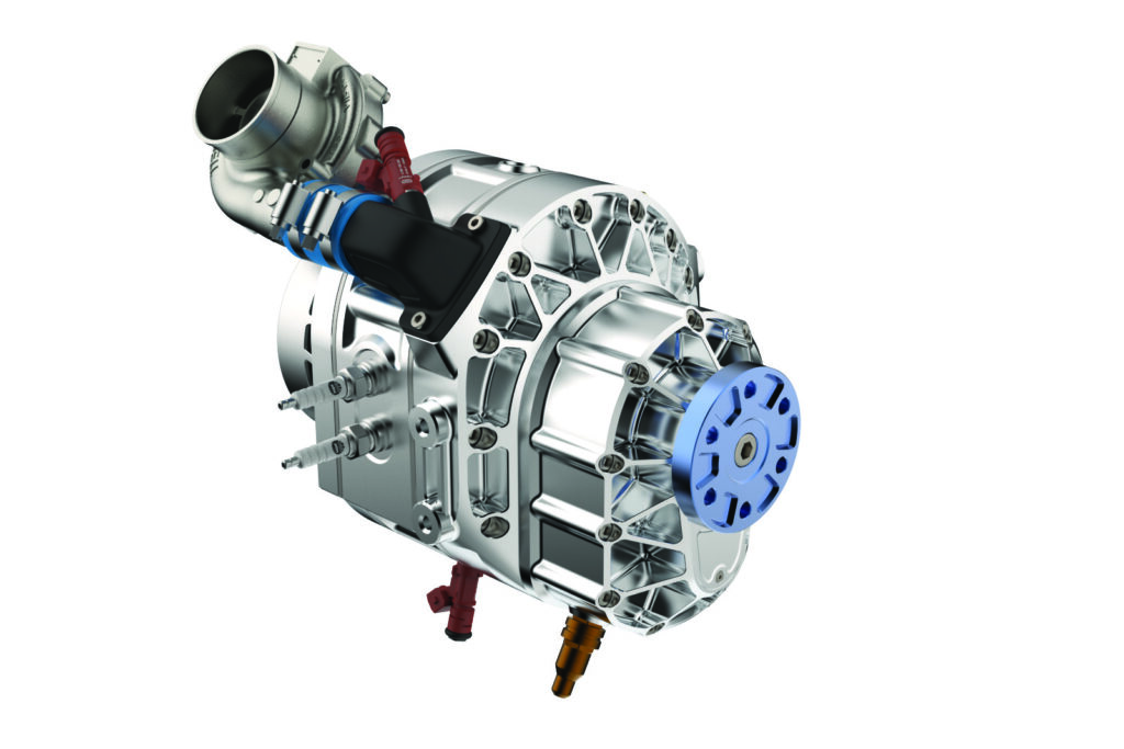
Hence, UAVHE has recently unveiled two supercharged Wankels with forced induction to prevent performance drops at high altitude: the RW1-79, an air-cooled, 22 hp hybrid range extender, weighing 5.2 kg; and the RW1-300, a liquid-cooled, 62 hp engine, weighing 17.7 kg and featuring a gearbox for driving a propeller.
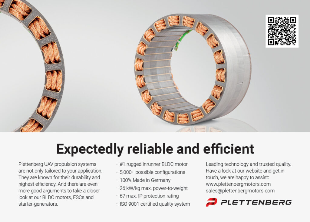
In addition to throttle-less air intake, both engines are single-rotor designs and incorporate UAVHE’s proprietary, two-stage fuel-injection technology, as well as an 11 kW starter-generator and a plethora of judicious metallurgical choices made for optimising reliability.
From two-strokes to rotaries
Metallurgy has been the critical factor in UAVHE’s decision to make the jump from two-stroke engines to Wankel-type rotaries, being core to how it has chosen to address what it viewed as the key problems of traditional Wankel designs. Since its first engine, the company has used atypical metal components; for example, the PT1-124’s single-cylinder liner is cast iron, rather than the conventional nickel silicon carbide.
“Coating the interior of an aluminium cylinder with nickel silicon carbide is a great route to cost-effective engine manufacturing, but it means the cylinder and liner have different coefficients of thermal expansion,” Bogdanov says.
“After around 10 hours of operation with repeated expansion and contraction cycles, microscopic cracks could form at critical points in the liner, and tiny shavings of very hard nickel silicon carbide could then scatter throughout the engine, risking damage.”
UAVHE has opted for cast iron sleeves in its two-stroke cylinders, along with forged aluminium cylinders, heads and crankcases, rather than casting them.
“The cast iron sleeves aren’t cheap and they’re difficult to CNC-machine well, but they can even outlast the forged cylinders they’re placed inside, potentially thousands of hours. They even make for very good lubrication, as the molecular structure of cast iron gives better surface tension for oil than nickel silicon carbide does, as well as more desirable friction and heat distribution properties,” he adds.
To UAVHE’s knowledge, no-one had previously attempted a cast iron sleeve in a rotary engine, but the company viewed the Wankel’s epitrochoid chamber as analogous to a reciprocating engine’s cylinder in certain respects; a typical Wankel uses an aluminium epitrochoid housing with a coating of nickel silicon carbide, or some other ceramic, similar to the use of aluminium and nickel silicon carbide in a piston engine cylinder.
However, while cylinders may be cooler at their intake ports and hotter at their exhaust ports, Bogdanov says: “Wankels have a much bigger thermal differential, as the combustion and exhaust sections of the housing get really hot while the intake and compression regions stay relatively much, much colder. And the border between the hot and cold sections poses an incredibly heavily loaded and difficult to manage part of the engine, maybe the most stressed part overall, so it’s a classic point of failure for nickel silicon carbide-coated rotaries.”
Sealing
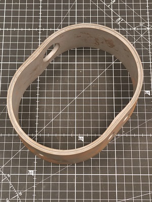
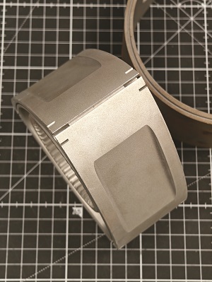
UAVHE has forgone the typical, 400- to 800-micron nickel silicon carbide coating for a cast iron sleeve with a thickness of a few millimetres. This is heavier than nickel silicon carbide, and more costly, as discussed, but as per the sleeves in UAVHE’s piston engines, they are now one of the longest-lasting components in RW1 engines.
“One of the key choices in typical Wankel development is whether to make your apex seals harder than your housing liner, or vice versa,” Bogdanov says. “Most companies choose soft seals, because sooner or later they will make contact with the coating, almost definitely at that point between the hot and cold sections, so they’re choosing for the seals to wear first and to just replace them when that happens.
“But our liner is a monolithic iron piece – we don’t get that expansion-contraction differential, so we don’t have to choose a soft seal. In fact, we get to choose the hardest, longest-lasting apex seal we can to enhance the engine’s time between overhauls (TBO) and the time between maintenance intervals.”
UAVHE’s choice has been a tungsten carbide apex seal, which is CNC-milled in-house from commercially available end mill bits, as these feature a circular and professionally polished outer surface. This gives a curved shape to UAVHE’s seal tips, unlike conventional apex seals, which often feature a square
cross-section at their tips. As they take varying angles relative to the housing wall, the rounded outer shape minimises scraping at the point of contact, and hence friction and wear between the tip and the liner, helping to extend the lifespan of both components.
To date, the RW1 engines have been cycled to just over 690 hours before overhauls, but the company is confident in its projections (based on repeated disassemblies every 20-50 hours to study component degradation) that the two engines’ core components can be optimised to go for 1000 hours.
“We’ve taken several units of our rotary engines apart after 600 hours and inspected them under microscopes – there’s almost no discernible wear,” Bogdanov asserts. “Of course, it takes a lot more tricks than just sealing to get Wankels right in 2024. We do some things with our lubrication and our cooling, for instance, that we’ll get into later. But realising we could do our sealing by leveraging what we’d learned in two-strokes was what motivated us to start cutting metal for the RW1-300, and then the RW1-79 afterwards for smaller UAVs.”
The side walls, or mid-housing plates, are also made from cast iron to ensure all surfaces exposed to combustion and exhaust have the same mechanical and thermal properties. In the RW1-300, a liquid cooling jacket in the housing protects the cast iron against the engine’s higher power combustion temperatures.
Forced induction
A key concern of UAVHE’s regarding Wankels was the stability of their performance across varying conditions, particularly at different altitudes and air pressures, as well as various ambient temperatures. The RW1-79 and RW1-300 are hence electrically supercharged (with no throttle plate or servo), and governed by the ECU, such that a target manifold air pressure (MAP) is maintained across the power curves of the engines.
“To maintain stable MAP from idle to 9000 rpm in a road vehicle amid clutch and gearbox changes is an engineering nightmare, but in an aircraft engine with a constant load and rpm for most flight hours, where you’re really just optimising for reliability and SFC [specific fuel consumption], the eSupercharger works well enough,” Bogdanov says.
“Another reason for electrically supercharging the engines is that our fuel-injection technology requires high-speed airflow to maintain the number and size of our fuel droplets. We’re trying to keep the droplet diameters below 5 microns and our intake port is relatively small, so blowing air and fuel droplets through that very quickly helps prevent condensation.”
Although the benefits of mechanical supercharging have been touted in a few previous issues – such as with DeltaHawk’s DHK180 (Issue 54, February/March 2024) or Flygas Engineering’s GAS418S (Issue 42, February/March 2022) – controlling the supercharger electrically allows the RW1s to be precisely managed for these exact air-speed requirements.
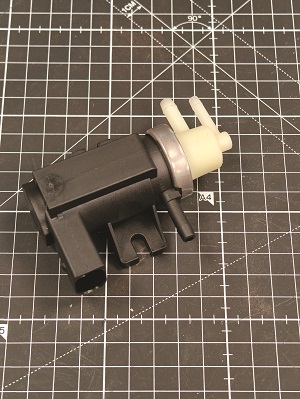
“In the RW1-300, we essentially use a modified Garrett turbocharger, split in half and combined with a BLDC [brushless DC] motor, along with 10 lines of code to create a supercharger that self-balances for MAP,” Bogdanov explains.
“On the RW1-79, we needed to further minimise the delay between accelerations or decelerations in the impeller rpm, and corresponding changes in MAP, so we engineered our own system there.”
The supercharger’s impeller is CNC-machined from a lightweight, forged aluminium alloy, which Bogdanov says is specified for turbine wheels. The RW1-300’s impeller is roughly 5-6 cm in diameter, while the RW1-79’s is 2-3 cm.
“In both engines, we consume up to half a kilowatt of power to run the supercharger, but we’re able to generate an easy surplus of electric power from the 11 kW generator anyway, and because we maintain a positive pressure from the intake port to the combustion chamber, we get benefits in fuel atomisation, SFC, thermal stability and reliability that more than pay for that power usage,” he notes.
Rotor cooling
The intake is the key contributor to the RW1 engines’ rotor cooling function. This is a perennial and arguably underappreciated aspect of successful Wankel design, as insufficient rotor cooling can rapidly lead to engine failure (as the combustion chambers and their rotors’ needle bearings are typically only millimetres apart). To date, the challenge has been resolved quite differently by each Wankel engine manufacturer featured in this publication.
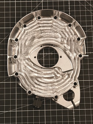
In the RW1-79 and RW1-300, the intake port is a rectangular opening on one of the sides of the housing’s end plates, but the ensuing air channel does not go directly into the Wankel intake chamber. Instead, air is routed through a lemon-shaped aperture in the middle of the plate and passes into the apexes of the rotor.
Before doing so, injectors for the first stage of fuel spray, as well as oil injectors, both sitting in the intake channel, dispense their fluid droplets into the air flow. Hence, the rotor is charge-cooled in a method that bears a small resemblance to Rotron’s approach to rotor cooling in its naturally aspirated RT600-LCR (Issue 49, April/May 2023), although it now leans towards its RT600-HC for its use of a Venturi-style exhaust ejector to increase the speed with which charge moves through and cools the rotor.
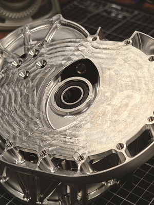
As for the RW1 engines, once the supercharged air-fuel-oil mixture enters the rotor apex, it makes a rotation loop, lubricating and cooling the inner wall of the rotor, as well as the main bearing, and the internal and stationary gears.
“Inside the ‘pocket’ of the rotor’s inner chamber, centrifugal force presses and accelerates the oil and charge, pushing into an array of very small channels, CNC-cut about the apex seals and treated with diamond-like coating [DLC], so those are cooled and lubricated too. Then the mixture exits the rotor through a bypass channel and goes into the combustion chamber. We heavily CFD-optimised the mixture path loop so combustion occurs at an optimal front,” Bogdanov says.
“DLC isn’t cheap, but it ensures the rotor is strong and hard enough at the points where it holds our apex seals. Those channels exhibit no measurable wear after hundreds of hours of operation, despite tungsten carbide being one of the hardest substances manufactured today.”
Given that another perennial issue of Wankel engines is internal oil leaks and hence oil consumption, even when they are designed with their rotor bearings sitting in an oil bath, supposedly sealed from fuel and air, UAVHE has opted for the two-stroke approach of mixing oil into the fuel, such that the oil can contribute to cooling and then burn up, instead of contaminating the rest of the engine via blow-by or other leakage.
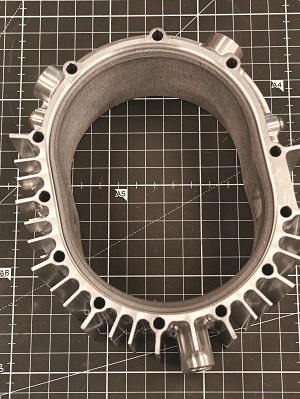
The cooling of the outer housing is far more straightforward in both engines. The RW1-79 is cooled by air flow, with the supercharger pulling its intake air via the electric motor, and the latter’s rotor dispersing part of that air into the channels and ribs about the engine housing. Those heat-sink structures are geometrically optimised via CFD and thermal FEA to compensate for the non-uniform heat distributions of Wankel engines.
The RW1-300, being a larger and higher-power engine, is liquid-cooled using a standard, water-glycol jacket running internal to the housing mid-plate. It typically integrates with dual-redundant cooling loops, radiators and pumps, the lattermost devices having variable capacities to ensure temperature optimisation during flight and a controlled rate of cooling after landing.
Fuel delivery
In addition to the first stage of fuel injection shortly after air enters the engine, a second stage is sprayed directly into the combustion chamber, precisely calculated for speed and position about the twin spark plugs. The RW1s (as with all UAVHE engines) integrate a proprietary fuel-injection system.
“It is similar to how inkjet printers distribute ink,” says Bogdanov. “We’ve built the system module around a matrix injector that can mechanically alter the focal length and width of the spray nozzle, and it’s around 100 times faster than conventional injectors in its ability to control outputs of droplets.

“That allows us to closely control the size of each droplet, and hence control fuel pressure, which hugely helps us achieve the ideal fuel/air mixture and high-quality combustion conditions. The ability to maintain such conditions, including the ideal MAP via our supercharger, was something we wanted to be sure we could achieve before we started cutting metal for rotary engines.”
Each module features nine injectors (in a 3×3 matrix) and functions, such that each column and row can be rotationally actuated to control the spray angle. This also helps control droplet size, as thanks to UAVHE’s CFD modelling of airflow inside the chamber, the ECU can aim a given injector to spray into the airflow to ensure a particular coagulation or dispersion of fuel henceforth.
“To improve fuel burn, the second fuel stage doesn’t involve just one fuel spray per rotor compression,” Bogdanov says. “The internal volume of the Wankel combustion chamber changes at each moment of the crank rotation, and not in the relatively simple way that reciprocating engines’ spaces between piston and cylinder head change, so the curve of the air/fuel mixture over time resembles a letter ‘m’, to keep the air/fuel ratio efficient and stable.
“In essence, the changing shape of the Wankel combustion chamber is such that when the first stage of air/fuel mixture from the intake channel starts to burn it creates a back-pressure wave, causing imbalances in the air/fuel ratio along the intake cycle. Hence, we compensate for that with a second, calculated set of fuel sprays. It helps us to run the engine leaner overall than if we relied purely on that first, manifold-injected stage.”
Combustion and control
The spark plugs are surface-discharge, platinum-coated devices, customised in-house for long life. While the engine could work perfectly well on COTS NGK- and Bosch-type plugs, Bogdanov notes the latter types would not last as long.
“Much more work went into ignition control. We’ve a sensor and an internal back loop for gauging whether gas ionisation in the chamber post-combustion is above or below where we want it to be, as anything from a spark-plug error to an injector mishap to an air bubble in a pressure regulator can cause discrepancies,” he says.
“So, maybe on one rotation the combustion is incomplete, meaning there are leftover fuel deposits in the chamber; based on what the ECU detects, it can fix that by skipping one of the next fuel-injection stages or targeting a leaner fuel/air mix. And we re-gauge every rotation to precisely re-optimise until gas ionisation and combustion conditions are normalised.”
Mapping for this and other re-optimisations by the ECU took extensive simulation (including 2D mathematical modelling, 3D CFD analysis and structural FEA) in Ansys and Matlab, followed by bench-testing measurements.
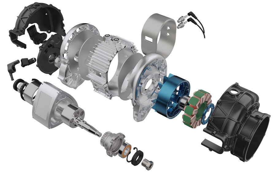
Power componentry
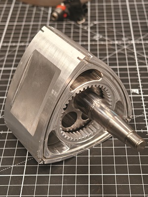
The rotor is cut from the same forged aluminium as the supercharger impeller, and the side walls (including the combustion pocket) are also treated with a form of DLC, though of a different type to that in the apex seal grooves. Rather than producing the internal gear separately and installing it afterwards, it is integral to the rotor, being cut from the same aluminium billet before being thermally treated and surface coated.
“That has been a controversial choice, having an aluminium internal gear that interfaces with a steel stationary gear, but we’ve run a lot of experiments showing that the geometry of our internal gear teeth distributes the contact from the stationary gear across a wide enough surface that there is no excessive wear,” Bogdanov says.
“We cut the rotor as a monolithic part to get that precise geometry, whereas if we’d used a steel insert, it would be much harder – some find it impossible – to perfectly align the gear and teeth into the rotor such that the internal and stationary gears line up for optimal contact distribution and minimal wear. It’s expensive and complex to cut the rotor so finely, but modern CNC techniques make it possible.
“Having an all-aluminium rotor makes it lightweight, reducing secondary [longitudinal] imbalances in the engine. Of course, the shaft has a counterweight, but there is always some secondary difference between those two counter-rotating masses, so making the rotor lighter reduces the engine’s vibration output.”
The eccentric shaft is cut from forged steel, and polished and plasma-treated at its bearing mounts, with three standard ball roller bearings per shaft (two on the front end, one at the rear). The remaining gears are cut from the same steel.
“We deliberately use slightly oversized bearings and mounting points, just to hold the shaft as rigidly as possible, and because we may produce dual- or triple-rotor versions of the RW1 engines someday. A shaft designed three times longer would naturally need extra bearings to hold it steady,” Bogdanov adds.

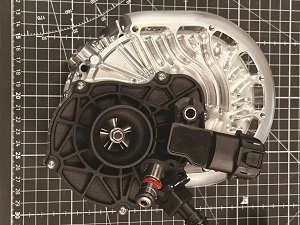
Gearbox and propeller
While the RW1-79 is not designed for propeller output, the RW1-300 integrates a two-stage gearbox with a wet centrifugal clutch. Typically, this does not engage until at least 3000 rpm at the eccentric shaft, and the standard reduction ratio is 1:3.2, but the engagement point can be preset on the ground as per user requirements.
The oil bath is sealed. Sensors for temperature, viscosity and metal shavings, installed at ports around the gearbox housing, instruct the user on oil replacements rather than relying on a rough hourly count.
“Each cog is CNC-milled from a proprietary material on our DMG MORI CTX machine, and given thermal and chemical surface treatments, such that the gearbox produces almost no noise and does not represent a key point of failure for the 300 engine. We’ve yet to suffer a gearbox fault in any test, including lubrication, overheating or overloading failures,” Bogdanov says.
“We’ve oversized the bearings and some of the gears, but that makes for a very rigid structure. Outside of the housing, we’ve designed quite large fins so that the front functions as a radiator for the gear oil.”
An electric variable-pitch propeller is typically installed on the gearbox’s output shaft, with a 52° swing range, and a transfer time of less than three seconds for the blades to move from their start to end positions at maximum load.
Generator
In both the RW1-79 and RW1-300, the 11 kW motor-generator is directly driven off the back of the eccentric shaft. The system is a BLDC outrunner design, constructed in-house.
“As well as starting the engine from a dedicated, 5 A starter battery, and providing power for the main batteries and subsystems, it also functions as a smart flywheel on the 300,” Bogdanov says. “As some will already know, Wankels’ torque curves over shaft rotations are uneven – torque rises quickly at the ‘power stroke’ right after combustion but drops during the compression right before that.
“To compensate, we measure the revolution timing via a crank position sensor and engage the generator following combustion, drawing slightly from the power and torque to charge a bank of supercapacitors. Then, when the power stroke ends and we’re at a trough in the torque curve, we release the load from the generator, switch it to a motor mode, and return some of the stored energy back to the motor and hence to the shaft.
“That flattens out the torque output, relieving a lot of stress and vibration from the gearbox, the propeller and other components. Our power management includes torque balancing even if the end-user chooses to use the hybrid system for prolonged boost power to the propeller; energy drawn by the motor to power the shaft will be less pronounced during the power stroke, and more pronounced during intake and compression.”
UAVHE’s smart flywheel technology was originally developed for two-stroke paramotor engines to minimise vibrations transmitted through to the paramotorists’ backs, while the high power and hybrid aspects of the technology were first innovated for jet skiing.
Power management
“On top of those features drawn from our motorsport engines, we’ve further configured our electrical output around the most common type of project that our engines get installed into nowadays – VTOL-transitioning, fixed-wing UAVs with lift motors mounted on twin booms,” Bogdanov says.
Upon startup, the engine drives the generator to charge dedicated lift batteries (a common feature in today’s hybrid-quadrotors), while the gearbox clutch prevents the RW1-300’s power getting sapped by the propeller.
“Then, electrical output from the motor-generator is delivered via four controllers, each with four output channels, so 16 output channels in total. If more channels are desirable, we can just add more controllers,” Bogdanov says.
“Each channel forms a 48 V connection, but they can be combined for 96 V, 144 V or 192 V connections, and so on, and the channels are assigned prioritisations to ensure some components keep receiving power, no matter what. For instance, the autopilot, flight surfaces and maybe the payload in some missions should never lose power.
“But, some other systems, like ESCs [electronic speed controllers] for the lift motors, wing-mounted LEDs or some companion computers, aren’t critical to the UAV’s survival, and so they can be prioritised lower, so that if there’s something wrong with the engine or the system is overloaded, the ECU can cut the lower-priority groups to save the aircraft.”

Engine management
UAVHE’s ECUs are dual-redundant, featuring two identical PCBs, designed to comply with FAR 33 airworthiness standards, the company anticipating that future UAV engine regulations will be modelled around them.
“To ensure those standards were met, the ECU was completely designed and built in-house, with every line of code coming from a blank sheet and not from any particular sort of open-source ECU software, and all industrial- or automotive-grade board components,” Bogdanov asserts.
“All connectors and busbars were Amphenol mil-spec or aero-spec parts, while the main microcontroller is a fairly standard ARM chip. We run embedded software on that in two layers: one is our RTOS for the core functions of engine performance, and the other is more of an application layer, with a Unix OS running system health monitoring, statistics, data logging and network-related tasks, like controlling the CAN and Ethernet buses around the engine that the sensors, fuel injection, ignition and supercharger rely on.”
Bogdanov notes that running two layers of ECU software on a single chip is rare, but this is primarily due to automotive rules made in the 1980s, designed to prevent overloading the far lower-power chips of that time. These days, chips are far more powerful and capable than most regulating bodies realise, to the point that fuel, air and electricity mappings about the engine and generator can be recalculated at least once, sometimes twice, per shaft revolution.
The ECU is designed with inputs for tracking the level, pressure, flow, temperature and viscosity of the fuel, and to have multiple of each sensor placed at different points along the
fuel-delivery system to discern whether the fuel has frozen or a filter has clogged. Additionally, a MAP sensor is integrated as standard, along with sensors for manifold air temperature and humidity.
Onward and upward
Having validated the RW1 engines in dynamometer tests, cycling them in environmental pressure and refrigeration chambers, as well as vibration tables, while scanning them with high-speed and infrared cameras to study for mechanical and thermal performance, UAVHE is now looking towards production numbers. It anticipates scaling back manufacturing of its piston engines in favour of its rotaries.
“In terms of new products, we’ve done a few projects in jet engines and have learned what it takes to make ECUs, fuel injectors and so on for those, so we’re hoping to show some hybrid turbojet designs by 2025,” Bogdanov says.
“We’re also planning to diversify into making helicopter transmission parts, from swashplates to rotor heads. It will need some skilled specialists, but in most cases the overall helicopter powertrain loses a lot of its quality if it uses an engine, a transmission and a rotor from three different manufacturers without a common telemetry, common design approaches and so on.”
UAVHE is also investigating the use of sustainable aviation fuels (SAF). Neste in Finland has provided some samples for testing, while Repsol in Spain has produced a bio-kerosene formula that Bogdanov cites as producing “great” performance in his company’s engines.
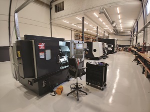
Meanwhile, at UAVHE’s manufacturing plant, raw materials and finished components are being closely tracked along production lines, with QR codes for exhaustive traceability and quality control logging.
Its production machines include 5-axis and 9-axis CNC milling machines from DMG MORI, with additional CNC metal cutters from Haas and other companies, as well as laser etching machines for the surface texturing of iron sleeves to improve oil distribution across some components.
“Haas’ machines come with a control system they’ve made in-house, so operating them is quick and intuitive. Their control hardware advances slowly, but their software gets optimised and hot-fixed very quickly,” Bogdanov says.
“Bigger brands often use something like a Siemens Fanuc control system, which is well-made but problems get fixed really slowly. With Haas, by contrast, I once asked them to add some M-code to extract some data. They did so, and through that my machines now send me notifications based on entirely custom data triggers.
“I’ve been working around CNC manufacturing for the last 20 years, and the progress I’ve seen over the last five to six years has been amazing. I know there’s endless buzz about additive manufacturing, but multi-axis CNC machines can now be used to mill really complex shapes with more precision than ever. I honestly feel like we’re in a golden age of CNC production in which hardware simply isn’t a limiting factor anymore.”
Specifications
RW1-79
- Wankel rotary hybrid
- Range extender
- Single rotor, charge- and oil-cooled
- Electric supercharger
- Two-stage fuel injection
- Forced air-cooled housing
- Weight: 5.2 kW
- Dimensions: 162 x 177 x 193 mm
- Effective displacement: 79 cc
- Power: 22 hp
- Maximum generator output: 11 kW
- Fuels: JP1, JPA, wide range of automotive and aviation gas
- SFC: 240-260 g/kWh
- Maximum continuous speed: 13,000 rpm
- Oil: API TC
- TBO: 690 hours tested, 1000 hours expected
RW1-300
- Wankel rotary hybrid
- Gearbox with centrifugal clutch
- Single-rotor, charge- and oil-cooled
- Electric supercharger
- Two-stage fuel injection
- Liquid-cooled housing
- Weight: 17.7 kg
- Dimensions: 330 x 280 x 280 mm
- Effective displacement: 298 cc
- Power: 62 hp
- Maximum generator output: 11 kW
- Fuels: JP1, JPA, wide range of automotive and aviation gas
- SFC: 250-260 g/kWh
- Maximum continuous speed: 9500 rpm
- Oil: API TC
- TBO: 690 hours tested, 1000 hours expected
Some key suppliers:
- Spark plug ceramic insulators: NGK
- Electrical components: Amphenol
- CAD software: Ansys
- CAD software: Matlab
- CAD software: Solidworks
- CNC machines: DMG MORI
- CNC machines: Haas
- CNC machines: Starrag Bumotec
UPCOMING EVENTS


