


Keybotic Keyper
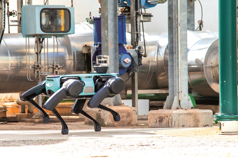
Rory Jackson charts the development of this quadrupedal robot designed for risk-laden heavy industrial facilities
The three Ds – dull, dirty and dangerous – have for some time been applied to the kinds of jobs that industry is eager to delegate to uncrewed systems; that eagerness is now spreading from outdoor applications to indoor ones. The indoors of heavy industrial facilities such as oil rigs, factories and warehouses can be particularly dangerous places, given the risks posed by chance explosions, chemical leaks and so on.
However, despite the need to replace people in such environments, uncrewed systems geared for doing so are rare, and with good reason. Heavy industrial facilities are not designed for wheeled robots to travel through them easily, owing to obstacles such as pipes, cables, doors and steps.
UAVs can offer an alternative here, but they raise issues with loud rotor noise, exposed propeller blades and short mission runtimes, so they are rare as well. Legged robots offer a solution though. A UGV that can walk could navigate obstacles as we do, whether it be a pipe, a staircase or a worker-filled corridor.
Hilario Tome, CTO of Keybotic, has a lot of experience with UGVs, having worked on commercial bipedal robots as well as full-on autonomy through the virtual category of DARPA’s third Grand Challenge.
Its first two challenges were aimed at accelerating self-driving car technology and small teleoperated materials-handling robots. The third was the first subterranean challenge, in which remote operations via wireless links were out, and true autonomy was in. The winner would be whoever could build a robot most capable of working continuously, reliably and intelligently beyond the reach of human intervention.
“I knew that for robots to take the next great leap, they needed to be smart enough to understand where they’re working, and to navigate that environment,” Tome recounts. “Many people had Roombas [robot vacuum cleaners] by that point – they work great, but they’re confined to planar surfaces and small, static areas.
“A dynamic, 3D environment brings an explosion of problems, and it made me realise I wanted my next project to be a robot that solved all those challenges but remained affordable.”
This ideal solution in Tome’s eyes was an autonomous quadrupedal robot. He knew that, compared with bipedal types, quadrupeds are inherently easier to balance, control and automate their perception and navigation, bringing a compounding effect in cost reductions and ease of use. These are among the biggest reasons for the successes of ANYbotics’ ANYmal (issue 40, October/November 2021), Ghost Robotics’ Vision 60, and Boston Dynamics’ Spot.
Although the subterranean challenge had started a year prior to Tome joining, and he was competing against larger, better-funded organisations entirely by himself, he remained confident.
“I’m a controls guy, and this third challenge was one of estimation – estimation and controls are practically the same thing mathematically. In control, you’re looking into the future to understand how to get somewhere, while in estimation you’re looking into the past to understand where you are in the present, so it was easy from my perspective.
“I won first place in the virtual competition and received $1 million to fund the company and product I wanted to create, to build a few prototypes and get feedback from potential customers.”
That win came in late 2021, but Tome had begun concept work on his ideal robotic solution several months before that. What emerged is a quadrupedal UGV known as the Keyper, which is designed for autonomous operations in a range of hazardous indoor environments, and draws on what he and his team have learned from robotics above and below ground.
Engineering philosophy
The Keyper is a 43 kg robot, which is a compromise between Tome’s team wanting the system to be as light as possible and the largely fixed mass of the system’s batteries, motors, electronics and metallic structural parts.
The system is fully electric and runs for about 90 minutes between charges, with a 40 minute fast-charging time, although Keybotic plans to offer a slow-charging option in the future for users who are conscious of battery maintenance costs and the benefits of making batteries last longer.
It can walk at up to 2 m/s (7.2 kph) on its four legs, but that is too fast for industrial complexes, so typically it is rarely higher than 1 m/s.
Rather than undergoing defined iterations or phases, the Keyper’s engineers have repeatedly tuned and upgraded its subsystems using a more evolutionary approach.
“If we’d designed this uncrewed vehicle to be modular, we’d risk making individual sections or even the overall design sub-optimal, because you can make mistakes like oversizing compartments, fittings or joints to make detaching or replacing subsystems easier,” Tome explains. “With this robot we’re dealing with a major challenge in terms of actuation, for which we can’t afford any sub-optimal decisions.
“Industrial robots are precisely controlled for positioning, but generally they’re not made to resist impacts. With the Keyper though, we want it to resist impacts and regulate the force it imparts with its legs.
“When you walk, when successful robots walk, there’s little precise control of leg positions. What we’re really doing is controlling the way our limbs interact with the floor and where we place them.”
To achieve fine control of locomotive force, Keybotic had previously used harmonic drives (also known as strain wave gear systems) with custom-built torque sensors for turning the high speed of their actuators into high torque, as is common in robotics; impacts however will cause these to break easily. The company notes two conventional approaches for countering this: a spring to absorb impacts, or a clutch so that the reducer can slip in moments of excess torque.
“Both introduce extra components and hence points of failure and expense however,” Tome comments. “So Louis Mouzet, our principal mechanical engineer, decided we’d design a totally new and unbreakable actuation and gearing system ourselves.
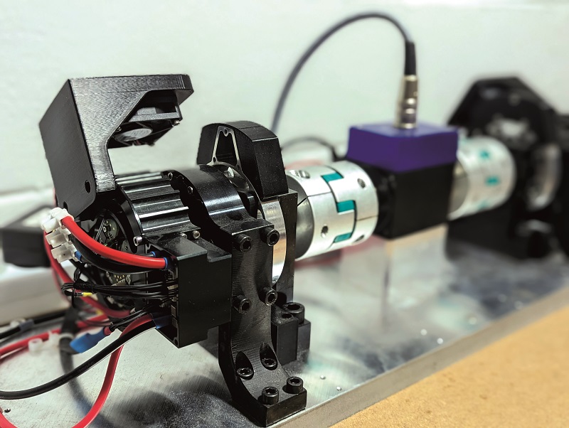
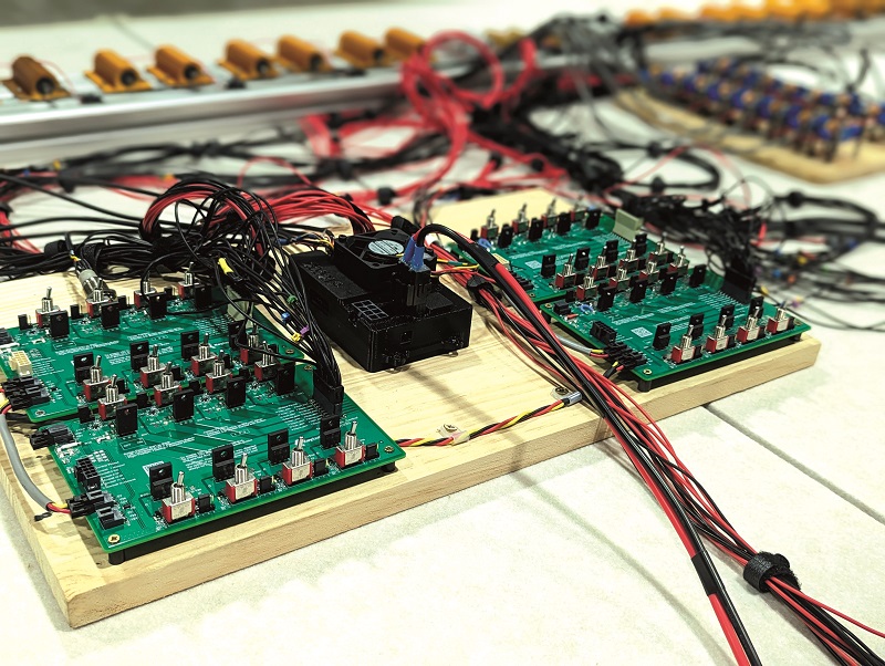
“That took a few months. Building an actuator requires building a complex test rig and stressing each version of your actuator beyond its limits between five and 20 times, then finding breaking points to inform your next version. We might not have gone for modularity with the Keyper, but in our proprietary actuator we had a modicum of modularity, swapping motors, gears and sensors to evaluate what was best.”
Once it was satisfied that its actuator was optimally reliable and could control the leg output force effectively, the leg was optimised around three such actuators, and a test rig was built in which the leg could be subjected to repeated shocks and other forces while stationary or jumping for many hours.
Then came the design and engineering of the body, it being a cuboid that at first simply had to sit between four of the leg units. Once that was done it was fastened with four legs, and the prototype was ready, just 6 months after Tome had assembled his team in late 2021. Since then, the team has iterated the subsystems, gradually moving towards tighter integration, optimising for intelligence and efficiency.
The Keyper’s architecture
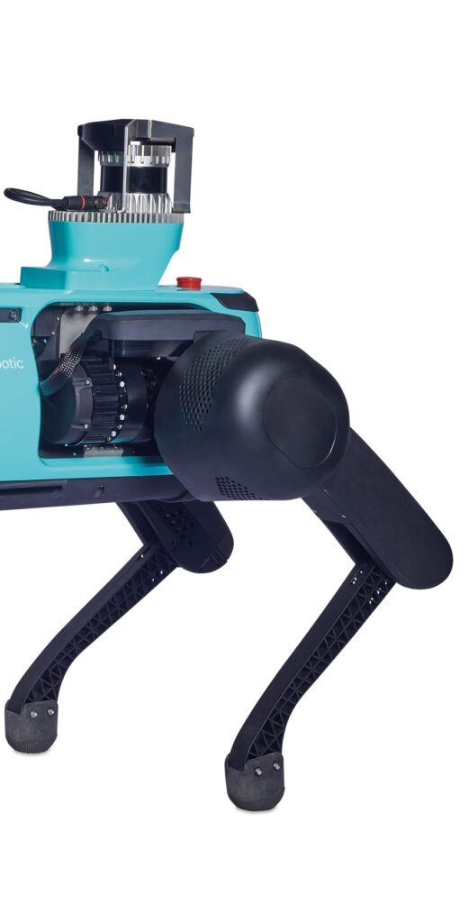
In determining the balance of components between the Keyper’s body and its legs, Keybotic has sought to minimise the number of them inside each leg, as a lighter leg means lower inertia, enabling it to move faster to help maintain its balance.
As a result, the Keyper’s body contains all the hardware for sensing, processing, comms and energy storage, with the legs storing only the actuators.
Energy is stored in a lithium-ion battery and distributed to the rest of the robot via a power control board, with a charging receptacle on the underbelly. Two Intel 12th-generation CPUs form the Keyper’s core processing ‘brain’, one of which is broadly dedicated to deterministic tasks such as locomotion and the required perception, and the other to asynchronous functions such as task planning, optimisation and arbitration of routes, and user code.
“Customers will need their own code for integration purposes, and we didn’t want them to install their own companion computer, as allowing the Keyper to run with untried additional core hardware could risk changing its behaviour, so we’ve provided extra processing space and bandwidth by having two Intel CPUs,” Tome explains.
The exception to this rule are multi-sensor inspection payloads, which are commonly used in industrial inspection and are designed as plug-and-play devices that can therefore be run at the edge of the network without affecting the robot’s core behaviour. There are three payload connectors on Keyper’s back, each being a 24 V power and signal D-Sub rectangular connector, with an additional Ethernet connector for sensor data.

Actuating a leg
While tighter integration has been the long-term goal in the Keyper’s engineering, the legs are detachable. Each one mounts to the body via four screws, so that in the event of damage the customer can replace the leg themselves.
“It would be tempting fate to say the legs will never fail, but they can be replaced easily, minimising the system’s downtime,” Tome says. “That said, we’ve sought to maximise the ‘transparency’ in the actuation.”
In this context, transparency refers to the accuracy of the output joint torque across all three actuators and the gearing that follows.
“For electric motors to work well in a leg, you need a trade-off between speed and torque, but you will lose efficiency in the process, as well as the resolution with which you can control the motor’s force output,” Tome says. “That is unless you do what we did, which was to make a gearbox good enough for you to trust the estimated torque output at the robot’s feet based on extrapolations from the motor power and speed readings.
“That took a lot of iterations on the gearbox’s design, the gear materials and the construction of custom test rigs for validating the efficiency of our reducers. We’d measure their performance, stress them, then collect and analyse the test data points until we were satisfied we had the most efficient gear reduction possible.
“Of course, we’d get closer torque measurements by just using a torque sensor with a measuring spring or strain gauge, but we’re not doing surgery, we’re just trying to control how the leg interacts with its environment, in order to control the impedances. As people, we don’t know how much force we produce when we step, but we feel the impedance once we’ve set our foot down, and that’s what we then regulate.”
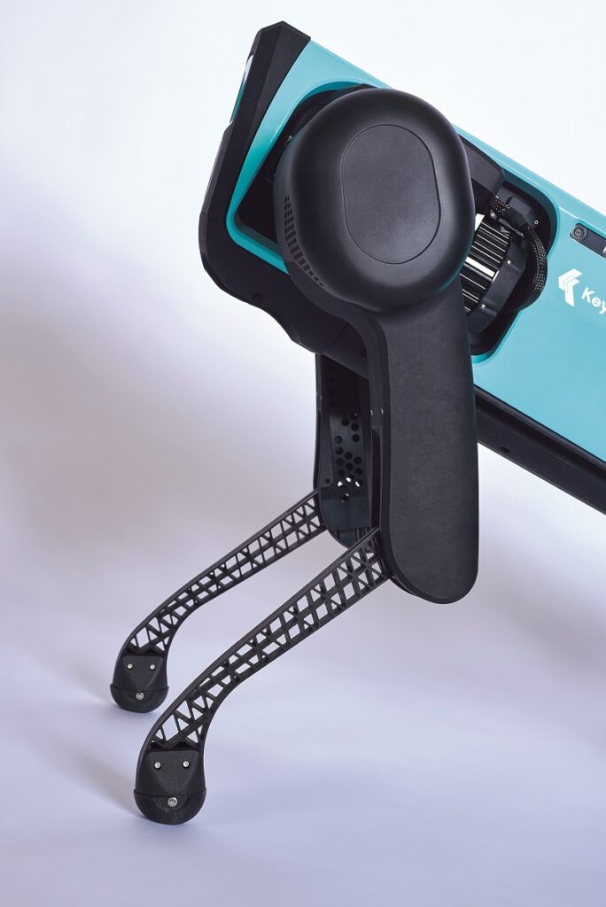
In addition to its patent-pending gear system, the actuator has been designed for a balance between simplicity and robustness. All three actuators per leg are identical, and assembled in-house from 35 mechanical parts, which collectively comprise the controller board, motor and gearbox, each of which can be produced using simple processes such as injection moulding or three-axis CNC milling, avoiding the need for five-axis milling or additive printing.
Although most animals’ limbs have four planes of actuation, installing three actuators has proven sufficient for giving each Keyper leg three degrees of freedom; the fourth point gives animals the ability to orient their legs in order to plant their feet carefully. In bipeds, a fifth actuator, in the ankle, is necessary for angling the foot, but for the Keyper, orientation of the leg matters little, as the ‘foot’ is essentially a rubber ball.
Starting with the UGV’s hip, first there is an actuator oriented for rotating in the x axis, as this can be socketed within the body’s footprint. Just outward from that is the y axis actuator, for sidestepping motions (or abduction) while lower down but in the same plane is the knee joint.
“Some robot designers put the knee joint very close to where they need the output torque, but if a heavy limb moves quickly, it adds excessive inertia to the moving mass of the robot, increasing the energy needed to stop the moving limb,” Tome says. “We want to minimise the energy needed to move the legs and increase their agility, so we’ve avoided doing that.”
The ESCs currently sit by the actuators, but in the final version of the Keyper they will be integrated inside them. That will help simplify the design by having the leg as a comprehensive, contained system, minimising wiring tasks during maintenance, and safeguarding motor control signal integrity by minimising wire lengths between each motor and its controller.
“Each ESC needs five connections into the leg: three for the motor, two for the encoders for position feedback,” Tome notes. “We could eliminate a lot of wire by soldering the ESCs directly onto the motors and encoders.
“We’re discussing who to use as our ESC supplier, the key thing being maximising the controller’s power-to-size ratio. RLS provides our encoders, and we’ve found their units are available across a wide range of precision levels. Encoder resolution correlates directly with price, which made it easy for us to choose the right solution for our needs.”
Structural aspects
Keybotic has chosen aluminium for every feasible structural need, as it is inexpensive, lightweight and easy to manufacture compared with composites and other metals. To further that, the Keyper’s engineers have stuck to a narrow range of aluminium alloy types and aluminium suppliers. 7075-T6 is predominant for its widespread availability.
“When something structural bends in a robot, it’s either because of the material or the shape of your design, so we’ve focused on optimising key stressed areas of the structure to mitigate that,” Tome says.
“The legs’ attachment points suffer the most severe loads, so we’ve designed reinforcements there with some very particular steels using FEA. Essentially, wherever there’s a stress problem, we reinforce it with a small amount of steel.”
He adds that all FEA is performed in SolidWorks, for its ease of use and affordability. “FEA has evolved to the point that you can really trust it, particularly for things like large, reasonably stationary body panels,” Tome says. “In a system like ours though, there are so many moving parts, which means friction, backlash and other variables you can’t model, so you can’t be sure you’ve designed the right structure until you’ve built and tested it in different walking scenarios.”
Walking intelligence
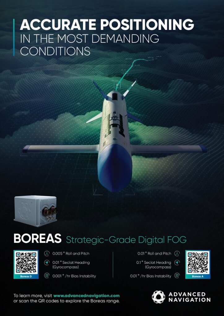
The primary basis for the Keyper’s intelligence, walking stability as well as navigation, is an AHRS. An IMU alone would have fallen short of sensing requirements, as Keybotic needs the UGV to always understand where it faces, so attitude and heading are key, on top of acceleration and angular rate.
“We chose Advanced Navigation’s Orientus as our AHRS,” Tome says. “We have many estimator algorithms embedded in the robot, and we could have developed our own AHRS, but we’ve found that Advanced Navigation’s system outputs the heading so consistently and easily that it removed a lot of headaches for us.”
The Orientus MEMS device weighs 25 g and consumes 0.5 W. Its magnetic heading readings are accurate to 0.8o, with 0.2o accuracy in roll and pitch, a 3o/hour bias instability, and it has a 1000 Hz update rate.
“We also need to perceive and digitally reconstruct the surrounding environment to calculate the necessary movements for reducing stumbles and impacts,” Tome explains. “Fortunately, just 10 m of forward optical range is sufficient for a good safety margin at the speeds the Keyper travels.”
Using Lidar for perceiving and modelling the robot’s surroundings would have been cost-prohibitive, so Intel RealSense D455 stereo cameras are used instead. The D455 combines the company’s D450 camera module with its D4 vision processor board, along with a Bosch BMI055 IMU and a USB-C 3.1 (Gen 1) connector for straightforward power and data interfacing.
Its stereo cameras provide an FoV of 87 × 58o, with a frame rate of up to 90 fps and a resolution of up to 1280 x 720 in its output depth footage. It also integrates a 1 MP RGB sensor with global shutter and a 90 × 65o FoV.
“We use five of these, covering 360o around the robot and creating a representation of the world for the Keyper so that it knows where to step and how to avoid bumping into obstacles,” Tome says.
The cameras include one D455 pointing left, one right, one rearwards and two forwards. The second forward camera tilts slightly downwards, for awareness and resolution of obstacles or physical inconsistencies such as cracks or uneven stairs that could otherwise threaten the Keyper’s stable forward movement. It also enables perception redundancy in the direction the Keyper will most often travel in.
Navigation intelligence
Tome notes however that performing localisation using vision alone is extremely challenging, because the resolution of range measurements and the availability of distinct visual features is often unreliable for triangulating position within a known area.
“That’s the thing about stereo cameras, they’re depth estimators, they triangulate depths and distances based on visual markers and the perceived differences between those from one ‘eye’ to the other,” Tome says.
“They don’t know in a tactile way how far away or apart objects are, so in lieu of computationally intensive optimisations to localise without consistently available visual markers, we’ve mounted an optional Lidar on the Keyper’s back to detect precisely where every point of every surrounding surface is, regardless of how featureless a given room or corridor might be.
“We weren’t always sure we would opt for Lidar. Tesla among others weren’t wrong in the past to think relying on Lidars would make autonomy too expensive to be commercially viable, but Lidar prices have dropped dramatically, to the point that there’s really no excuse not to use one, given that one is enough for localisation.
“If you analyse the increases in the various metrics for robustness that Lidar gives you, and measure those against the increase in the cost of the product, there’s no question that it’s worth it.”
Tome has opted for Ouster Lidars since his days in the DARPA challenge, and its 500 g OSO-32 Wide Range Lidar is now typically mounted on the Keyper.
It generates 1,310,720 points per second, at a maximum data rate of 86.55 Mbit/s, with a 90o vertical FoV (360o horizontal). Each point includes a measurement for range, reflectivity and azimuth angle among other parameters, along with a timestamp usually within 1 µs.

“As well as Ouster building its product on many proprietary technologies, its Lidar has a really big FoV, scattering its points very far with each shot, and that’s crucial to triangulating our position at all times,” Tome says.
First-time users can provide the Keybotic with a pre-made map of their industrial environments, which can be uploaded to the UGV as a localisation reference source. However, the company recommends that an on-site inspector guides the UGV around using a remote control console so that it can perform stereo camera and Lidar measurements of its surroundings, and use its computer vision to recognise and annotate critical objects such as gauges, valve wheels and so on for future reports.
“That way, the Keyper gains way more information than many pre-existing digital twins,” Tome says.
“To have as layered a virtual environment as possible, we use a multi-modal sensor fusion system,” he adds. “If a sensor breaks down, the others act redundantly, and if something is hard to discern in one, chances are you can verify it with another.
“It’s a complicated approach for sensor fusion, especially if you have different suppliers or teams for different sensors, but as I programmed the interfacing between everything myself since DARPA, and we have so many sensors complementing each another, it made complete sense for us.”
Indoor autonomous robots are often limited to sparse maps with fixed navigational waypoints and highly automated behaviour, with little or no capacity for deviating from pre-programmed paths, even where prudent. Such is the detail of the Keybotic’s generated environment however that the resulting 3D map enables the Keyper to perform real-time autonomous waypoint changes and path repetitions or double takes, without operator interventions.
“Of course, planning a path through a map with a billion cells is impossible, but just as Google Maps determines routes first by searching through each state, then by city, then by street, rather than looking at every single block and street in its database, our representation takes a similar top-down approach to job requests once it has a complete virtual representation of the operating environment,” Tome says.
Intel and EtherCAT
As mentioned, the Keyper’s main computer uses two Intel 12th-generation systems, each of which contains an i7 1260p CPU and a GPU. As well as being the latest in Intel’s processor portfolio during the UGV’s development, it contains multiple cores designed for different speeds, so that separate embedded software programs can run at just the rates they need while still operating in parallel with each other.
“Our deterministic control computer needs to process many tasks,” Tome says. “Some of them require really high frame rates, some just need parallelisation, and this combination of efficient cores and normal cores has produced a really good system for us.
“I’ve not seen this type of segregated compute architecture outside Intel, and I wish they were offered more widely. It’s not dissimilar to how CPUs and GPUs have been established in their different roles as platforms for software in autonomous robots, and in fact we use the GPU that comes with the Intel board for some key image processing tasks.
“We had to do a fair amount of kernel programming, but luckily we’ve built a lot of kernel modules in the past, so there wasn’t a lot of trial and error. We had to play around with frequencies a lot, as heat in a CPU increases quadratically with frequency. If you max-out your speeds to get a really quick-thinking robot, you’ll basically have a toaster.”
EtherCAT is used for the primary comms bus in the Keyper’s computer network. Initially it was chosen for its bandwidth which, Tome notes, often exceeds the Keyper’s operating requirements, making it a safe bet when development began for future-proofing against bandwidth scarcity.
It also provides cable redundancy in the network, among other features. These ancillary capabilities are not used yet, although Keybotic regularly looks into whether extra reliability or efficiency might be gained through them. Those, combined with the ability to seamlessly link multiple systems for real-time determinism, sensor fusion and diagnostics, confirmed this choice by Keybotic’s’ engineers.
The EtherCAT protocol contains many proprietary elements, so users typically supply their ASICs to Beckhoff Automation (one of the main vendors of EtherCAT), which then integrates its interfaces into the ASICs. While this takes away much of the transparency and control available through other buses such as CAN, the user gets far higher bandwidth, among other benefits.
“In a CAN bus, you have messages zipping up and down through every node in a system, and those all have to be synched for timestamps,” Tome says. “That synchronisation requires triggering every node, all at once, all the time to recognise what messages they’re receiving and when.
“But EtherCAT has one single message that travels to every node. It goes to one actuator, which writes it down, then it goes to the next, and that writes it down too, and so on until it loops through the entire bus, back to the control computer. You can’t do that at a high rate unless you have truly insane precision in how your protocol is built.”
Power management
A 48 V bus transmits battery power. Higher voltages would result in lower current losses in the servo motors, but also higher speed relative to torque, some of which would be lost through the gearbox in any case, making them unnecessary.
“It’s even less necessary for our processors, as high voltages can also mean losses when transistor gates move, so we don’t stick with 48 V for everything,” Tome says.
“Our principal electronics engineer, Nicolas Murguizur, has built some DC-DC converters in-house to meet our packaging needs. The sensors, computers and other electronics have their respective voltages below 48 V, but the ESCs and servo actuators do receive the 48 V output.”
To guarantee electrical safety, a red emergency stop button sits at the back of the body, and an electronic emergency stop is also programmed in. This is a remote shutdown triggered through the power monitoring and distribution board, where voltages, power consumption and other health-critical parameters are tracked.
This is also where the DC-DCs are mounted, although Keybotic might simplify its power distribution board in the future, particularly if customer trials show that the amount of health data being tracked is surplus to requirements.
“We’ve had to design some custom connectors to plug and disconnect each leg easily via a single cable, and to route power and data through that,” Tome says. “There are some great connector suppliers who will do excellent quality hybrid power-and-data connectors for you, but often they are designed for critical cases like aircraft, military vehicles or medical equipment. That would have driven up the price of the Keyper a lot.”
Energy and recharging
The battery contains 500 Wh and is assembled in a thin, longitudinal shape to match the body’s shape and for symmetrical weight distribution, as well as good balance for the centre of mass.
“We interface with the BMS through a Modbus protocol; our supplier has been doing this for 30 years now and has a plethora of safety certifications,” Tome says. “We told them how many cells we wanted and the shape of the pack, and they soldered, packed and sealed it with the BMS inside, as well as putting in the Modbus and power connections.”
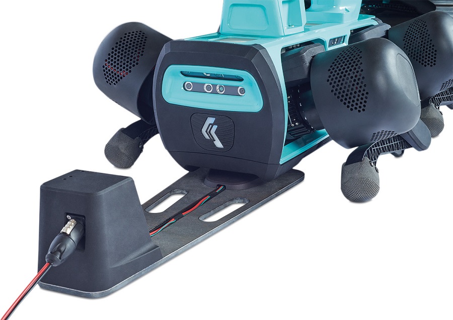
The charging station on the robot’s underbelly works as a docking receptacle. A Keyper walks over a charging station, kneels and mates with the connector for recharging to begin.
In the future however, Keybotic intends to switch to wireless charging. “The industrial environments where Keyper is expected to work are prone to high amounts of dust and other ambient contaminants,” Tome says. “To prevent ingress into the charging system, other walking robot chargers use mechanical trapdoor systems, but that just adds moving parts which are bound to fail eventually.
“Wireless charging reduces the system to a receptor antenna and an emitter antenna, and everything’s fully sealed against dust. There are no mechanical parts that can fail, or any chance for dust to get into the trapdoor’s mechanism or any other part of the charging system.”
Operator systems
The Keyper’s 2.4 and 5.8 GHz wi-fi antennas are identical to those in consumer PCs, mounted topside in a gap in the aluminium to prevent transmissions being blocked or interfered with, as well as COTS 4G modems with built-in antennas for cellular comms, which Keybotic does not modify.
“Our wi-fi can also be used in dual mode, so if a user has both a 2.4 and a 5.8 GHz network, it can connect to them separately. For instance, one can go to an independent GCS and the other to the company’s network infrastructure,” Tome says.
The UI software has been designed in-house to make the robot easy to use by untrained personnel. It comes in the form of an app that is meta-compiled to be accessible from any smartphone, tablet, laptop or desktop, although Keybotic anticipates it will eventually move to a web-based interface to prevent users having to install new software on company hardware.
“It’s the most frictionless option, provided we comply with all the cybersecurity laws,” Tome says. “And because our software’s meta-compiled for all these platforms we don’t have to change a single line of code for it to work on the web.
“Also, regarding cybersecurity, we use all the proper firewalls and VPN tunnels to keep our system closed. That can make it harder for users to change things about it, but opening your software can bring vulnerabilities, so we won’t do that until we move to a web-based model, when it’ll become necessary.”
AI systems
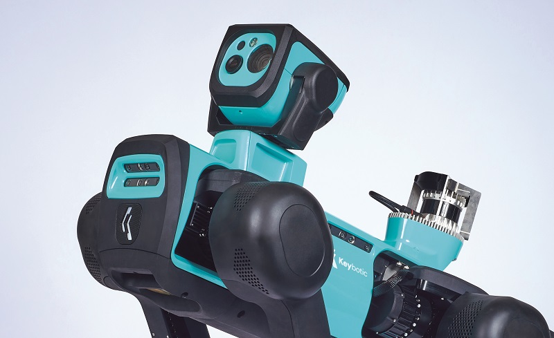
As mentioned, inspection heads connect to the top of the Keyper through a single D-Sub connector with power and data pins. The standard inspection head includes a 30x optical zoom camera, a thermal camera, an acoustic sensor and a torch, as well as a gimbal designed to stabilise the view for inspecting distant targets at maximum zoom.
The stereo cameras are designed for depth sensing and short-distance 3D modelling, not high-resolution inspection, hence the inspection head will provide all the high-zoom or wide-angle HD imaging data.
“Many companies making this type of robot will rely on third-party analysis software, which is expedient, but the more complicated the robot is, the harder it is to make a success of what those parties tend to provide, so we’ve written our inspection head image processing components from scratch,” Tome says.
“Neural networks are key to the Keyper reading gauges and analysing data, and because we want the payload to be a modular, independent system, the necessary computing power is also packaged inside.”
To that end, an Nvidia Orin Jetson is installed in the inspection head, it being necessary for processing power to read and understand gauges. Overall, the head weighs 4 kg.
“And in terms of training the robot to walk correctly, our current control algorithms were developed entirely through model predictive control [MPC],” Tome explains. “This was the state of the art until maybe 2 years ago, but since then ETH Zurich, Oregon State University and the University of British Columbia have all demonstrated some game-changing stuff with reinforcement learning [RL] in legged robots.
“We’re now running RL algorithms on the Keyper and carrying out experiments with that, but what we’re using in customer facilities is the MPC, and in the end we expect some hybrid algorithm using both will win out. The performance of the walking gait of the robot using a learned algorithm is proportional to the hours spent training it, not those coding it, so there are benefits to be drawn from the work we’ve done with both.”

Future plans
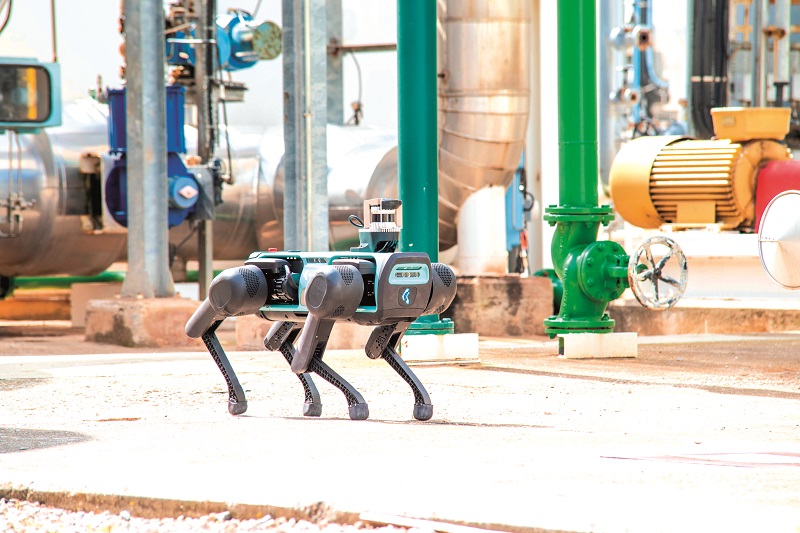
The Keyper is now available for industrial use. Its first publicly named customer is Carburos Metalicos, which supplies industrial and medical gases to the Air Products Group.
Since the start of June 2023, Keyper has been inspecting the infrastructure of Carburos Metalicos’ 12,000 m2 plant in El Morell, Spain. Its sensors provide close analyses of the various gauges and other key equipment, and its locomotion and balance have been crucial to handling the many stairs and uneven terrains of the facility.
Aside from a few small modifications and optimisations depending on how technology evolves, the Keyper is a largely mature and complete solution, although Keybotic is tempted to produce an ATEX-certified version – one approved for work in areas with explosive hazards – given the industrial customers it targets.
“The problem with ATEX certification is you have to be absolutely certain you’re happy with the design once it’s certified, because you’re not allowed to change a single screw after that,” Tome says. “Once we’re satisfied with that we’ll embark on an ATEX project.”
Keybotic already has a sensor for measuring the explosivity of an environment, and is therefore prepared to work close to ATEX zones. But while ATEX operations are a valuable niche market, and clearly within the company’s capabilities, being asked not to evolve a design permitted to enter such zones is anathema to the very spirit of innovation that drives the world of uncrewed systems.
Specifications
- Keyper
- Quadrupedal UGV
- All-electric
- Full weight: 43 kg
- Maximum endurance: 90 minutes
- Charging duration: 40 minutes
- Maximum speed: 2 m/s
- Operating speed: 1 m/s
Some key suppliers
- AHRS: Advanced Navigation
- Lidar: Ouster
- CPUs: Intel
- GPUs: Nvidia
- Stereo cameras: Intel
- Encoders: RLS
- CAD/FEA: SolidWorks
UPCOMING EVENTS


