


Electric Flytrain EFT-Hybrid-1x
The founders of this UAV engine developer have brought their expertise in the EV world to bear on building a heavy-lift UAV power unit. Rory Jackson reports
From EVs to UAVs
As the automotive world becomes increasingly dominated by electric and hybrid vehicles, expertise and technology transfers from the EV/HEV space stand to make small aircraft powertrains more efficient. To our knowledge, Electric Flytrain (EFT) is the first company to spring from the EV world into that of UAVs, but then its three founders were all active in the automotive industry during the great shift towards electrification of a new generation of passenger cars to come over the next few years.
Tobias Kahnert, CEO of EFT, says, “I worked on electric powertrains at Tesla for 5 years, from back when the Model S was first coming out, through to the time when we saw the technology quickly maturing and coalescing into the Model 3’s release as a mass-market car.”
His two co-founders worked at BMW and Siemens at the time, and collectively the three designed all the parts encompassing a complete electric powertrain, including the firmware design, battery design and sensor development.
Recognising how technological development and maturity were accelerating in the electric and hybrid world, the three foresaw how aviation would also eventually go electric. Although significant regulatory and supply chain hurdles still stand between them and an electric aircraft industry to supply powertrains to, they determined that in the meantime, UAVs represented the perfect beachhead market.
By designing and supplying highly efficient electrified powertrains to the professional UAS industry, they could hone their engineering expertise and use that to conceptualise what the perfect powertrain for eVTOL, eSTOL and other electric aircraft types would one day look like.
“We soon realised that the gravimetric energy density of batteries is still a problem for aviation,” Kahnert says. “You quickly hit a physical limit when trying to achieve a long-range flight with a heavy payload using batteries alone, even if an all-battery powertrain is appealingly simple.”
EFT has therefore sought to develop its first product as a plug-and-play hybrid-electric solution principally for heavy UAV manufacturers, with the aim of combining the maturity, power density and energy density of an IC engine with the ease of use of an all-electric solution, in addition to having lower emissions compared with an IC powertrain.
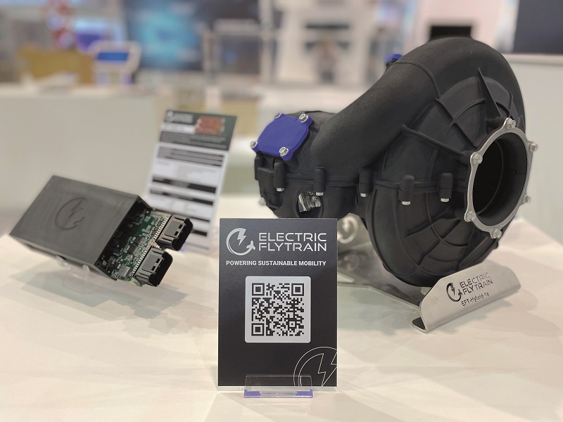
That first product is the EFT-Hybrid-1x, a 19.5 kg gasoline-electric series-hybrid powertrain, which produces 11.7 kW of continuous electric power. It has no intended shaft power, as its primary customers are manufacturers of multi-rotors and other all-electric UAVs seeking higher endurances than batteries alone can offer.
The IC engine at the core of the solution has a specific fuel consumption of 290 g/kWh and is produced by Salzburg-based engineering company HC-Concepts, which also provides key development support across prototyping, testing, and industrialisation for EFT.
The engine is a modification of what HC-Concepts refers to internally as the AX250. This is a four-stroke, spark-ignited two-cylinder boxer running on gasoline.
However, as EFT’s engineering is aimed at providing an electrified product, and as HC-Concepts is not principally a UAV engine company, we will focus here more on the electric componentry in the powertrain, as designed by Kahnert and his team, along with some critical contributions from Acutronic Power Systems, formerly Sulllivan UV.
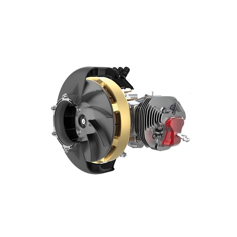
The most visible of these components in the Hybrid-1x’s configuration are an alternator – the preferred nomenclature from EFT and Acutronic, rather than ‘generator’ or ‘motor/generator’ – which is mounted on the output shaft in front of the engine, and a forced-air cooling system mounted in front of and around the alternator (as well as over the engine cylinders).
Downstream from the alternator are a power management unit (PMU) that connects with the alternator, rectifies its AC output into DC (and can invert DC to AC to power the alternator for starting the engine), and is mounted wherever the end-user thinks is prudent in their UAV. The DC supply from that goes to a battery pack which is managed by a BMS. Lastly, a Hybrid Control Unit (HCU) developed by EFT acts as the master controller for the powertrain.
“We are optimising the Hybrid-1x for UAVs with a MTOW ranging from 70 to 150 kg,” Kahnert adds. “Switching from batteries to our powertrain with a prudently sized fuel tank should extend their flight times from 20-30 minutes to multiple hours, making it possible for them to rival crewed helicopters in long-endurance applications such as aerial logistics, surveillance and search & rescue.”
Powertrain concept
The company chose a hybridised gasoline four-stroke boxer configuration, principally to ensure that only mature, tried-and-tested technologies were incorporated into its first product. The route of hydrogen for instance, be it a fuel cell or hybridised IC engine running on hydrogen gas, was not taken because not every component would have been matured enough and have the availability to satisfy EFT to allow the stability of production and maintenance of such power systems.
“However, subsystems for hybrid-electric IC powertrains are widely understood, and their supply chains are quite stable,” Kahnert says. “That was the first best guarantee that we could achieve our goal of putting together an efficient turnkey package that would integrate easily and work consistently.
“We also researched powertrain configurations that were popular across the UAV market, and found four-strokes to generally offer a higher measure of durability than two-strokes. That was really important if we were to achieve a reasonable parity with all-electric powertrains in terms of reliability.
“There will be some higher maintenance because it’s undoubtedly more mechanically complex than a straight battery-ESC-motor set-up, but we still wanted to limit the extent of that as much as possible.”
After selecting HC-Concepts as the engine supplier, EFT proceeded to design its solution as a series hybrid, with as much of the shaft power as possible being turned into electrical power via a shaft-mounted alternator.
This approach, as opposed to a parallel hybrid or others with an open protruding shaft, would allow EFT to produce a power unit that could serve multiple UAV configurations and save end-users the work of optimising their UAVs for the relative quantities of shaft and electrical output power (or vice versa).
That would also be the ideal choice for EFT’s target customers. To further optimise its solution for these users, the EFT-Hybrid-1x is also designed with an active thermal management system, with a forced-air system for keeping the combustion and electrical components at safe temperatures in the absence of any rush of cooling air.
“That takes the cooling burden off our end-users’ shoulders, which becomes especially important during extended hovering periods when the engine and alternator will experience high power demands for prolonged times,” Kahnert says. “The cooling system therefore took up a huge part of our testing and iteration focus to ensure the whole powertrain could be kept within a safe temperature range, even when running at full continuous power.”

Development timeline
The company’s first research into promising hybrid powertrain technologies started in January 2021. Around 5-6 months later, Kahnert and his colleagues had largely agreed on their preferred configuration and key partners, and the first proof-of-concept prototype was being tested on a workbench by autumn 2021.
That produced copious data on ways to optimise the solution, particularly in terms of customising and improving the various components to work together as if they had all been designed by a single integrated powertrain OEM.
“That pushed us into our next phase, for our second-generation prototype, for which we started working very closely with HC-Concepts,” Kahnert explains. “That helped us really improve the HCU.”
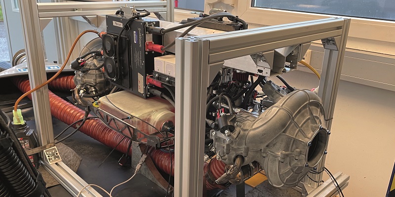
The second prototype was ready for testing by April 2022, after which EFT began the packaging stage, in which all the powertrain components were integrated into a physical form that could conceivably be sold as a product, including fuel tanks and power connectors. This was completed in November 2022, and at the time of writing the company was carrying out endurance testing and preparing for flight testing to verify its performance targets and mature the complete system.
“About 50 hours of endurance testing have been completed, to prove-out the EFT-Hybrid-1x’s long-term performance capabilities, identify failure points and optimise or mitigate them to eventually identify and guarantee a minimum TBO,” Kahnert explains. “It also allows us to work through our maintenance routines and see how well the packaging and integration lend themselves to quick detachment and replacement of parts.”
EFT is also on the lookout for suitable pilot customers who they can engage with to develop versions of the Hybrid-1x that are optimised for real-world use cases. It anticipates that the UAV market is more likely to want small batches of customised powertrains than bulk orders of COTS systems.
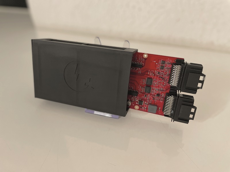
Hybrid Control Unit
The HCU – also called the EFT-HCU-1x – is the master controller for EFT’s hybrid powertrain. Much like most of the ECUs we have previously discussed, it is the central receiving point for all the data collected from the sensors across the EFT-Hybrid-1x. Based on the processed readings, it transmits commands to control vital powertrain subsystems to achieve performance and safety targets, as needed by its own mapping and by the autopilot (with which it maintains a constant interface).

Considerable work has also gone into tailoring the HCU’s firmware for calibrating it to the power requirements of the customer’s UAV platform, given that different UAVs will have different arrangements of motors, motor controllers, flight controllers and connections. When the HCU initialises it will therefore run through a number of pre-processing checks on subsystems such as autopilots, ESCs and electric rotors, and calibrate or even rewrite its software modules to ensure the engine, alternator, PMU, battery and cooling system all run in a way that is tuned to the flight and power profiles of that particular UAV.
“This includes things like appraising performance and health data from the UAV manufacturer’s records to set alarms for platform-specific motor winding temperature limits, maybe with escalating levels of alarms so they can know the degree of urgency with which maintenance is needed, or know when landing immediately is a safety imperative,” Kahnert says.
The master controller principally had to be capable of communicating with the sensors and lower-level controllers throughout the EFT-Hybrid-1x. “Typically, the comms between the HCU and the UAV’s flight controller is over CAN 2.0b, with our own suggestions for layouts and content of messages combined with any additional information packets that the end-user wants,” Kahnert says.
“The BMS is then typically also connected via CAN, and the PMU outputs data over RS-232.”
Interfaces for UART, SPI, I2C, PWM and more are also available on the HCU, along with an SD card for logging data at a high rate from incoming sensor connections, for real-time monitoring and long-term maintenance tracking.
The sensors include seven high-temperature thermocouples across the engine for measuring temperature across the cylinders, heads, exhaust and oil system, with an additional stator-mounted temperature sensor for the alternator and two battery temperature sensors. The engine also integrates sensors for lambda, fuel flow and fuel level.
Alternator
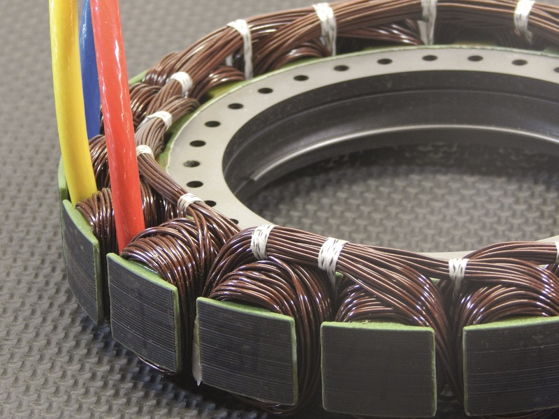
The alternator is supplied by Acutronic Power Systems, and provides both the electric current for charging the battery and a starter functionality for the engine. It is a derivative of the company’s S676-800U-02.
As Kevin Peryea, chief engineer at Acutronic, explains, “The S676-800U-02 is a 203 mm-diameter starter/alternator, it’s designed with 18 slots in the stator, 22 magnets in the rotor, and uses a lot of the materials used elsewhere in our product line. However, we have improved on the typical silicon steel laminations by moving to a higher performance, higher quality and thinner silicon steel lamination, as EFT are running it at high continuous revs to achieve the Hybrid-1x’s high output level.”
He adds that the permanent magnets used in the Hybrid-1x’s alternator have remained the same as in the standard version: a high-temperature neodymium, specifically the N45SH(T) grade. An aircraft-grade aluminium, 7075-T6, is also used in the construction of the rotor – again, standard for this alternator and across most of Acutronic’s alternators.
“When building the alternator we use a commercial, high-temperature electrical insulation system rated for heat levels up to 200 oC, which makes it safe for the electric machine to run up against the IC engine and also keeps its own heat from spreading to other systems,” Peryea says. “We design our alternators to be as efficient as possible but there are always some heat losses.
“Because we pull upwards of 8 kW out of the alternator continuously at about 50 V, the amperage is really high, so we hand-wind the copper wires in our stators to maximise the fill ratio. We worked with EFT to adjust the winding scheme to match their targeted operating performance, and of course everything else about the alternator and PMU must also be matched to the engine’s performance, or else we risk overloading the engine during start-up or failing to generate electricity efficiently.”
The hand-winding enables small modifications to parameters such as the voltage constant, with three iterations of the alternator having been produced over the course of r&d. That is influenced by the data EFT accumulated from its motor test benches, not only on the three-phase output from the alternator but also on the DC output from the PMU.
Such testing investigated the alternator’s torque at low rpm to optimise starting behaviour, measured its electrical output at peak shaft horsepower to ensure the choice of alternator was neither too small nor too big and heavy, and checked that the kV rating – the correlation between rpm and three-phase output voltage – was paired with the operating voltage for the intended vehicle platforms.
“And through CAD, we were able to play with things like the alternator’s diameter, whether it should be an inrunner or outrunner, and whether the magnets were surface-mounted or interior-slotted to the rotor, all of which were critical to laying the foundations of how our powertrain would operate,” Kahnert comments.
“Ours eventually became a system where the stator is in the centre and the rotor wraps around it, as that makes for better torque than the alternative. The windings were key to controlling the relationship between voltage outputs and rpm levels, both in starting mode and electricity generation mode, as that really comes down to the thickness and number of turns of the stator wire. You can have thicker wire and fewer turns to get lower voltage and higher current, or use thinner wire with more turns to increase voltage and reduce current.”
With each iteration of the alternator delivered by Acutronic as per EFT’s requests, EFT also worked with independent testing facilities to gain detailed evaluations of power curves and efficiency ratings at different voltages, in order to inform the next iteration.
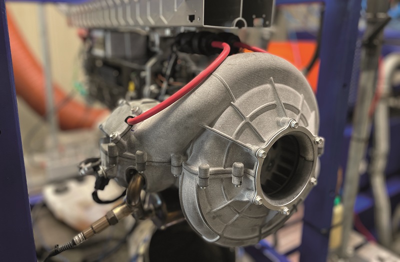
Forced-air cooling
As heat rises in electric powertrains, efficiency rapidly drops, and as multi-copter UAVs are generally either slow-moving or stationary, they rarely experience or produce sufficient airflow to cool their power systems using anything other than the downwash directly below their propellers, so the EFT-Hybrid-1x uses a forced-air thermal management approach.
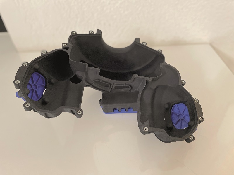
“At the heart of it is a cooling fan design, which consists of fins mounted straight onto the outrunner rotor with a housing around both,” Kahnert explains. “That allows us to use the rotational speed of the crankshaft and rotor to drive the fan as an air impeller. It pulls air into the housing and through different spiralled channels, so some air goes to the alternator and some to the cylinder heads.”
This means that in principle, the cooling system is similar in concept to those installed on ULPower’s UL350iHPS (issue 45, August/September 2022), and by Ishikawa Energy Research in its ARE opposed-piston series hybrid (issue 30, February/March 2020). Both used cooling fans driven directly by their crankshafts, with minor differences – the former was not a hybrid, and the latter had two crankshafts and hence two fans.
“By having a very efficient and targeted set of pathways for the air, we make sure we only cool the systems that we need to cool, and dissipate their heat in as concentrated a way as possible,” Kahnert says.
“The housing around the fan and alternator forms a critical part of the cooling, as its geometry and outlets dictate the flow rate and mass of air going to the alternator and heads. Crucially, its frontal aperture integrates a filter that prevents particles and moisture from reaching the alternator.”
Dassault’s CATIA was initially used to design the housing and the fan, and simulate how air could be pulled, collected and redirected to the hottest areas of the powertrain. It also helped to determine how this could be achieved without undue leaks of air elsewhere across the system, as that could induce unwanted vacuum or pressure effects across the engine or UAV.
As CATIA’s simulations fleshed out the design concept, the results were increasingly exported to and run in Ansys for more detailed analyses of how targets such as more energy-efficient air suction could be managed. This second set of simulations was indispensable for optimising the thermal management, especially in retuning the fins (or blades) of the fan and the air distribution channels for efficient high-volume intake of air and cooling of the cylinder heads.
“That’s not necessarily just because the pull of air was sometimes inefficient,” Kahnert adds. “Without exhaustive simulation, it would have been really easy to make the fins too big and induce a load of parasitic losses on the crankshaft, and hence waste energy at the shaft level even if we were saving some at the thermal level.”
SLS (selective laser sintering) additive manufacturing (AM) was also vital for quickly testing and iterating the cooling system, particularly as the SLS machines could print structures using polymers that are stable at 200 oC. That meant the fans and housings were not only technically accurate demonstrators that could be integrated and tested on the powertrain and dynamometers, but also viable at a production level, given the complex air channel shapes the SLS machines are suited to making.
“It helped the speed of our iterations that there are only three parts to the cooling system,” Kahnert notes. “The fins are printed as part of a plate that mounts onto the rotor, and the housing consists of an upper and lower shell, with the cooling passages integrated into the two halves.
“In the future, it might be even easier to make those components through injection moulding, assuming we make them from plastic. We’re open to metals or composites, particularly if we get a build or use case with much higher temperatures, but we’d still need the fine geometric sophistication that AM offers.”
Power management
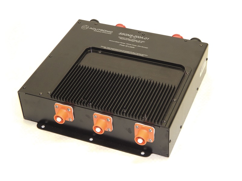
Acutronic also supplies the PMU, which is a customised version of its SSGNS-200A-01. It has been developed through collaboration between EFT and Acutronic, with customisations being concentrated on the control logic, voltage outputs and thermal management.
It incorporates a rectification unit for converting the alternator’s AC output into DC to charge the battery. It also provides the means by which the engine throttle is governed in order to manage the voltage.
“Operationally, the first function the PMU provides is actually to use the operating battery power to start the engine,” Peryea explains. “We have logic and a series of controls in the rectification unit that will manage the entire engine start-up process from the perspective of the throttle. When it’s given a command from the HCU to crank the engine, it sets the throttle to the right position for starting, then cranks the engine by back-driving the AC alternator with power from the batteries.”
Kahnert adds that the HCU communicates with the PMU via an RS-232 connection, and essentially sits one level higher up than the PMU, the BMS and the ECU for the AX250 engine.
After that the PMU activates a ‘warm-up mode’, which is pre-programmed and can be customised for different engines and customers, and targets a specific rpm to enable the engine to warm up without placing any load on it. Eventually, the warm-up mode gives way to a voltage tracking mode, in which rectification is performed and the throttle servo is advanced or retarded to achieve the desired output voltage.
The HCU supervises this mode, monitoring key health indicators such as data from temperature sensors across the powertrain to determine whether operations can safely continue, or transmitting data indicative of poor powertrain health to the flight controller to signal whether an emergency descent is needed.
“That comes with several feedback loops that the PMU also monitors for gauging safety levels. One of them monitors how much current goes into the battery, to make sure we’re not sending too much and risking an overcurrent or associated damage,” Peryea says.
“We’re also checking we don’t draw too much power from the engine and cause it to stall. Otherwise, the demand on the system could actually run much higher than the hybrid powertrain can supply.”
For thermal management, the PMU has been designed with a thermally efficient selection, layout and packaging of board-mount components, as dictated by Acutronic’s discussions with EFT, with heat dissipation typically also achieved by mounting it within the flow of the forced-air cooling system.
“Speaking of those board-mount parts, at the time this system was being designed, there wasn’t a perfect MOSFET that could perform optimally in both a starting functionality and a rectification functionality,” Peryea recounts.
“So we have one bank of MOSFETs that drives the starting mode – they are very robust in order to handle the spikes of hundreds of amps when cranking the engine – and then we have a second bank of MOSFETs that run more efficiently when running at lower current levels.
“The latter are ideal for rectification, because they’re better tuned for getting every last bit of current out of the alternator and into the battery with minimal losses, which is what you want most in a hybrid arrangement. Our component selections, design layout, timing and switching strategies are all oriented around optimising efficiency.”
Battery and BMS
The battery is a 14S1P pack, with 800 mAh of capacity, and consists of cells tuned for high discharge so that the pack can deliver high power during emergency descents lasting up to 2 minutes or possibly longer.
In addition to storing electrical energy and delivering it to the UAV, the battery also powers the alternator to drive the crankshaft during start-up. It also balances the peaks and troughs of power received from the PMU, which can be particularly critical for instance during strong gusts, when a multi-copter’s rotors must suddenly run at very high power to try to maintain its position.
While the engine’s crank speed and electric output will accelerate slowly relative to the rotors’ speeds, the battery’s energy will last until the alternator output catches up, and continue absorbing the surplus power after a gust has passed.
“The battery itself comes from Maxpower, while we’ve designed the BMS along with the full junction box that comes with it,” Kahnert says. “That contains a relay for switching the battery in and out of the powertrain, like an automotive HV interlock switch, and the HCU controls that relay. The junction box also allows us to distribute power to different downstream subsystems across the UAV by way of different voltage dividers.”
While UAS batteries are smaller and therefore safer in many regards than those Kahnert and his colleagues encountered in the EV industry, temperature management is still critical for preventing issues such as overheating during an emergency descent, or under-temperatures when the IC engine is not running and suddenly needs to be started. In addition to mounting the pack away from any potential sources of heat (or puncturing), the BMS therefore had to be developed with greater safety and thermal stability than those in all-electric UAVs.
“Designing the BMS was made easier though by the fact that many typical BMS functions were already handled elsewhere in the powertrain,” Kahnert says. “For instance, we were already tracking the incoming current, outgoing current and the voltages through the PMU.
“Similarly, the HCU already ran battery temperature sensors. So tasks left to the BMS included individual cell voltage measurements and balancing.”
Future plans

Development of the EFT-Hybrid-1x is ongoing, and as mentioned the company continues to seek and accumulate partners for performing the first rounds of flight tests, after which it will look to bring the powertrain into productionisation.
“We don’t just want to fully productionise it ourselves and then show it to the market; we want to define the production line in cooperation with pilot customers, because everything about UAV powertrains down to the most minute details is so heavily defined by niche end-user requirements,” Kahnert notes.
As well as manufacturing and supplying its UAV powertrains in the long term, EFT also plans to provide full maintenance services for its customers and maintain component stocks in-house for the fleet managers who buy from them.
Specifications
- EFT-Hybrid-1x
- Series hybrid
- Four-stroke, two cylinder boxer
- Spark-ignited
- Gasoline
- Naturally aspirated
- Shaft-mounted, PMAC alternator
- 14S1P battery pack
- Lithium-ion cells
- Weight: 19.5 kg
- Maximum continuous electrical power: 11.7 kW
- Specific fuel consumption: 290 g/kWh
- Maximum fuel consumption: 3.8 kg/h
- Maximum battery capacity: 800 mAh
Some key suppliers
- IC engine: HC Concepts
- Alternators: Acutronic
- Inverters: Acutronic
- Batteries: MaxPower
- CAD: Dassault
- CAD: Ansys
UPCOMING EVENTS


