


Taurob Inspector
(All images: Taurob)
No sparks fly
Rory Jackson reports on this ATEX-certified inspection robot, carefully engineered to handle explosive environments, indoor navigation and staircases without any fireworks
Today, more companies than ever are open to using robotic and autonomous systems for dull, dirty or dangerous work, but when it comes to gaining clearance for tackling the dangerous, uncrewed systems engineers are tasked with unenviable lists of requirements to which their robots must adhere.
Potentially explosive atmospheres (ATEX) in industrial locations are especially difficult for uncrewed vehicle manufacturers to break into, despite the pressing reasons for keeping humans safely removed from such places. There are countless ways that structural materials, electrical systems, electronics and reactions between subsystems may risk explosions, and so any robotics manufacturer seeking to serve customers in ATEX across hydrocarbon, chemical, textile, waste disposal or similarly hazardous industries, has a large uphill climb ahead of them.
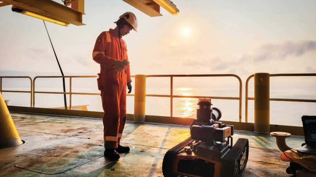
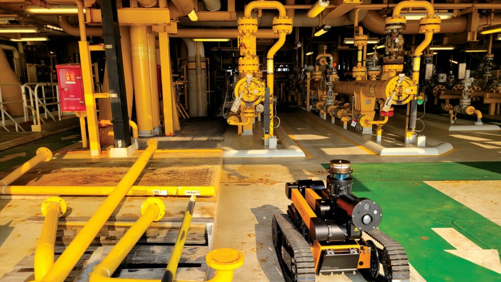
While a very minimal number of companies has managed to ATEX-certify its uncrewed systems, Austria-based Taurob is among the leaders. Its flagship Inspector product is now in use among initial customers in the oil and gas sector, particularly in relation to the kinds of largely uncrewed, unpopulated offshore platforms that must be routinely inspected for faults and leaks, either by helicopter crews using time, fuel and money to fly out and assess first-hand – or by resident, self-recharging, ATEX-certified autonomous robots.
The company’s founders began in 2010 with the Taurob Tracker; a robot built principally to help firefighters (and also used by the Austrian military), which Taurob claimed as the first market-ready ATEX-certified robot, establishing an early niche for the two co-founders and their team in ATEX (although not fully autonomous) work.
“But it wasn’t until TotalEnergies started its Argos [Autonomous Robot for Gas and Oil Sites] Challenge in 2014 to 2017 – where we won against many other competing robotics companies – that we were awarded the r&d challenge, which eventually birthed the Taurob Inspector in 2020,” recounts Jorge Regueiro, VP for r&d hardware at Taurob.
“But while Total was very happy with the two first prototypes we gave them – and which started working in its facilities that year – it was such a complex first product design, and we ourselves saw so many problems we wanted to fix and keep improving upon.”
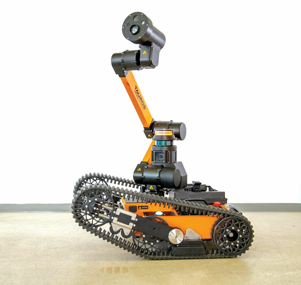
Hence, a busy journey of improvements followed, with those gradually giving way to smaller optimisations that continue in minute forms today on the 80 kg Inspector. As well as being ATEX-certified, the 75 cm tall robot is IP67-rated, handles -20 C to +60 C temperatures, and inspects largely using a sensor head atop a robotic arm that can extend to 1640 mm above the ground.
In addition to that sensor head’s various measurement tools, Inspector is equipped with a plethora of other sensors, as well as computers and novel mechanical innovations enabling it to autonomously traverse throughout industrial environments without needing help or special accessibility infrastructure, its two electromotorised tracks handling stairs unhaphazardly. So long as 4G or wi-fi are present for comms and monitoring, 85-264 V AC (47–63 Hz, 3.3 A at 230 V) outlets are offered for recharging and standard nitrogen supply systems are installed, Inspector is certified to start working on-site.
“But learning never stops; today, we’re still engaged in continuous testing, trialling new sensors and attempting to unearth hidden problems before they can present in the field,” Reguiero says. “We take reliability very seriously and are aiming to eventually make the product maintenance-free, while also targeting several other improvements to make Inspector a really consistent and trustworthy system, even in really dangerous environments.”
Development history
Among the most important changes between the Tracker and the early Inspector occupying Taurob’s work from 2017 to 2020 was a switch from worm gears to harmonic drives for the mechanical joints. Use of worm gears had meant some mechanical play or backlash would occur, but by that time, play-free harmonic gears became more widely available.
“We also worked to give the robot a more industrial look, with a big housing redesign, and we changed some safety-related structures in proprietary ways for ATEX compliance; generally, at that time, however, the traction system didn’t change too much and most other subsystems stayed the same – but not for long,” Regueiro muses.
Taurob’s biggest gripe with its first prototype was the robot arm’s cabling. At the time, harmonic gears could not run on hollow shafts for running cabling, nor could their motor configurations; hence, the cables ran outside of the drives in metal-reinforced protective tubing.
“But because of the arm’s joints’ movements, getting the tubes’ kinematics right was quite hard; some of the joints needed to move almost 360°, so the tubes just couldn’t offer enough slack, and they could get entangled or pulled too hard,” Regueiro recalls.
“So, a lot of effort first went into developing the arm’s joints so that they could successfully run the cables internally. Afterwards, our next big milestone was probably a collection of sealing improvements – on the first prototypes, sealing was installed very manually about the body and it wasn’t airtight like it is today, so we worked a lot on that.”
And naturally, design-for-manufacture went from being a far-off thought in Taurob’s early r&d phases – particularly compared with functionality, reliability and ATEX-compliance – to being a vital consideration in the early 2020s. That encompassed many small, practical improvements on Taurob’s part, such as making certain screw inserts more accessible, defining certain elements or their positions more clearly, and even adopting and implementing the Japanese ‘Poka-yoke’ concept of mistake-proofing assembly processes and tools for the sake of lean manufacturing.
“Poka-yoke, when done correctly, makes processes foolproof such that parts cannot be installed incorrectly; they can only be installed in the one, correct, way,” Regueiro explains.
A few other large changes followed these earlier evolutions. The powertrain, for instance, would gradually incorporate a new, more intelligent and long-lasting set of traction treads, as well as a safer, more energy-dense battery.
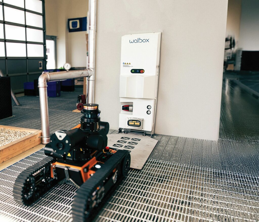
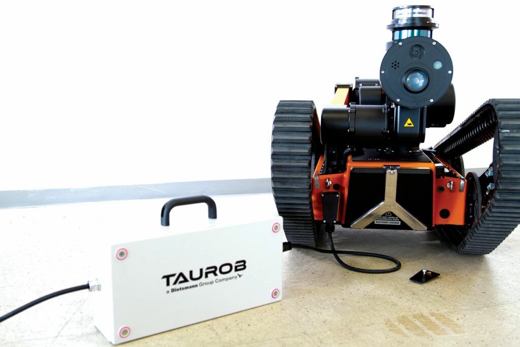
More importantly, however, that powertrain required manual plug-in charging. Hence, Taurob started work on its Wallbox stationary docking and recharging station. The prior, first-generation system, named ‘Docking Station’, was a larger system than the company was happy with, standing roughly 3 m by 2.5 m by 2 m, housing a protective atmosphere for explosion prevention.
To reduce bulkiness and price, three years of r&d went into making Wallbox smaller and cheaper to manufacture, as well as making it ATEX-certified, so that Taurob’s robots can drive onto it within explosive atmospheres. The system also enables the robots to recharge from empty to full over a 100 minute rest.
The Wallbox features a 1406 mm tall and 688 mm wide electronics unit, with a drive-on floor plate that extends the system 1372 mm from the wall. Integrated into the unit is a docking interface, a sealed conductive power supply, pressure gauges, an emergency stop button and an input thread for nitrogen to pressurise (or manually purge) the robot before it commences operations.
With the robot and its infrastructure largely optimised, Taurob can now construct up to 50 units per year, and has produced 50–60 so far, with capacities to be increased if demand growth for the very niche, high-end system should make the current capacity insufficient.
Robot architecture
The majority of Inspector’s 80 kg weight is distributed across its body and tracks close to the ground, guaranteeing that the robotic arm’s movements of the inspection head impart no significant movements on the CoG.
The body is a largely cube-shaped enclosure, sealed to IP67, including when the battery is eventually swapped (for long-term replacements, rather than as a speedier, yet more manual alternative to the automated charging) in and out of its compartment in the body’s front. The two tracks change their shape through a form of variable transmission (detailed later in this feature), between a rectangular shape for support or traction on inclined surfaces, to a triangular shape for tackling both stairs and flat terrain (as this shape reduces the ground footprint and, hence, friction).
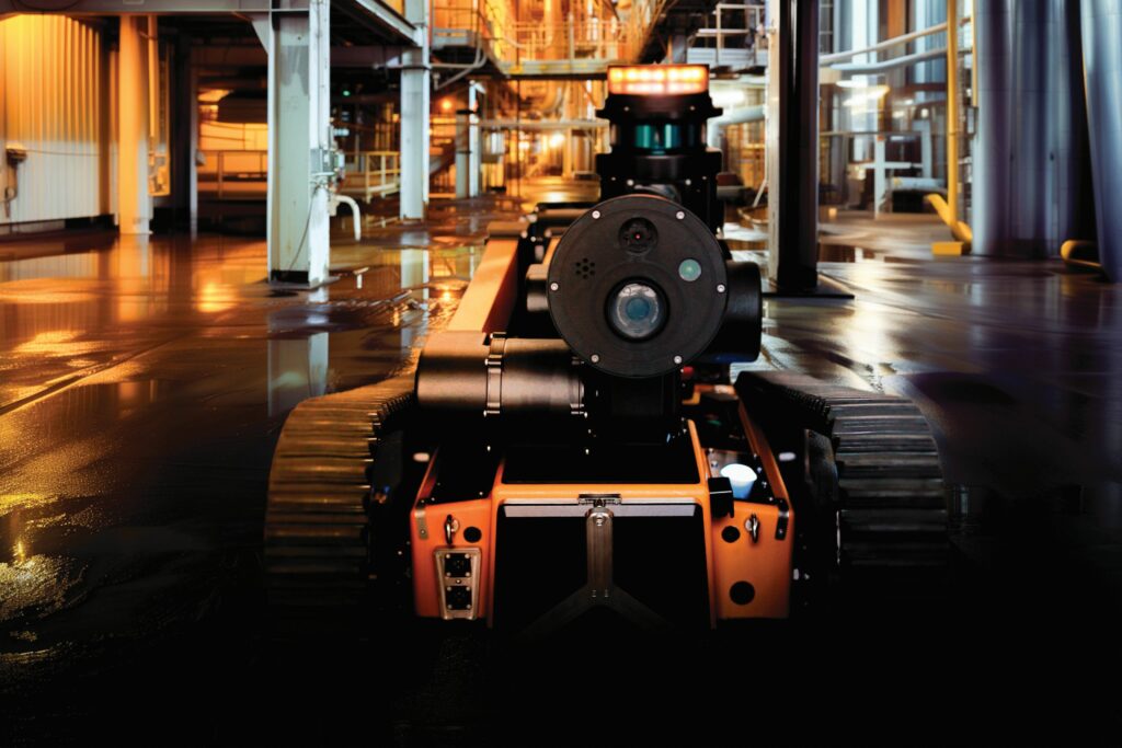
Two sets of subsystems mount atop the body. At the rear, Taurob installs a multi-gas sensor and Inspector’s radios and antennas. Nearer the front-left is a rotating structure, upon which are – from bottom to top – the first of the robotic arm’s tilting joints, a 360° mast of four cameras, a 3D Lidar and a warning light to indicate whether it is safe to approach.
Two more servo joints, for tilting the arm’s upper half and the inspection head, respectively, are found as one continues up the arm. The two arm members contain no subsystems other than cabling and the aforementioned servos; the upper half measures roughly twice the length of the lower. The inspection head meanwhile integrates a 4K camera, a 20X optical zoom camera and an IR camera, as well as a directional microphone for tracking audial anomalies (with optical gas imaging cameras available as an option soon).
Airtight house
The body’s enclosure and primary structural element is a carbon composite box, with that material being chosen partially for its great strength-to-weight ratio, and partially for the ease with which carbon can be delivered as a single piece formed with multiple functional features, such as mounting tabs, apertures and fastener holes (rather than needing to attach or cut these afterwards), depending on how it is laid up and cured.
However, aluminium’s higher capacities for absorbing forces and flexing under pressure are the reasons why an additional aluminium floor plate is installed as reinforcement to the bottom of the carbon enclosure; Regueiro notes that carbon alone is not an optimal material for taking or distributing loads in the shear axis, or elsewhere outside of the direction in which its fibres run. Hence, Taurob’s engineers principally mount any subsystems likely to impart shear forces to the floor plate, instead of to the carbon housing.
“The arm, meanwhile, is quite simple. We essentially just join the three pitching servos and the lowermost rotational servo with some very standard carbon elements, so structurally it doesn’t need special or complex considerations as the body does, aside from some weight reduction work on the joints and arm elements to minimise the arm’s torque requirements and power consumption,” Regueiro continues.
“There’re a few subsystems in the body that route their stresses through both the housing and floor plate. It’s very tightly integrated at the moment and we’re considering a more modular approach in the future, but ATEX requirements mean that that’s not so easy.
“Frankly, getting the IP67-rating is really easy. To be ATEX-rated, the carbon body needs to be airtight: inside, there’s a pressurised body of inert nitrogen gas, and that needs to stay stable even with moving parts like motors and actuators in it. So, everything inside and in the walls of the body has to be super tight; it has to hold pressure precisely throughout its operating time, from the moment it leaves the Wallbox until it returns, which can run from four hours as standard up to seven hours at a stretch.”
While carbon fibre might strike one as a potential sparking risk in explosive atmospheres if the material suffers a crack or break, Taurob coats every inch of the carbon in a protective paint, per ATEX requirements specifying that a compliant system’s housing material must be conductive, and must also adhere to a maximum surface resistivity. The paint fulfils the latter property, Regueiro noting that finding a suitable protective paint supplier was extremely difficult; less importantly, the paint also yields an aesthetically satisfactory orange finish.
Going forwards, Taurob plans some further structural optimisations in thermal management terms, particularly about the cameras to maximise the thermal stability around their locations, and hence optimise their inspection results.
“Our robot is specified from -20 to +60 C, and -20 C isn’t so much of a challenge since most subsystems generate their own heat, and that heat gets concentrated nicely inside the robot – but blast temperatures can be a real danger,” Regueiro says. “So, we simulate all new developments inside a test oven over lengthy periods at 60 C, and we optimise new designs to have good thermal coupling with the housing, along with adding fins and ribs where convection exchange might be otherwise insufficient. We’ve made huge strides in thermal management these past few years and really solid gains by investing engineering hours into that.”
Battery
The aforementioned changes to Inspector’s battery over its development also prioritised ATEX compliance, with the biggest shift being a switch from nickel metal hydride (NiMH) cells to lithium cells. NiMH as a chemistry was sufficiently explosion-proof for ATEX certification, but in 2024, Taurob introduced a new, 15 Ah, lithium-based pack that took Inspector’s maximum recharging time down from 11 hours to 90 minutes.
“NiMH also limited Inspector to two hours’ endurance, so you can see how well lithium improved our uptime-to-downtime ratio,” Regueiro says.
“ATEX regulations put strict limitations on cell selections; they require extensively tested and analysed cells, and specify close guidelines on what kinds of cell connections are allowed. Luckily, new lithium cell technologies are very electrically, thermally and chemically stable, and we’ve just had to work to find a supplier that could give us physically large cells, as stringing many small cells together wouldn’t enable the very tight BMS control and balancing that ATEX demands.”
The battery was co-designed with a partner specialising in BMS engineering and cell supply networks, Taurob providing critical ATEX context for subsystems such as the cell-to-cell connection boards, short circuit protection systems and housings, together producing the safest pack conceivable by either company.
It was then validated through ATEX testing, which was largely performed in-house, with persistent support from an ATEX-notified body who could confirm and sign-off on the pack’s compliance.

“There’s some crazy tests in there, too; in one of them, the battery housing had to be stored in a thermal chamber for a month, at over 90 C and very high humidity, after which it was taken down and tested for sufficient remaining sturdiness,” Regueiro recounts.
Intelligent traction
Two 300 W BLDC motors run inside the machine, each directly driving a traction wheel that powers its respective track. Having two separate motors ensures that the tracks can move independently, allowing tank steering and turning radii controllable down to zero.
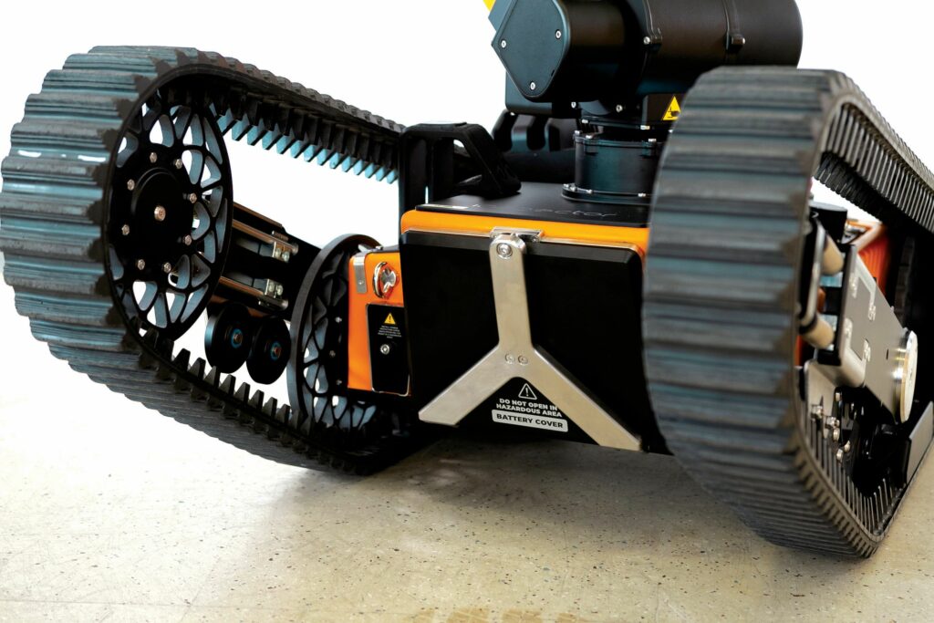
Additionally, the tracks’ changeable geometry comes from their arrangements of wheels and flippers. Each track is largely driven by two wheels: the traction wheel and a driven wheel, the latter ensuring a minimum length of track is pressed flat against the ground.
A flipper is installed between, from which a third, tensioner wheel extends further forwards of the driving and driven wheels, to press into the track and define its shape. When the flipper is electromechanically actuated to point upwards, the track’s forwardmost point lifts up to form a scalene triangle; when it points downwards, the track forms a rounded rectangle or ‘stadium’ shape.
“That helps us climb stairs and overcome obstacles; other UGVs and robots integrate at least one extra pair of tracks, or just function by walking with legs, both of which are much more expensive than our patented geometry-shifting approach,” Regueiro says.
“We can also adjust the track geometry as we climb up and over each step of a staircase, maximising grip and tension against each surface for maximum climbing security, and it works very similarly when climbing down also.”
Several smaller wheels are also integrated in each track to provide further contact, tension and bracing points for the tracks in unusual or irregular traction scenarios, and thereby eliminate as many ways as possible that the tracks might be lost (a perennial concern for operators of tracked machines).
As well as this shifting mechanism, Taurob made sure that its tracks are designed in a proprietary manner, involving charging them with an anti-static device to ensure it is conductive.
“Conventional rubber tracks build up immense static electricity through their friction with various surfaces, potentially risking an explosion; plus, the grated, non-slip metal floors common to industrial installations caused some of our earliest track designs to disintegrate, falling apart before long,” Regueiro recounts.
“It took us almost two years to develop a track which could be cast as one piece, functioning as a tyre and holding integrity for the lifetime of the robot, as well as fulfilling ATEX anti-static requirements. We went from issuing three pairs of tracks with each robot, to just delivering each unit with the tracks it has on.”
Autonomy
The robot’s knowledge of where track shifts are needed comes from a pre-programmed input of navigation data, its IMU and other sensor data identifying positions or phases in its inspection routes where it needs to adjust the flippers’ gradients for an expected climbing gradient.
As much as industrial customers can provide accurate digital twins of their facilities, Taurob will in most cases insist upon a first-time, ‘recognition phase’ drive, in which Inspector is piloted remotely around its inspection routes, and uses its 3D Lidar to generate a point cloud for use as a localisation reference map, including recognitions of stairs, pipes and other noteworthy features.
“We did have one customer whose digital twin was so great that they integrated Inspector and did virtual test drives in their simulation software, all on their own – it was really impressive – but generally, this first trial is useful for the Lidar to recognise where the robot is, and to notice unexpected obstacles so that it can calculate alternate paths to its next waypoint.”
While a low-duty IMU has been sufficient alongside the sophisticated Lidar-based localisation so far, Taurob is actively looking into higher-end alternatives to enhance trust, redundancy and precision in its navigation architecture.
Algorithmic processing for navigation, traction control and inspection work (including communication of inspection data to the end-user’s cloud or on-site servers) is executed by a ROS-programmed industrial PC, chosen for its very effective thermal management – the temperature requirements having limited which computers Taurob could use – although expanding options in this regard mean that the company is switching to a new model and supplier in 2026.
A second, lower-duty, certified PLD controller runs periodic safety checks to ATEX standards across Inspector’s machinery, and will trigger a shutdown if anything measures short of ATEX requirements.
“We’d also like to integrate a proper AI computer with GPUs for camera-based feature recognitions or inspection analytics. We’ve not been able to do that owing to insufficient thermal management or maturity in the products available just yet; but in the future, it’s very much on the cards,” Regueiro says.
Robot arm
Much like the traction system, the inspection arm’s control is also governed and automated based on pre-programming: either through a ‘recognition phase’ or a virtual simulation, the robot is trained to recognise and store – based on recorded memory of how its operator manually or virtually operates it in this first trial mission – key waypoints where it must stop to inspect industrial assets.
Those include commands as to the correct height and angle with which the inspection head must be posed, and how far the head’s optical zoom camera must zero-in. The pose of the head combines exact positions for the lowermost (pan) rotary actuator and the three upper (tilt) actuators, and naturally any combinations of the four sensors within (or the other sensors inside the mast containing the pan actuator) may be autonomously triggered.
“Naturally, the bottom joint has a bigger turning radius than the other three, and so it works more continuously than the others, meaning it is usually the first of our actuators to reach end-of-life and need replacement,” Regueiro says.
“Funnily enough, back when we had the NiMH battery, that joint had a life expectancy of 10 years, but with our lithium battery, our customers could use Inspector maybe 10 times more often than they used to, either charging or moving maybe 24/7, as our own test units do in our trial arena. That means the pan joint can reach end-of-life after a little over a year of continuous, highly-intense operations.
“But it doesn’t affect maintenance intervals because ATEX regulations demand that we perform yearly maintenance anyway. So, whenever a customer’s Inspector comes in for that, we check the logs to see how many movement cycles the arm and its joints performed, and we can determine if a servo, a cable or anything else in the arm merits replacement.”
Inspection
Developing the inspection head and the lower sensor mast required selections of heavily size-optimised devices to make best use of the limited dimensions to which Inspector had to adhere (to avoid being overlarge for navigating industrial spaces).
“It was also important for us to use Ethernet cameras instead of USB cameras, which would need an added nearby computer to convert the data into Ethernet for better speed and bandwidth,” Regueiro says.
“FoV was also important, especially for the 360° camera mast: each camera needed just over 90° horizontal FoV to ensure an overlap that would guarantee constant 360° visibility. Resolution is, naturally, important too for making valuable visual and thermal data, and good temperature tolerance probably goes without saying – there’re many cameras on the market that can tolerate 45 C, but not so many that can make 60 C work.”
Temperature was also important for the Lidar, as was its effective depth or range; the 20 cm effective limit of older small Lidars would not suffice for Taurob’s wish to autonomously localise in wide corridors and hallways as precisely as in narrow ones.
Optimising navigation references also merited high point densities and its vertical FoV to respectively define objects and capture decent views of the ground around the robot.
“We also avoided Lidars that depended on automotive Ethernet because we use standard Ethernet and couldn’t integrate a junction box for interpreting or translating the former,” Regueiro adds.
Remote monitoring
For persistent comms, one radio and SIM card integrated with the industrial PC provides LTE connectivity, while two wi-fi modules (one for transmit and one for receive) enable direct networking with the customer’s facility.
“But connectivity with an ATEX robot is very different from onboard, say, a defence UGV; the amount of output power that these modules can emit is very tightly limited owing to certain gases presenting ignition risks depending on the EM radiation levels from radios and antennas,” Regueiro notes.
In addition to limiting the combined output power from the radios and antennas to 2 W, impact tolerance was another crucial antenna requirement.
“ATEX regulations require that you go in assuming a 1 kg mass will at some point fall from a height of 0.7 m onto any part of your robot – and the robot must remain airtight after that,” Regueiro explains.
“So, the whole housing must be built really sturdy: not a nice restriction for an antenna. You can’t just protect it in metal because then you’ll have made a Faraday cage; you need materials that are strong, flexible and still RF-transparent. Some off-the-shelf antennas come certified as sturdy enough to survive ATEX impact tests, but when we’re having to use antennas that aren’t, there’re some flexible, hard plastics that function well as radomes.”
When it comes to visualising and assessing the data from Inspector – both inspection measurements and operational telemetry – Taurob keeps an open, flexible approach in software terms. While hardware choices are limited to ATEX-certified tablets and PCs (regardless of whether Taurob provides them or the customer picks their own), Taurob supplies either software- or web-based versions of its control interface.
Additionally, various customers and partners have worked to integrate Taurob’s software with their own to enable mission planning and monitoring for Inspector units through their known, familiar UIs, with Energy Robotics and Yokogawa being among the companies to do so.
Future
Although well established in the oil and gas sector, Taurob is actively researching and working to expand into other industrial markets, as well as continuing internal r&d to realise its dream of a 10 year maintenance interval; its engineers tackling each component with a lifespan shorter than 10 years one at a time.
“We’re also always looking for new, valued sensors to integrate for the industrial inspection space; it’s now public knowledge that we’re upgrading Inspector with Sorama’s gas detection sensor technology, and we’ll have an ATEX version by the beginning of 2026,” Regueiro says.
Key specifications
Dimensions: 1070 x 720 x 600 mm
Weight: 85 kg
Operating speed: 0.5 m/s
Maximum arm height: 1640 mm
Nominal endurance: 240 mins
Maximum charging time: 90 mins (20–80% in 45 mins)
Maximum traction incline: 45°
Operating temperature range:-20 to + 60 C
Some key suppliers
Industrial gas detectors: Dräger
Thermal imagers: Teledyne FLIR
Acoustic sound cameras: Sorama
Data links: Rajant
Integration services: Rockwell Automation
Integration services: Kalypso
Integration services: Energy Robotics
Integration services: Yokogawa
UPCOMING EVENTS


