


Suter Industries
Running the redline
Rory Jackson visits this Swiss company at its headquarters to learn how it is building a new wave of spark-ignited, boxer, twin two-strokes for the UAV space
(All images courtesy of Suter except where stated otherwise)
With regulations in the EU aimed at curbing and eventually eliminating internal combustion engines in road vehicles, the future of European engines – and particularly the expertise and innovative capacity around them – is likely to lie not amidst the automotive industry but in the UAV industry.
Two-strokes’ high power density make them ideal in the many military and commercial applications increasingly trusted to uncrewed aircraft. Moreover, the performance demands of customers in areas such as surveillance, rescue, reconnaissance and heavy industry has spurred huge advancements in their fuel efficiency, lifespan and vibration reduction.
Hence, it is largely because of UAVs that there exists a range of small, high-quality two-strokes (outside of motorsport-type bikes) today, designed for running close to redline power for at least eight or nine hours, non-stop and at high altitude, without faults or failures.

The Switzerland-based corporation of Suter Industries AG and CAE GmbH has been a particular success story in such engines since our last feature on them in 2020 (Issue 32).
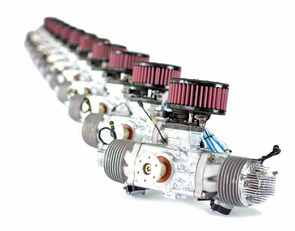
Some key areas of Suter’s technology and capabilities have changed dramatically from those we reported five years ago. Most glaringly, there are now four separate products making a family of Suter Industries engines, where only one existed in 2020, with all four being spark-ignited, boxer, twin two-strokes.
The first engine, the TOA 288, is now well known and established in the wider UAV industry, being used as the power unit by successful UAV companies such as Dufour Aerospace (Issue 52) and Volansi (Issue 33). It is, as readers may recall, an air-cooled engine, weighing 8.9 kg and outputting 23.9 bhp (17.6 kW) at 6500 rpm – though in the six years since its launch, its TBO has been revised upwards through optimisations and endurance testing, from 250 hours to 500.
Since productionising that engine, Suter has created the TOW 288, a water-cooled version of the TOA 288, slightly heavier than its air-cooled predecessor at 10 kg, but producing 20 kW (27.2 hp) and 29.2 Nm at 6500 rpm, making it the higher power and torque solution.
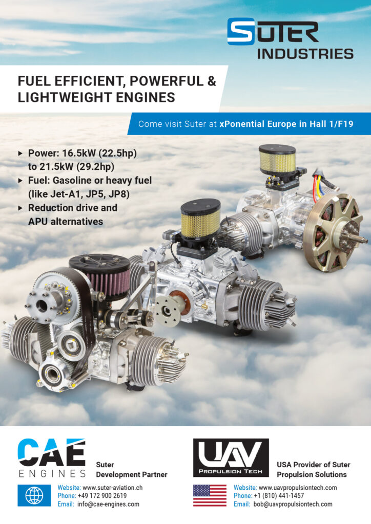
In an even bigger leap (in terms of the engineering undertaken), the company then created the HF TOA 288-SDI, an 8.6 kg, heavy fuel engine, based on the TOA 288 platform and still air-cooled. This engine runs on Jet-A1 as standard, with JP-5 and JP-8 also compatible, with a maximum power output of 16.5 kW (22.5 hp) at a crank speed of 6750 rpm and a peak torque output of 24 Nm at 6000 rpm.
Most recently, Suter has unveiled the TOA 330 as its largest engine, developed with a 330 cc displacement instead of 288 cc to satisfy inevitable customer requests for increased power, although this system is otherwise air-cooled and 95RON gasoline-powered (with options for 91MON Mogas or LL100 Avgas), like the TOA and TOW 288.
Additionally, each engine operates with a service ceiling of 6100 m (and can be cold-restarted), is digitally managed via a 12 V ECU and lubricated with two-stroke oil API TC, which burns up via combustion.
However, it is promised that Suter’s portfolio will continue growing to suit the widening range of UAVs and other light aircraft being designed today, the company disclosing to us that a heavy fuel version of the TOA 330 – a HF TOA 330-SDI – is in the works. That project has not gone into production yet, and cannot be revealed in detail, but it will be once validated and made certifiable through testing.
As well as having the same service ceilings (tested up to 9000 m), all four engines are spark-ignited with capacitive discharge ignition systems and EFI, controlled by an ECU that manages based on an Alpha-N strategy. That focuses on adjusting crank speed, according to throttle position and air flow (governed via a Volz DA 15-N, a servo prized by Suter for its precision, reliability and longevity), but also compensates for readings on exhaust gas temperature, cylinder-head temperature (CHT) and other readings.
In addition to this fourfold expansion of its aviation engine offerings, a similar scale of change has happened at Suter Industries itself since our last investigation. While long known for its engineering services across different categories and seasons of motorsport (see boxout), the relative stability and steady growth of the UAV industry has motivated the Swiss company to invest heavily in production and testing systems principally for its aviation engines.
Now an established engine manufacturer with multiple, long-term UAV OEM customers, Suter invited us to visit its facilities in Turbenthal to see firsthand how it has organised its production processes and machinery to meet the growing needs of the uncrewed aviation industry, and the ways in which its engine portfolio has evolved to power UAVs to new heights.
Suter: company history and activities
Suter Industries was originally founded in 1996, as Suter Racing Products, by former Grand Prix motorcycle roadracer Eskil Suter and his brother, Simon. It went on to rebrand as Suter Industries in 2017, to better reflect its mix of activities across motorsport, aviation, and electric and hybrid powertrain technologies.
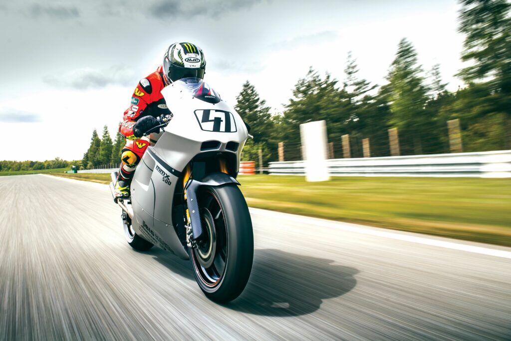
In the decade following its foundation, Suter cut its teeth on several high-profile projects across motorcycle racing, including the design and build of the engine for the Petronas FP1 in the Superbike world championship in 2002, the Kawasaki MotoGP motorcycle in 2004 and the Ilmor X3 MotoGP motorcycle in 2006. The company has also partnered the motorsport teams of BMW and Mahindra, and it most notably won the Moto2 World Constructors’ Championship in 2010, 2011 and 2012 with the Suter MMX-2 motorcycle.
In 2010, the company commenced design and development of a new engine for aviation, optimising its power-to-weight and power-to-volume ratios, gradually also tackling its TBO and fuel efficiency, among other key parameters. It went on to officially launch and productionise its first aviation engine product, the TOA 288, in 2019.
As indicated, Suter also contributes significant r&d into advanced clean powertrain technologies, productionising an aircraft APU in 2017. The company quotes having achieved 16% reductions in fuel consumption across projects centred around hybridising ICEs, and it continues to be involved in cutting-edge research of such powertrains today, including one focused on hydrogen-powered aircraft development with ETH Zurich.
Manufacturing and QC
A careful selection of components has enabled Suter to commit to stock from long-term suppliers. For instance, across all four engines (and others in development), the company uses the same number and selection of high-end titanium bolts, which it lauds for being machined into pieces with consistent tolerances and light weight.
Additionally, since our previous feature, the Swiss company has moved away from safety wire and towards aviation-certified safety cable, the latter being far easier to handle in terms of user-friendliness, intuitiveness and time-savings.
On the subject of supply, Dietrich Kehe, CEO of Suter Aviation, adds: “One key feature now of our ECU system is that no electronic components out of China or Taiwan are used.
Not to be pessimistic, but if you saw what happened to global supply lines during COVID, you should know it’s only a matter of time before supply chains stretching halfway around the world get ruined again. It makes it harder to source electronics, for sure, but there are ways to make it work if you look hard enough.”
As of writing, Suter has two production facilities at its Turbenthal HQ, the second having been opened very recently to expand manufacturing and testing throughputs beyond those of the former (which has largely reached capacity), with some limited and proprietary elements of production already taking place at the new facility.
Entering the main facility, one finds two rooms populated by computers: a design room for simulations, including high-density CFD and FEM analysis, followed by a CNC machine programming room. Engineers in the former principally feed parts for new projects and new iterations of existing components into the latter, from which the CNC engineers write instructions for the metal-cutting machines to execute.
As the company produces engines intended for high-end, certifiable uncrewed aircraft, made by engineers with stringent and changeable requirements, flexibility is key to Suter’s production process. Hence, it has very deliberately optimised everything around CNC machining and very little around casting.
In Suter’s view, casting would also mean further disadvantages, compared with CNC machining, such as having to make the parts thicker and less lightweight than they are at present, as well as having to X-ray or otherwise inspect cast components deeply to confirm the absence of porosities, and of the sorts of flaws or weaknesses that can occur as a casting mould ages and wears.
“But if you buy billet for machine cutting, you know it’s going to arrive as perfectly solid metal with no voids or micro cracks that could make it into the final engine,” says Lars Jaeger, CCO at Suter.
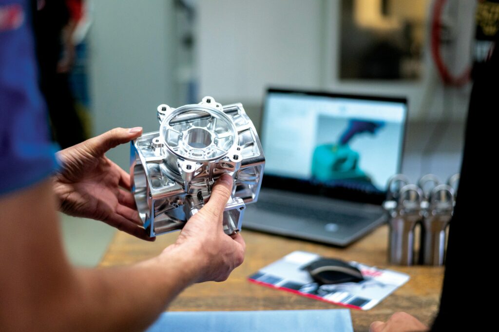
“If a customer were to ask for 10,000 or maybe 5000 units, and sign a contract saying they’ll never ever request a design change, then maybe we’d consider casting. But we’d have to re-evaluate the whole production process from start to finish. If you look, for instance, at the walls of our crankcase [including the cylinders, which are integral to the crankcase], you’ll notice they’re just a few millimetres thick in most places, saving a lot of weight.
“That’s really hard to pull off unless you’ve amassed a lot of in-house expertise and training on how to use CNC machines really well. We wouldn’t have survived in motorsport if we hadn’t; the race is always on Sunday. If a part needs to be replaced or redesigned, it has to be done so perfectly, and there’s no time to lose.”
(Image courtesy of the author)
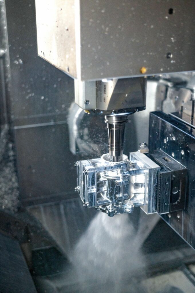
Within the production area, numerous five-axis CNC machines can be found; these being indispensable to the geometries required of the crankcase and cylinder head. Some three-axis CNC machines are also present (and used for relatively less complex parts, such as crankshaft pieces and connecting rods), as are automatic dual-spindle lathes and a TIG welding robot.
The CNC machines are run for most of every business day, with shifts from early morning late into the night, as part of a strategy built around flexibility. Custom requests or new flight-testing data received one morning can result in newly iterated parts being cut before the next.
“We also have our own engraving machine, which is important as every single part used in each aviation engine has to be engraved with a serial number. That’s critical for 100% quality control [QC], and hence traceability and certifiability of what we supply to UAV makers,” Jaeger adds.

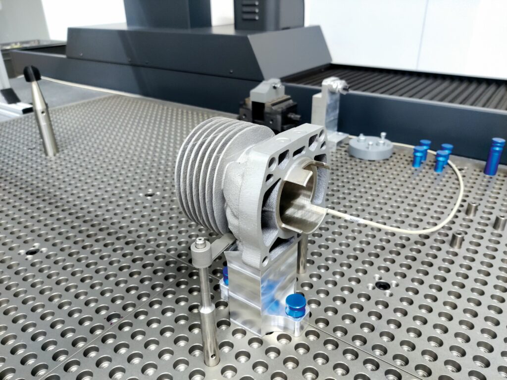
“In the interest of QC and reaction time, we decided two years ago to invest in a 3D coordinate-measuring machine [CMM]. Naturally, controlling and validating the tolerances and geometries of every engine component is important. In the past we’d outsource the coordinate measuring, but that took too much time due to having to request the service, book a timeslot for the CMM, and transport our parts back and forth. Our validation times are much faster now.”
Testing
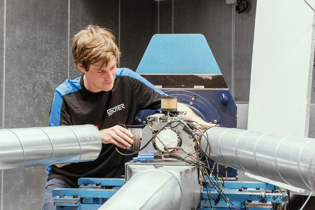
Four propeller dynamometer cells populate Suter’s basement testing facility. Stepping into the first cell, where the firm previously performed a 1000-hour endurance test of the TOA 288, one finds (surrounding the dyno) a 400 kW brake, a HVAC system for controlling cell temperature and pressure, an in-house-developed power-generation system, and a motorbike speed tester on the ground (so the racing projects and aviation business can profit from the cell).
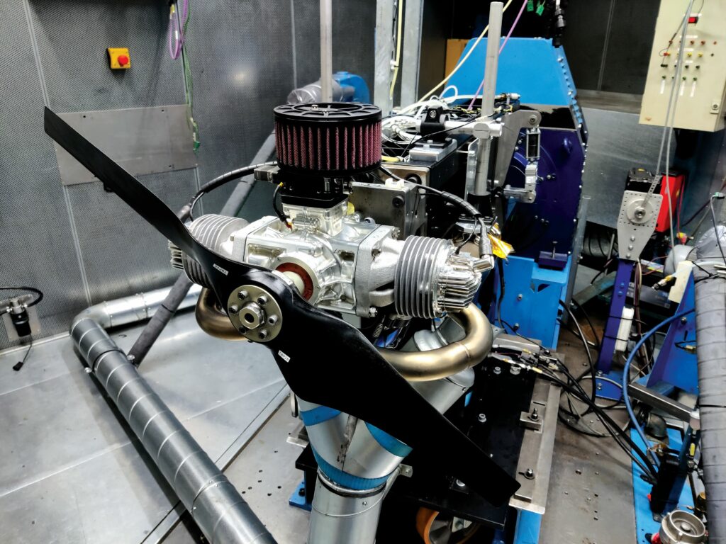
(Image courtesy of the author)
Some minor variations exist between the cells, depending on specific testing applications. One dedicated to testing the HF TOA 288-SDI, for instance, is designed to deal appropriately with the emissions from burning kerosenes.
All, however, serve to perform break-ins (including the initial wear needed to mate each piston ring to its cylinder) and final testing on every unit coming from the manufacturing rooms upstairs, and also to analyse new engine designs and improvements, including any new calibrations of the ECU (a multi-core system supplied by an undisclosed partner in Italy).
As Alessandro Giussani, CTO at Suter, explains: “The engine brakes we use are classical eddy current brakes, which let you test the engine in a wide range of rpm and throttle combinations. Once we get the basic calibrations from those, we can then move the engine onto the propeller dyno to fine-tune those calibrations for specific propellers.
“The heavy fuel-testing cell incorporates a carbon ventilation and filtering system for health and safety compliance, and a special cooling arrangement of blowers pointed to the exhaust system, to compensate for the fact that it is running statically and not on a moving aircraft. But, aside from those two factors, there’s no drawback to running heavy fuel engines in our dyno cells.”
The cooling system is vital for simulated thermal management, as the air drawn by the propeller is insufficient to recreate airborne cooling conditions. Additionally, the ventilation system often keeps the cell’s air pressure slightly lower than ambient, not only helping to simulate altitude conditions but also preventing harmful gases from ‘wanting’ to escape outside the cell, potentially to where the test engineers sit.
As well as measuring all output parameters for engine performance, including fuel consumption, the sensor arrangements in the test cells typically also track the pressures and temperatures found in the cylinder, crankcase and oiling system used in the heavy fuel engine (discussed later).
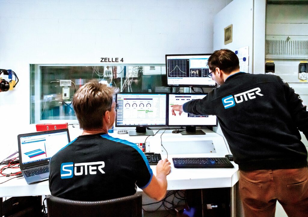
In addition to watching the engines through windows, the testing engineers monitor four to five computer displays per cell, each featuring a software interface covering a different task. One tracks standard engine operating parameters, including CHTs, exhaust gas temperatures, manifold air pressures, and so on.
The second monitor shows the test profile under way, and how far an ongoing test may have progressed through the overall duration (enabling parameters to be tracked and compared over time). The third displays the ECU’s engine-management software, thereby tracking component functionality and engine inputs, as well as empowering real-time calibration work.
“The fourth screen isn’t always activated, but it typically shows our combustion analyser. Mainly during development, we’ll instrument an engine with some special pressure sensors in the combustion chamber to gauge pressure at every 0.1° of crank rotation, giving 3600 points of pressure per cylinder per rotation,” Giussani says.
“All this data helps generate performance indexes of each engine – particularly at the start of combustion, mid-combustion, end of combustion, on combustion pressure and fluctuations thereof, knock behaviour – to understand how best to minimise losses and unwanted behaviour.”
Additional monitors can be used for various tools such as fuel ancillary analysers, battery testing software and electric motor analysers for hybrid powertrains, with Suter’s test equipment portfolio including two battery simulators, one capable of outputting up to 100 kW at 1000 V, and the other capable of 250 kW.
Since it began operating, Suter has consistently partnered with Kristl, Seibt & Co Gesellschaft (K&S) in Graz, Austria for all of its testing machinery and tools, including the design, manufacturing and configuration of all its dynamometers.
“When it comes to something like testing equipment where precision in everything is absolutely vital, then it’s equally important to work with a partner who has a similar size, agility and culture to yours,” Giussani says.

“We don’t make the kinds of engines that have existed for 100 years; we work in motorsport and uncrewed aviation, where you have to push the envelope to keep your customers. That means we’re often testing our engines to lengths or parameters that are beyond what has been done or at least documented before, which triggers unpredictable outcomes. So we need testing cells and equipment able to handle and measure that sort of thing, K&S’s dynos and sensors have always done so well.”
From air to water
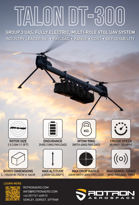
Development of the water-cooled TOW 288 was pursued to fulfil integration cases in which the engine load runs independently of air-cooling performance (when coming directly from airspeed and propeller speed). Specifically, Suter had been asked for a version of the TOA 288 suitable for powering a helicopter.
Traditionally, various factors prevent helicopter prop-blade downwash from sufficiently cooling the engine. For instance, helicopter engines tend to either have a shroud or fairing that blocks direct air flow from the rotor above (and in many UAV helicopter applications, the engine is installed where the cockpit of a crewed helicopter would be located, making propeller-derived cooling impossible).
Additionally, the use of a variable-pitch propeller to hover puts the engine at full load when there is zero forward movement through air, unlike in fixed-wing aircraft, which would typically move fast through air and thus be exposed to heavy cooling while at full load.
“To resolve that, one can either make a forced-air cooling system or make the full swap to a water-cooled version of one’s engine,” Kehe says.
“The former option is less complex in terms of the design and engineering steps needed, but we went with the latter, because in principle you can get significantly more power out of a water-cooled engine than an air-cooled one, and cooling with water-glycol makes your engine more thermally stable.
“Additionally, we’d studied many cases, including some six-cylinder helicopter engines where they used forced-air cooling, and we saw that the blowers necessary for sufficiently blasting the cylinder heads with air actually took quite a bit of power to function, compared with how those same engines were configured and run on fixed-wing aircraft. So, contrary to what you might expect, the forced-air approach is not always more power-efficient than liquid cooling.”
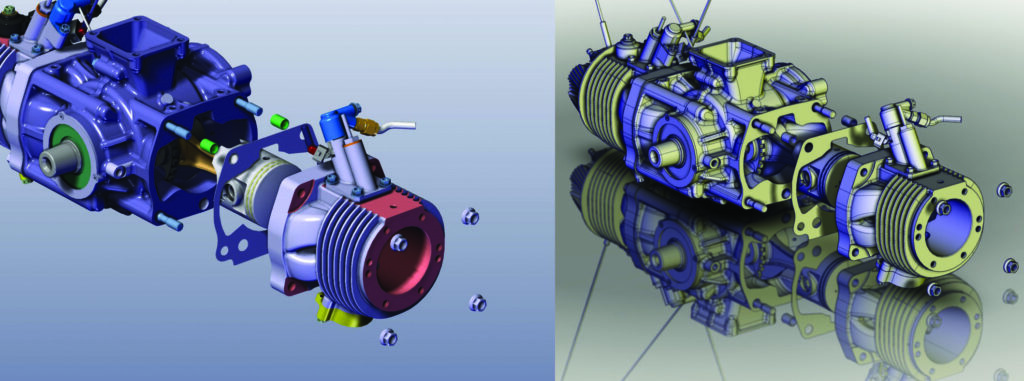
As indicated, the TOW 288 has the same combustion-chamber geometry and displacement as the TOA 288. Suter’s r&d for the liquid-cooled engine consisted largely of designing a water jacket around the cylinders, which took the place of the TOA’s aluminium fins.
The jacket design and flow paths are conventional, and uncomplicated by Kehe’s description. While a liquid-cooled four-stroke can be prone to hotspots without meticulous CFD to guide
high-velocity flow to sensitive points around the cylinder head (such as the narrows between the valves and spark plugs), the two-stroke is mechanically simpler, and hence it can be redesigned for water cooling relatively easily.
“We’d produced many water-cooled engines before, so we had lots of experience without needing direct inspiration from any one past project. We basically just designed an initial version of the jackets, optimised it in CFD software, and then built and validated prototypes, all within a few weeks. Most of the work was just making the prototypes,” Jäger says.
Suter also opted for an electrically-driven pump to drive the liquid coolant, rather than driving it mechanically (off a crankshaft gear, for instance); thus the ECU tracks the engine’s CHT sensor and directs the pump to increase or decrease flow velocity accordingly.

The end result of development here is an engine that is 1.1 kg heavier than the TOW 288 (stemming from the 500 g pump, and a slightly heavier exhaust, silencer and other parts), but producing an extra 2.4 kW (3.2 bhp) at 6500 rpm with the same 1 kW of electricity output from the alternator, and specific fuel consumption (SFC) improved to 306 g/kWh.
Sizing up
As Giussani explains, going from a 288 cc version of the engine to a 330 cc one was also generally straightforward. CAD versions of the TOW 288 were redesigned with an increased stroke in the cylinder and a lengthened con rod to match (as well as some very minimal adjustments to the length and geometries of the transfer ports). Prototypes of the 330 cc engine were then manufactured and tested, with the performance numbers largely matching those produced in computer simulations.
“There really were no major issues in producing the TOA 330. Far more difficult was making a version of the TOW 288 that could run on heavy fuel – our HF TOA 288-SDI,” Giussani says.
“The engine behaves very differently on heavy fuel due to factors like the HF TOA 288-SDI having to handle larger quantities of air and fuel despite running at similar speeds to the TOA 288. There were several similar sorts of issues, so optimising each parameter of the engine would have taken quite intense work and far more time than the project customer was happy with.
“In some aspects of heavy fuel engineering, we just made educated guesses to fix appropriate points and geometries, and move forwards into prototype testing. We may have left some points unoptimised, but we also consolidated the design in a very timely fashion, enabling us to start optimising some really important enabling technologies for heavy fuel operations.”
Semi-direct injection
Arguably, the most important revolved around how best to get heavy fuel into the cylinder with sufficient atomisation for a clean and uniform combustion.
“We all had great experience working with heavy fuel and direct injection [DI], so we evaluated different approaches to the problem of heavy fuel delivery in the 288’s form factor, eventually ending up with something called semi-direct injection [SDI],” Kehe says.
Suter’s SDI is achieved largely through positioning a fuel injector in the cylinder-head wall, pointed at a proprietary angle to the piston stroke, which then sprays more or less directly into the cylinder.

A variety of SDI systems have been used, with several notable examples among two-stroke snowmobile engines (some of which came from BRP Rotax, Ski-Doo and Polaris) to achieve reduced emissions, including approaches in which fuel was sprayed into the transfer ports.
“Semantically, DI means the fuel is injected into the cylinder from TDC. We looked into different approaches for this during our evaluation process, but the weight penalty of all of them was too high for a small engine like this,” Kehe says.
“DI takes high-pressure injection and so quite a bit of equipment to work, including a heat-protected injector, a high-pressure fuel pump and a powerful means for driving that pump, whether mechanical or electrical.
“Maybe one doesn’t notice all that weight as much on a big compression-ignition engine, but we determined it just couldn’t be the way forward on our two-cylinder spark-ignited engine. It would’ve also meant having injectors sticking out of the tops of our cylinder heads, which isn’t good for making a very compact UAV engine.”
The sideways-positioned injector and pump in the SDI approach are similar to those used in gasoline systems, although with a different injection pressure, but within the range for a conventional EFI.
As Suter claim, positioning the injector sideways relative to the stroke prevents the need for extremely high-pressure injection. In DI, fuel injects when the piston is closing on TDC, and pressure in the chamber is high.
But the placement and angle of Suter’s injector enables injection before pressure builds in the chamber (the piston then compressing the mixture), and protects the injector after combustion as the piston opens the exhaust port first, reducing heat impact and lowering cylinder pressure on the injector.
Additionally, a key issue with throttle body-injected heavy fuel is the spray can contact the wall before vaporising (or combusting), resulting in poor combustion and build-up of heavy fuel in the crankcase. Hence, SDI provides a more direct route for the spray to enter the combustion system allowing better mixture vaporization and combustion.
“During combustion, the piston is fired back down, exposing the injector to the cylinder interior again so it can spray. Then, the piston is delivered back up, covering the injector as the atomised kerosene is pushed into the combustion pocket,” Kehe says.
“Naturally, the most critical part of engineering all of this was just getting the timings right. We needed to maximise the vapouring time, spray at exactly the right moment, make sure the fuel entered the combustion chamber at the right moment, and so on.”
As one might expect, the cylinders on the 288-SDI had to be almost entirely redesigned from the TOA-288’s. Copious testing with cylinder-pressure transducers and other sensors fed into optimisations of the internal geometry, the compression ratio, fuel-injection pressure and other parameters.
“As much as we worked to optimise the system, when you switch a given engine from gasoline to heavy fuel, there is inevitably a power loss due to the latter’s higher molecular weight and lower octane rating, and the power efficiency tends to further drop because you need to design for a lower compression ratio to prevent knocking,” Kehe explains.
“That’s what motivated the creation of the 330. Alex posited that we could try making a larger engine, and that’s when the work to make a 330 cc engine really started, so the next step will likely be porting the heavy fuel innovations to the 330 design to make a HF TOA 330-SDI.”
Oiling optimisation
As the HF TOA 288-SDI’s heavy fuel is sprayed directly into its cylinders, oil must be sprayed separately into the engine, rather than using the 50:1 premixing approach, as used in the gasoline TOA-288; otherwise, no oil would ever enter the crankcase to lubricate the bearings and piston rings.
Hence, in the 288-SDI, a single injector sprays oil onto the crankshaft’s main bearings, with the movement of internal air and the centrifugal force of the crankshaft carrying oil up to the piston rings, and gradually into the cylinders, where it burns up as conventional in most two-stroke UAV engines.
“But it bears mentioning that we’ve closely studied both the performance and the insides of our engines, which are lubricated using premix, and our oil-sprayed engines, and right now the latter approach, as designed into the 288-SDI, exhibits the least carbon build-up among any of the engines we’ve built,” Giussani notes.

Kehe adds: “That was surprising to us, as I’ve worked with oil-burning kerosene engines, and experienced firsthand how bad their carbon build-ups can be.
“In the past, I’d seen other such engines exhibit much faster drop-offs in performance due to the exhaust port getting clogged up with carbon deposits, or their compression ratios would degrade because there was carbon collecting in the piston crown or under the cylinder head. So we’re very satisfied with how we’ve engineered the lubrication in the 288-SDI.”
Knocking countermeasures
While some manufacturers will go through exhaustive programming to embed an anti-knocking strategy into the ECU of a new heavy fuel engine, Suter’s approach to prevent knocking has focused on optimising mechanical design and stability to ensure consistently good conditions for combustion.
Part of this comes from the determination that not every single combustion process can be controlled, because supplied engines cannot be instrumented so heavily as to be monitored comprehensively for perfect adjustments of key factors, such as fuel-injection timing, injection quantities, ignition timing and gas exchange.
It also comes from the consensus within Suter that the most important thing for combustion stability by far is ensuring controlled, consistent conditions around the spark plug (matching what is needed by the fuel) at the point of ignition.
“In a spark-ignited gasoline engine, you basically try to fight knocking by speeding up the combustion process. In a spark-ignited kerosene engine, you get a naturally high speed of combustion, but that induces combustion to start in an unpredictable, sometimes erratic manner,” Giussani says.
“The appropriate response should therefore be to optimise engine design around the perfect speed, with clear definitions of when we want the firing to start, when we want combustion to start, and how we want the combustion modulated.”
Mechanically optimising for combustion stability required extensive work in fluid dynamics and the design of the cylinder-head interior. This ensured precise micro-turbulences inside the cylinder to achieve closely-repeated tumbles and (to a lesser extent) swirls in every combustion cycle across cruising speeds and all the way up to wide-open throttle conditions.
To evaluate how well such stability was being achieved, Suter focused on measuring the indicated mean effective pressure (IMEP) inside the cylinder, analysing hundreds of engine cycles’ worth of data to examine the variance of IMEP from one cycle to the next.
“Having large variations would mean clusters of both good and bad cycle stability, hence indicating some problems akin to a lot of misfiring happening. What we wanted was very minor variations, meaning very stable combustion about an average model,” Giussani explains.
“As well as being important to prevent knocking, stabilising and reducing IMEP variations means you have a basis to start working on improving efficiency and optimising the carburation. Because, while getting the fuel/air mixture perfect in gasoline engines is important for combustion modulation, in a spark-ignited kerosene engine, it’s less critical. Certainly, for efficiency, it’s incredibly useful, but not so much for combustion control.”
Suter adds, however, that knock sensors are straightforward to integrate, so for mission-critical applications it can retrofit one into the SDI-288’s ECU. If vibrations indicative of knock detonations are detected, the ECU can throttle-back power and speed to make sure the UAV isn’t damaging the engine.
Kehe adds: “It’s worth mentioning that we not only also measure but also control for CHT. By adjusting the engine’s running to target the narrow temperature range that heavy fuels need, we can optimise both efficiency and combustion stability.
“That’s not an easy task for the ECU or the programming of it, and would be made easier if the 288-SDI had water cooling, but air cooling is, for sure, the best approach for the fixed-wing customers we mainly serve, just by not needing radiators and hoses, and so on.”
Future
As mentioned, Suter’s next aviation engine product will almost certainly be a HF TOA 330-SDI, with specifications to be released once the company has reached a modicum of satisfaction in how its mechanical and SDI systems have been optimised into the core platform.
“There’s other projects in the pipeline, but we don’t want to spread ourselves too thin. We’ll react primarily to the market in terms of what we’ll invest time and engineering in,” Kehe says.
“For instance, there’s no water-cooled heavy-fuel works in our r&d portfolio, so no HF TOW just yet, but it’s certainly possible, and we’d start simulating one once a serious customer asks. But I think we’re focused more on next-generation sizes of the engine – both bigger and smaller versions, for bigger and smaller UAVs.”
Going forwards, Suter plans to continue funding an aggressive r&d schedule through series production of its engines, with around 200 units targeted for 2025, and companywide expectations that the figure will ramp up in subsequent years.
This is based on the high prevalence of customers querying how many engines can be produced per month. The company is satisfied that its current manufacturing capacity will be capable of handling demand growth, with the main bottleneck not revolving around constructing the engines, but the break-in and final testing procedures that every unit goes through.
The planned second facility will integrate extra break-in dynos over time, which Suter anticipates will enable unit output capacity to be raised to 40 engines per month (or beyond, should demand merit such expansion).
“Customers are satisfied with how the TOA 330 and HF TOA 288-SDI are running, but we’re not fully satisfied, so it’s important to us that we don’t stop development,” Giussani muses.
“Maybe it’s the racing DNA talking, but we know we can get more out of both engines. Maybe more durability, more performance, more efficiency, less weight. We don’t just want to make engines that run safely and have a good TBO. We want to be the best.”
Key suppliers
CNC machining systems: Quaser
Waterjet cutters: Hermle AG
Metalworking tooling: BIG KAISER
3D coordinate measuring machines: Wenzel
Testing equipment: Kristl, Seibt & Co Gesellschaft
Servos: Volz
Air filters: DNA
Big-end bearings: Koyo, FAG
Main bearings: SKF, FAG, NSK
Seals: Freudenberg
Valves: Moto Tassinari
Alternator: Plettenberg
Oil: API TC
UPCOMING EVENTS


