


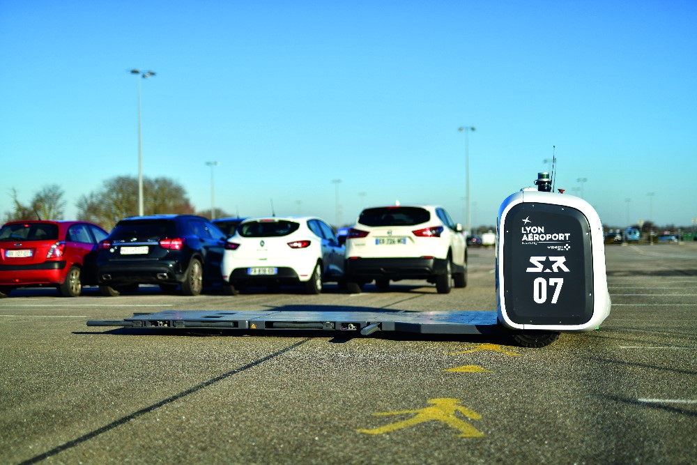
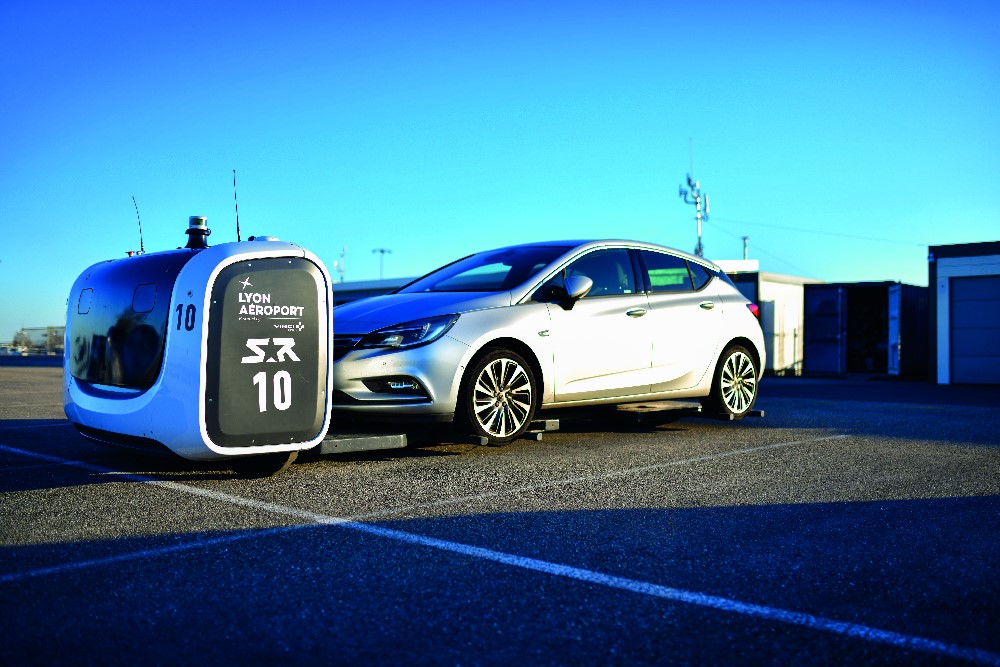
Stanley Robotics Stan UGV
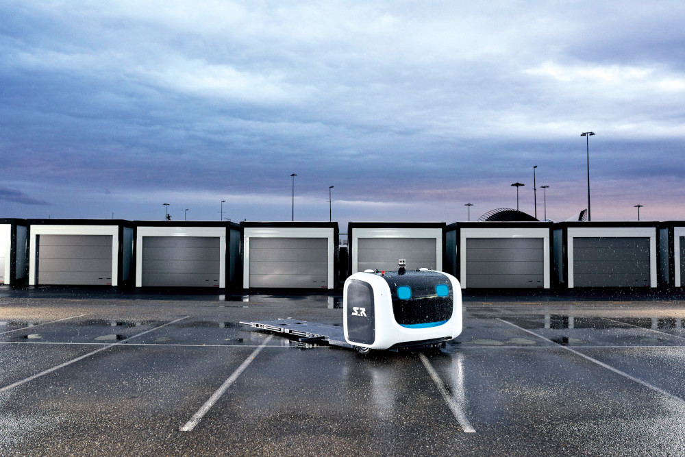
(Images courtesy of Stanley Robotics)
Parking. Fine
Rory Jackson learns about the development – and benefits – of this driverless valet
The advent of self-driving cars is predicted to bring benefits such as more energy-efficient mobility, traffic reduction and reduced collisions, and all the necessary technology to do so has probably been invented by now.
The key bottleneck with delivering these benefits worldwide is therefore not strictly technological but logistical. It takes decades to fully replace older generations of cars with newer ones, and the hardware and software costs of mass-producing self-driving cars make the global transition to full road autonomy something of a hard sell.
If, however, a company could package all the necessary tools for self-driving into some kind of turnkey mobile robot, that robot could theoretically ‘clamp’ onto (or interface with) any road vehicle as needed. It could effectively turn that vehicle into an autonomous system, and all the benefits of autonomy would be deliverable to drivers without needing to overhaul the global automotive industry.
That was the idea formed by Clement Boussard, co-founder and CEO of Stanley Robotics in early 2010, and the description of the original core concept behind the company’s flagship product, the Stan autonomous mobile robot.
The system is currently being used by customers around the world as a self driving valet solution, picking up parked cars (mostly outside the parking lots at airports), installing them in designated parking spaces, and later retrieving them for drivers as needed.
“City centres are less congested than they used to be, and at hotels and restaurants people actually prefer a human valet providing a personalised service,” Boussard says. “But at major international and large regional airports, the use of an autonomous service provides huge value in three main areas.” The first of these is of course convenience for departing passengers.
Finding a parking space can be a lengthy and stressful process, particularly when running late. Having an autonomous fleet of Stan UGVs can allow drivers to leave their car at any convenient drop-off point and head into the airport terminal, knowing it will be stowed and retrieved appropriately.
Second, an autonomous parking robot reduces the risk of collisions or other accidents in parking lots, and virtually eliminates any risk to people, as they are never required in the parking area.
Lastly, Boussard and his team found that while major international airports make most of their non-airline revenue from duty-free sales, regional airports make most of theirs from car parking.
With empty cars being parked by robotic valets, no car doors need to open or close, meaning more cars can be packed together in a long-stay car park.
“Very rarely can airports expand, so for many of them, using our Stan UGV is the only practical way to increase their parking densities. That can then allow them to offer more routes, and gain more passengers and hence revenue,” Boussard says.
“We calculated that it would cost about e15 million to build a multi-storey car park for 1000 vehicles. Meanwhile, we have shown that we can add the equivalent of 1000 vehicles parking spaces to a 2000-space long-stay car park for e7.5 million by increasing the parking density by up to 50%.”
While the Stan weighs 1.8 tonnes, it is capable of lifting vehicle weights of up to 2.6 t, and the company plans to increase this capability in future versions. It measures about 2 m wide, with the length varying between 4.4 and 5.9 m depending on how it has to adjust for the wheelbase of the vehicle it needs to pick up and park. The Stan’s speed is currently limited to 3 m/s, which is used largely on straightaways when away from vehicles and people.
To date, the Stan has been trialled at major international hubs including London’s Gatwick and Charles de Gaulle in Paris, and it has active customers at large regional airports as well as applications such as automaker logistics and train station long-stay car parks.
Deconstructing Stanley
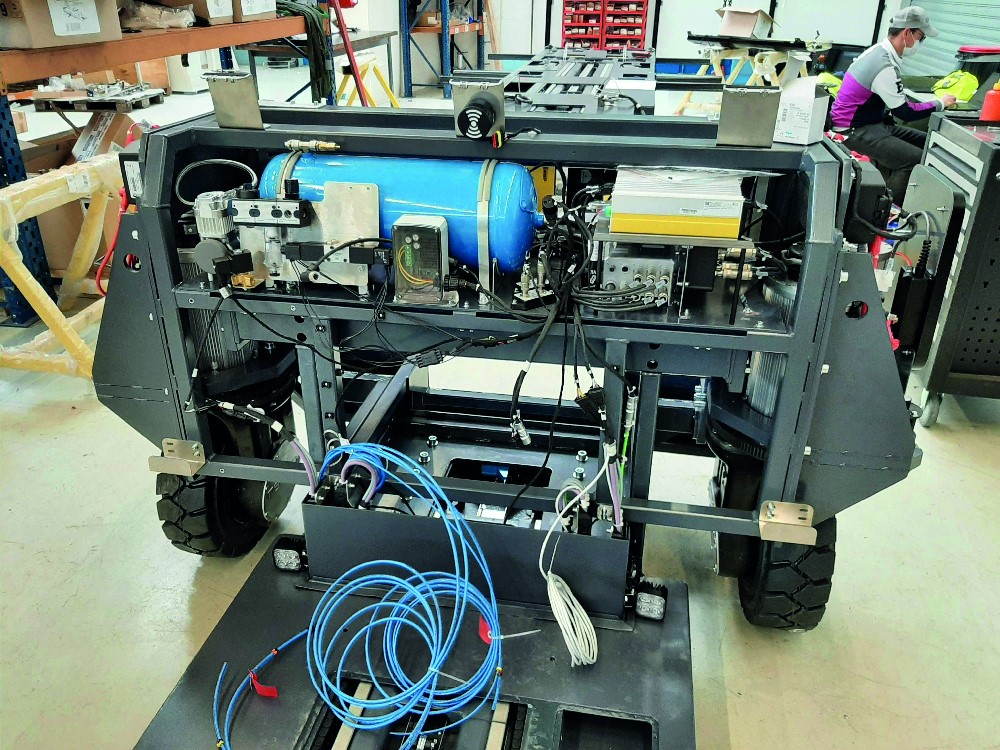
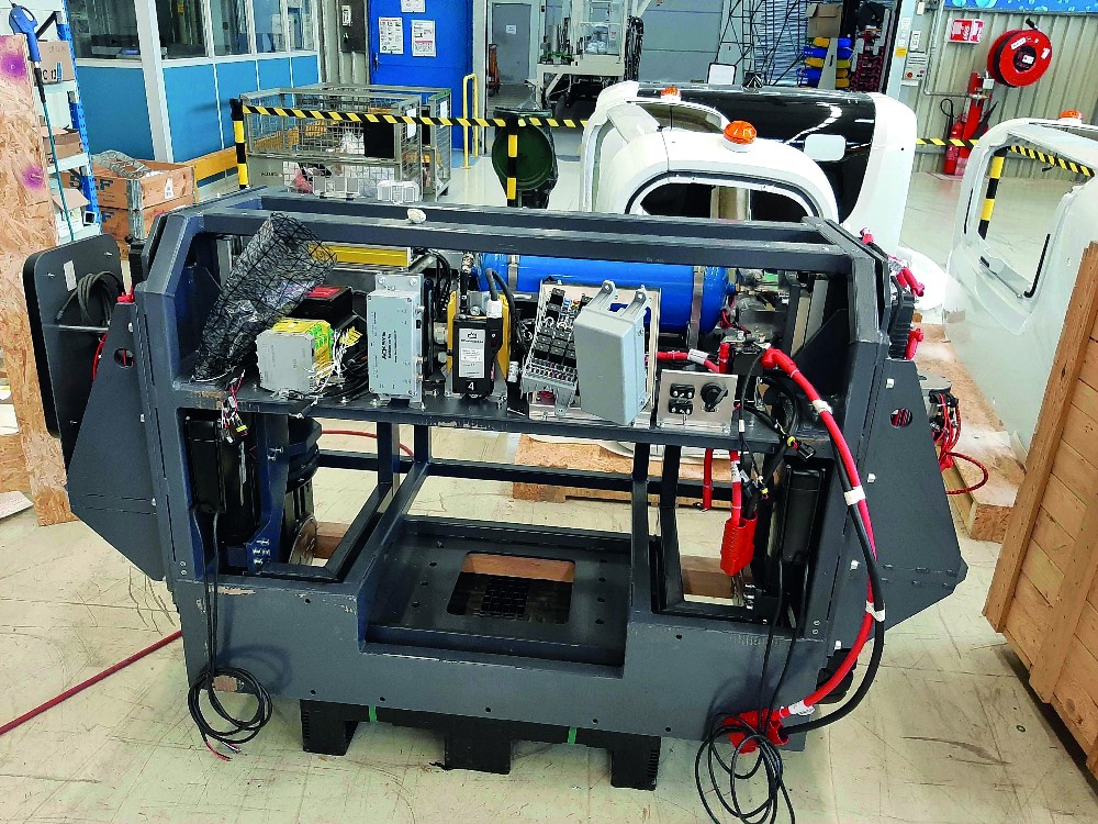
Most of the critical components of the Stan sit in the ‘head’ – its bulky housing at the front of the vehicle. The components include the electric motors for traction and steering near the sides, the battery packs sitting at the bottom, and all the electronic components sitting above.
The electronics consist of the main PC running the Stan’s embedded software, and various ECUs processing its internal Ethernet and CAN comms between the main PC and subsystems. On the very top of the head are a Velodyne Lidar, two GNSS antennas and two wi-fi antennas.
Behind the head sits a 1 m-wide platform, which can be divided into a fixed half at the midsection of the UGV, and a mobile half at the back that extends to meet the wheelbase of the car or van to be parked. As well as a small Lidar at the very back to prevent rearward collisions, various electronic, electromechanical and pneumatic systems are installed about the platform bed to execute the lifting and parking jobs.
Stanley Robotics’ engineers carried out extensive r&d to optimise the Stan’s hardware and software. As Anthony Trouble, head of robotics engineering, puts it, “The electrical harnesses contain about 1000 different wires, and our embedded software totals about 65,000 lines of code.
“And since the ground clearances under some cars are incredibly narrow, we had to design the platform to be as thin as possible. That was the major mechanical constraint, and is why we’ve
used pneumatics in some cases where electromechanical actuators would have taken up too much space.
“That makes sourcing some components challenging, but in future versions we plan to go thinner still nonetheless, so we’re constantly running sizing studies and other research to facilitate that. We’re often working in tight conditions and carrying extremely heavy loads, so building up the
right methodology and tools for all the design, simulation and prototyping has been critical.”
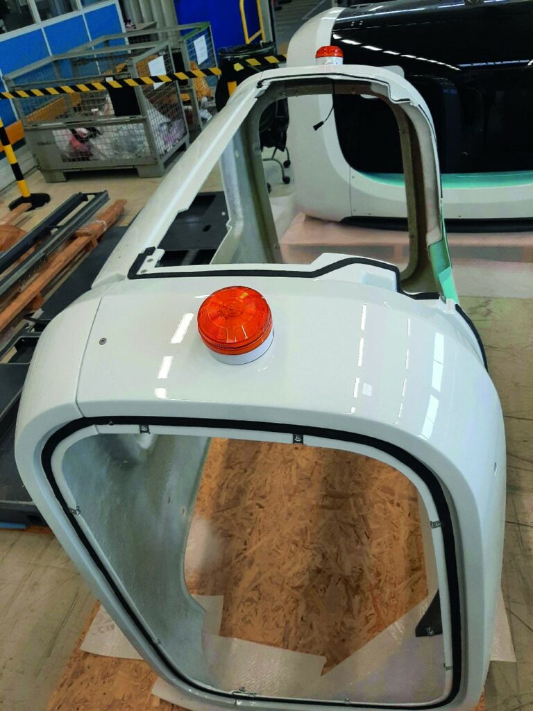
To ensure a robust chassis for the battery, the powertrain and the heavy loads they must carry, the Stan is made largely from steel. The parts used are high strength but not the highest available grades, as these would be prohibitively expensive and make sourcing replacement componentry for maintenance difficult.
“It also means we can cut parts to the shapes needed for the unique look and feel of the robot,” Trouble notes. “The front fairing is currently fibreglass composite, but we might pick something simpler for that in the future, such as stamped sheet steel.
“We are also starting environmental impact studies of the materials we use. As a result of our early findings, we intend to remove all stainless steels from future generation Stans: they use chromium,
which can be highly toxic as well as energy-intensive to produce, so we’re switching to galvanic steels instead.”
Being an outdoor vehicle with a very low floor, early tests revealed that the electric systems could often get flooded in rainy weather – 10 cm of rain can be enough to cause internal flooding. “So
everything less than 10 cm from the ground is IP67-rated – all the connectors, harnesses and so on,” Trouble adds.
“We work with Genaris, a proven producer of automotive- and military grade wiring harnesses, although the connectors come from several other suppliers. Getting the sizing right is important, and no one company as far as we know can supply in bulk for the voltage and ruggedness we need.”
Car-handling mechanisms
The Stan’s actual physical grip is achieved by the flatbed platform beneath it and using what are essentially four electromechanically deployed forklift like structures that snap about the tyres. Each of these consists of two rods, aptly referred to by Trouble as “pliers”.

Once a car that needs parking is identified, the Stan drives in front of it and starts sliding its platform under its front wheels by reversing towards it. The rearmost pliers are initially ‘retracted’
so that they point backwards to pass through the gap between the front wheels, and are then deployed outwards.
The mobile part of its platform extends pneumatically until all four pliers touch the fronts of the car’s tyres. Then a second group of pliers is deployed, one behind each tyre, spaced so as to ‘pinch’ all four tyres to secure a tight grip on the car.
“In the first prototype, the Stan used a system of cylindrical actuated rolling wheels to ‘scoop’ up and under the car’s wheels,” Boussard recounts. “We realised during trials though that this approach expended too much energy and needed too much ground clearance.
“But we could still lift 80% of the cars, and proved that the concept worked and was profitable for airport owners. So we continued our r&d until we arrived at the optimised solution we have now.”
Once held securely, the car is lifted into the air using two mechanisms. One is a pair of electrically powered jacks at the head that lift the front of the platform; the other is a pneumatic cushion in the mobile platform that is inflated to lift the back of the flatbed (the required thinness of the platform made using a jack impossible at the rear). The cushion sits atop a pair of roller wheels that keep the platform from dragging along the road from the weight of the car.
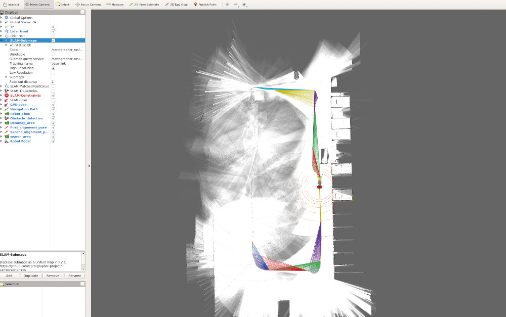
SLAM and sensors for parking
A considerable amount of sensor data and software intelligence is required to ensure the various mechanical systems can be deployed and used effectively.
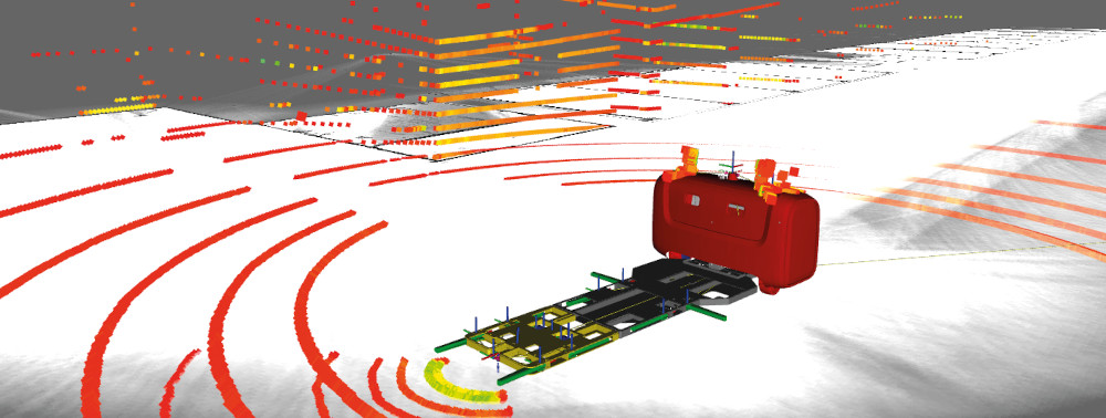
The primary perception tool here is Lidar. Velodyne Puck Lidars are used for real-time world mapping and obstacle detection around the Stan, although Stanley Robotics tests and benchmarks new Lidars as they come out, and the company says it maintains ongoing discussions with 10-20 Lidar suppliers to enable such testing.
“Most often we’ll ask them to send Lidar data recordings, then we analyse them and check them with our own algorithms, and where possible qualify the quality of the data signal,” Trouble explains. “If we think there’s potential, we borrow a Lidar, install it on a test version of the Stan and trial it for a few weeks to decide if we want to go further.”
As lengthy as the process is, the crucial importance of high-quality Lidar to the Stan’s operations make it essential, and as solid-state Lidars hit the market and become more affordable, Stanley Robotics anticipates doing more and more such testing in the future to select the right model.
Since the Stans have to operate in dynamic and constrained environments, developing SLAM capabilities was vital. Early versions of the company’s SLAM were based on the Hector SLAM approach, but these algorithms produced errors such as the ‘corridor effect’ in which robots cannot determine their longitudinal position in lengthy corridors or streets, or give 90º false headings in square-shaped rooms.
Odometry sensors were installed to mitigate those, but Stanley’s engineers nonetheless developed an optimal algorithm to prevent errors occurring in the first place.
“We have now designed a brand new SLAM module based on the Cartographer algorithm,” Trouble says. “It required a lot of adaptation for our use-case though, because the availability of landmarks change a lot throughout each of the Stan’s routes, and landmarks are key for the localisation aspect of SLAM. We’ve run lengthy tests of it, shadowing it with our GNSS readings and our previous SLAM 3D models from older SLAM algorithms, and the results have been great.”
Both the front and rear Lidars are critical for obstacle detection, but the forward one is more important for forming 3D point clouds for SLAM processing. “The rear one cannot do that as well, because we don’t spend enough time moving backwards to map in that direction,” Trouble notes.
“But it can verify vehicles and other objects recognised by the front Lidar, especially since the Stan reverses into vehicles to slide the platform under them afterwards.
“That’s when the rear Lidar becomes indispensable. Sometimes the clearance between a car’s left and right tyres is barely more than 1 m, so to fit our 1 mwide platform beneath it, we need a millimetre-accurate point cloud that is updating in real-time to hold the central axis as we slide in.”
Both Lidars are key for lining the Stan up with the central axis between a car’s left and right wheels, with a wide field of view and high point density being critical performance values. To ensure the timely deployment of the pliers, contact sensors detect when the front most pliers touch the car’s front tyres.
Once contact with both tyres is made (with onboard algorithms checking for false positives) the first set of rearward pliers are deployed, and the platform starts to extend backwards until both rear pliers touch the fronts of the rear wheels.
Additional onboard algorithms provide a confidence index to gauge how reliable the SLAM readings are in real time, by comparing incoming readings with what should be expected based on the Stan’s position in the known, embedded map.
“We also have ultrasonic sensors about the platform as a further verification that we’re maintaining tight contact between the pliers and the wheels, and not straying either side of the central axis,” Trouble notes. “If touch is confirmed across the first four pliers, the final four can then swing into place simultaneously, and the lifting system can do its job.”
GNSS
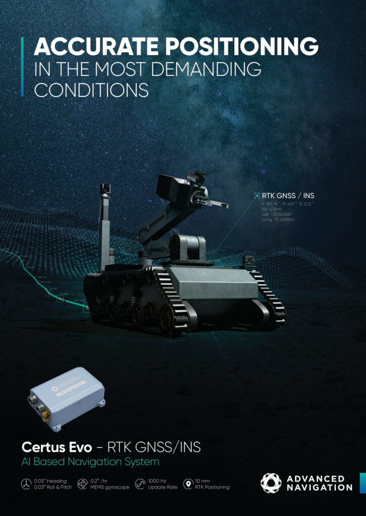
When moving between cars, parking spaces, charging points and so on, for SLAM to work reliably the Stan can rely on GNSS for relatively simple localisation and guidance (compared with SLAM). That said, precision guidance and localisation are critical for tight parking of cars and most other driving tasks, so RTK-GNSS is used to ensure centimetric accuracy of position in real time, with dual antennas for up-to-the-minute heading calculations.
Initial GNSS data is received via Trimble antennas and receivers. Every centimetre of space saved during the Stan’s valet parking is additional value to Stanley’s customers, so every centimetre of GNSS accuracy counts. Also, as position and heading are calculated at the head, a tiny error in either reading could result in a bigger mistake being made at the tail end of the platform.
A dedicated GNSS ECU takes the signals coming from the GNSS antennas and receivers, and makes them readable by the main PC. The PC also handles the RTK corrections produced by Stanley’s stationary hardware.
“Part of the infrastructure for the Stans includes RTK base stations installed on-site to enable the real-time GNSS correction updates,” Trouble says. “We propagate the corrections over wi-fi, and the robots process the corrections to compute the more precise GNSS coordinates and headings.”


This localisation information is combined with the SLAM data as well as the odometry coming in from wheel sensors, all on board the main PC. This is to ensure the Stans can constantly navigate roads and parking spaces closely and safely, both when indoors without GNSS and outdoors where SLAM-navigable landmarks might not be available.
Computation
The main PC is a rugged, embedded computer built around an Intel Core i7 6700 TE CPU. At the time of writing, no GPU had been installed but Stanley expects to choose and integrate one before next year.
“The reason for that is that we actually have six very small HD cameras installed about the head of the robot,” Trouble says. “They’re only used right now for remote supervision over wi-fi, so that if the Stan fails to compute something going on around it, we can view what’s happening and potentially intervene from our offices in Paris.
“But we’re using machine learning at the moment to develop computer vision for really detailed real-time perception of its surroundings, through which we’ll run the HD video coming from those cameras, and a good GPU will power it. It’s just that graphics cards are currently very expensive and in short supply, so we’re waiting for that to change.”
The network architecture running between the computation units forgoes traditional segregation and layering. The entire software architecture is ROSbased, with the necessary timing and arbitration for SLAM and other job-related decision-making defined through the software design. The ECUs meanwhile largely provide acquisition and translation of data between CAN and Ethernet.
Trouble notes however, “While the SLAM intelligence and collision avoidance is processed on board, the actual navigation waypoint and commands for the Stan to carry out jobs or head to its charging station are determined by our fleet management system – which interfaces with the enduser’s computer network – and delivered from that program to the local Stan fleet via our comms infrastructure.”
Comms and fleet management
In addition to the RTK base stations, Stanley Robotics typically installs a server to interface with the end-user’s IT network, along with some wi-fi relays to ensure the on-site Stans can in turn interface with the latter.
Surveys are conducted before each installation to ensure the appropriate placement of server and relay antennas amid the layouts of buildings and other potential disruptions that airports and other transport hubs can pose. That said, most customers’ car parks are largely open areas, so objects blocking or reflecting RF signals tend to be rare.
“That end-to-end interfacing ensures that key business data is recorded for the end-user, such as in-and-out timings of their customers’ vehicle bookings,” Trouble says.
“Our choice of wi-fi modems and relays, from Acksys, means that even if the end-user’s IT network drops out momentarily, the Stans are still connected to our server, so they can keep operating. We might just refresh the orders and requests from the end-user to the robots after their network comes back up.
“That said, if the wi-fi link to a Stan cuts out, the robot itself will stop immediately, for safety’s sake. The loss of RTK corrections alone is enough to trigger an emergency stop.”
When a request for an autonomous valet comes in from the parking lot, the order is transmitted through the on-site IT network to the fleet management server, which then assesses which Stans are available and suitable for fetching the car in question.
All the data links are encrypted through AES-256 over SSL, while the exact frequency depends on local regulations. For EU customers for example, Stanley technicians have to install a 5 GHz link, while for Japanese customers, 2.4 GHz links have to be used.
With localisation data being constantly assimilated by the fleet management software, appropriate waypoints and trajectories are calculated to optimise tasks and routes. The software arbitrates which UGVs should go for recharging, which should go to pick up a parked car, and which routes should be taken to drop off cars at appropriate spaces and prevent traffic.
Driving and braking
To execute the navigation orders received from the fleet management system, two asynchronous electric motors are installed: one for steering and one for traction.
The traction motor is capable of up to 3.6 kW of power, while the much smaller steering motor outputs up to 800 W. A single-speed gearing system with a 17:1 reduction ratio is integrated between the wheels and each side of the traction motor.

Traction power is delivered and adjusted by an inverter from Curtis Instruments, selected for the levels of high power throughput critical for energy-efficient acceleration as well as regenerative braking.
Energy comes from a 48 V battery composed of two packs, which together contain close to 20 kWh of energy when fully charged. It is supplied by E4V, which notably uses lithium iron phosphate (LiFePo4) cathodes in its cells, as it says they are very stable in terms of raw material prices and operational safety compared with other options. It also says they last far longer and are safer than NMC cells, albeit with a lower specific energy.
“The availability of our fleets is not primarily constrained by the UGVs’ battery energy divided by power consumption, because we can do opportunity charging all day long, sending them to recharge depending on the workload,” Trouble says.

“We are constantly recouping energy through the regenerative braking. At peak we can regenerate a total of 700 A, or around 30 kW.
“We send speed commands from the main PC to the Curtis inverter, and make sure those are as smooth as possible so as not to waste battery life with unnecessary spikes. The inverter draws current from the battery or the motor/ generator depending on whether the speed command is asking for acceleration, deceleration or cruise control.”
Intensive fine-tuning of the regenerative braking has been critical for optimising the battery’s energy efficiency and endurance as well as the handling of the UGV. All the braking is performed electromagnetically through the motor/ generator, without any conventional shoes, pads or pumps installed. A mechanical brake is installed at the motor level solely for the emergency stop functionality, and this can also be remotely activated if a Stanley Robotics technician observes a technical issue or is notified by a customer of one.
“We’re very satisfied with this braking concept, and the motor power works fine at 48 V, but if we increase the speed and payload capacity of future Stans, we might need to go to higher voltage architectures,” Trouble says. “It’s just a bit of a pain to make that leap, because of the changes it will entail for maintenance and installation requirements.”
Stan 2.0
Stanley Robotics now has several British and French customers, and more recently it has partnered with Mitsubishi Heavy Industries to develop its business throughout Japan and Asia.
“We want to move into the US next, but the main challenge there is that many American vehicles are bigger and heavier than European and Asian cars,” Boussard says. “The Ford F-150 is a big problem in this regard, and it’s really popular throughout the States.”
To handle these vehicles, the next generations of the Stan will be designed with different platforms and more powerful drivetrains. Some structural updates might also be necessary for enhanced load-bearing, longevity and synchronicity with available parts for maintenance in the US.
As mentioned, these future versions will also incorporate new products such as solid-state Lidar and new GPU models as they come out. The company also anticipates its ground infrastructure either evolving or right-sizing in the future. For instance, mesh radio networks between Stans could enhance the range and fidelity of fleet comms, and reduce the need for stationary repeater installations.
Being a robot designed around complementing the automotive industry, trends in that industry such as the growing popularity of SUVs, and large, heavy EVs with lower ground clearances, will push future designs towards thinner and more robust platforms.
However, faster, more energy-efficient Stans with higher carrying capacities will still be key as this translates to more parking work carried out per hour and per kilowatt recharged. Powertrain innovations will therefore remain a priority, and Stanley’s engineers hope to double the Stan’s operating and maximum speeds in the near future.
Specifications
Stan UGV
All-electric powertrain SLAM navigation
Maximum length: 5.9 m
Minimum length: 4.4 m
Width: 2 m
Height: 1.74 m
Kerb weight: 1.8 t
Carrying capacity: 2.6 t
Maximum driving speed: 3 m/s (10.8 kph)
Endurance between charges: 11 hours
Some key suppliers
UGV manufacturing and consultation: IMECA/Start2Prod
Batteries: E4V
Inverters: Curtis Instruments
Cable harnesses: Genaris Groupe
Electric actuators: Thomson Linear
Pneumatic actuators: Socafluid SAS
GNSS: Trimble
IMUs: Trimble
CPUs: Intel
Wi-fi: Acksys
Lidar: Velodyne
UPCOMING EVENTS


