


Sense and avoid
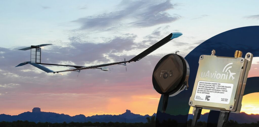
(Image: uAvionix)
Making sense of avoidance
Sensing other aircraft is a key requirement for UAS platforms, writes Nick Flaherty
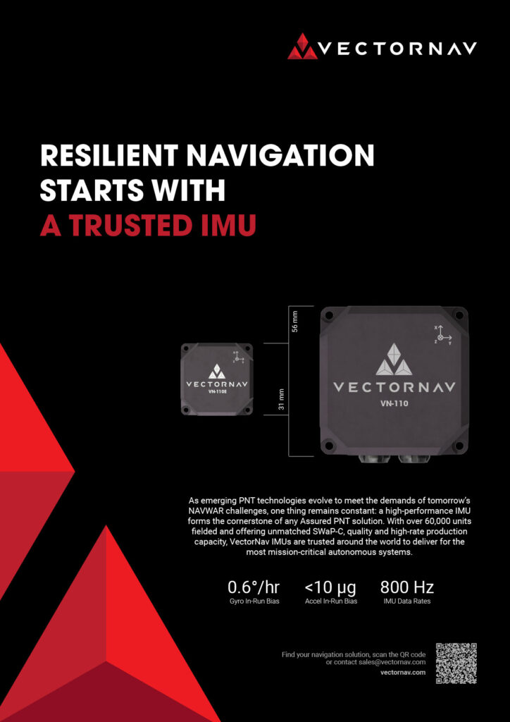
The ability to detect and avoid other aircraft is a key requirement for uncrewed aerial systems (UAS). Enhancements to the design of transponders now mean these devices can be as light as 15 g, allowing them to be used in the majority of platforms. However, the ADS transponder is a cooperative system that identifies the UAS to the air traffic management system, and relays that information to the ground stations of other UAS and other aircraft in the air.
Tackling uncooperative aircraft without a transponder – and even taking stationary objects into account for search and rescue – is a very different challenge, and one that is being met in a number of ways, from cameras to radar and even Lidar sensors.
There are between 15 and 25 mid-air collisions (MACs) reported in the US each year, although the reality with UAV collisions not reported is that number is considered to be significantly higher. With more delivery UAVs and eVTOL air taxis with autonomous operation planned, the need for detecting objects in the sky and against the ground is increasingly important.
Detecting non-cooperative aerial vehicles with efficiency and estimating collisions accurately are pivotal for achieving fully autonomous aircraft.
Concerns regarding MACs and near mid-air collisions (NMACs) are significant in uncrewed aircraft operations, especially in low-altitude airspace. Sense and avoid refers to the capability of an aircraft to maintain a safe distance from and avoid collisions with other airborne traffic. In conditions adhering to visual flight rules, pilots mitigate NMAC/MAC threats by visually detecting and then avoiding other aircraft to ensure safe separation.
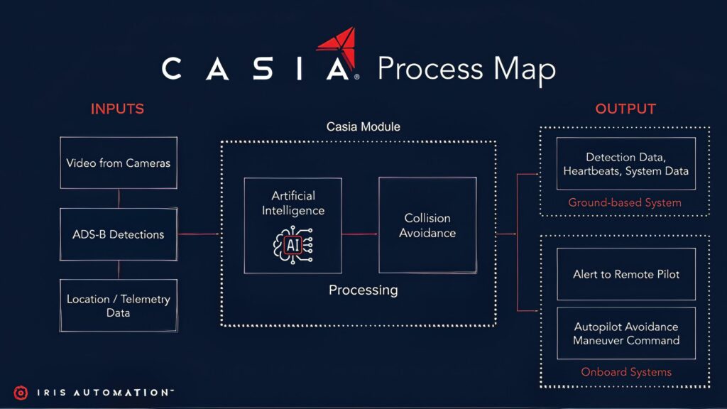
(Image: Iris Automation/uAvionix)
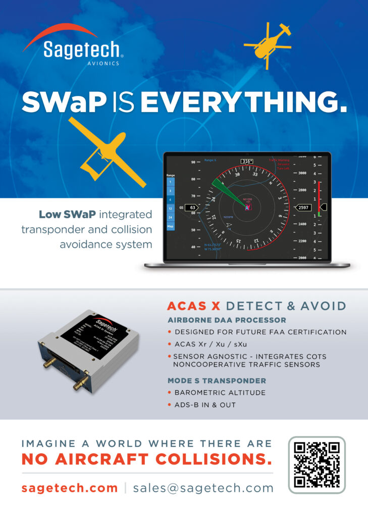
For medium to large airborne systems, active onboard collision avoidance systems, such as the Traffic Alert and Collision Avoidance System or the Airborne Collision Avoidance System, rely on transponders in cooperative aircraft. However, not all airborne threats can be tracked using transponders, presenting challenges for reliable operations in scenarios involving rogue drones, gliders, light aircraft and inoperative transponders.
Machine learning frameworks are increasingly being used with monocular cameras to identify objects in the sky while reducing size and weight, The data obtained by these image sensors, as well as the transponder data, are vital inputs for the autopilot
Transponders
One way to reduce the size of a transponder is to limit the operating mode. Mode A just transmits a four-digit code identifying the aircraft, while Mode C adds altitude data and Mode S includes heading and speed data. Some transponders only transmit, while others can accept data from other transponders in the sky.
(Image: TU Graz)
ADS-B Out Transponders: These devices weigh between 15 and 150 g and are primarily responsible for transmitting the UAV’s position and other data. They are necessary for compliance in mandated airspace and allow the UAV to be identified by other aircraft and air traffic control.
Mode S Extended Squitter (1090ES) is the international standard for ADS-B Out transponders, operating on the 1090 MHz frequency. It is mandatory for operation above 18,000 ft and is generally used in most international airspaces. Miniature Mode S transponders are the most common type for larger, professional UAVs.
Universal Access Transceivers (UATs) (978 MHz): UATs are a US-specific alternative, operating on 978 MHz. They are typically used for operations below 18,000 ft and have the added benefit of being able to receive free weather and traffic information (FIS-B and TIS-B) in the US.
The time it takes for a signal to travel from a transponder to a receiver provides information about the exact position of an aircraft. Depending on the class of transponder, further information is also transmitted, such as flight altitude or flight identification.
If a transponder has to deal with a particularly large number of interrogation signals, there is a risk of overload – the transponder may no longer reply to all interrogations and even may no longer respond at all to any interrogation. This can result in an aircraft disappearing from a radar screen for a short time. Admittedly, the risk of this happening is small, but it is present.
A tool has been developed that can simulate transponder occupancy in European airspace to assess the risk of this happening.
The Transponder Occupancy Analysis Software (TOPAS) tool not only looks at transponder signals but also includes the addition of new radar installations or changes to interrogation strategies to determine where any hotspots occur and if they need to be relieved.
A quick and approximate overview of the transponder occupancy is given by a relatively simple spreadsheet. It takes into account only the number of sensors and aircraft, but not their spatial distribution. The TOPAS toll acts as a digital twin, incorporating the actual positions of all radar sensors and also real air traffic situations. With such a simulation, even more complex interrogation sequences can be programmed both for entire radar systems and for isolated individual sensors. This gives more realistic and accurate results to specifically when and where there will be stress situations for transponders and what they might be.
This is used to make the use of surveillance radio frequencies and transponder critical resources more sustainable across European airspace.
Another tool, the EUROCONTROL Simulator of Surveillance Interrogators and Transponders (ESIT), allows users to estimate the transponder load in the local airspace caused by their own systems and those of neighbouring countries. The tool runs exclusively on EUROCONTROL’s air traffic control servers, so users will not have access to sensitive data of other countries’ infrastructure.
As the size of transponders and GNSS receivers reduces, more aircraft will use satellite navigation systems to determine their own position and automatically send it to air traffic control, which is also simulated by ESIT. However, this also needs to fit into new monitoring systems.
Multilateration (MLAT) works like a GNSS in reverse. Several antenna stations on the ground scan the transmitted radio signal of a transponder, sending their own interrogations to the transponder.
Depending on the distance of the aircraft, the radio waves from the transponder reach the respective receiving antennas at different times. Each receiving station reports the exact time at which it received the signal to a central computer. This allows the path of the aircraft to be followed.
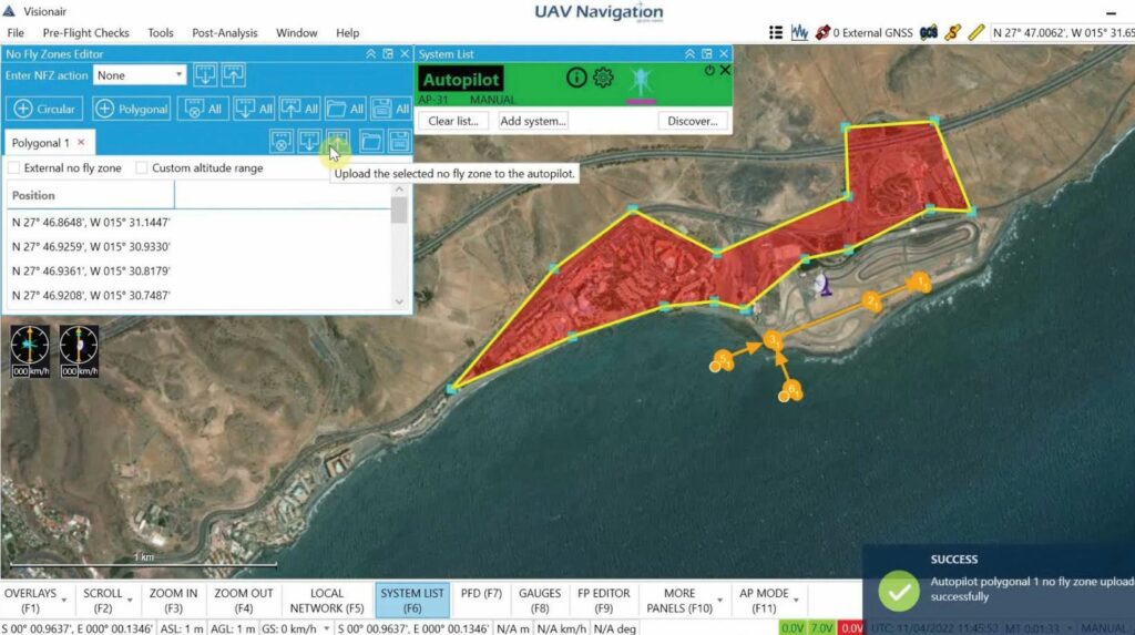
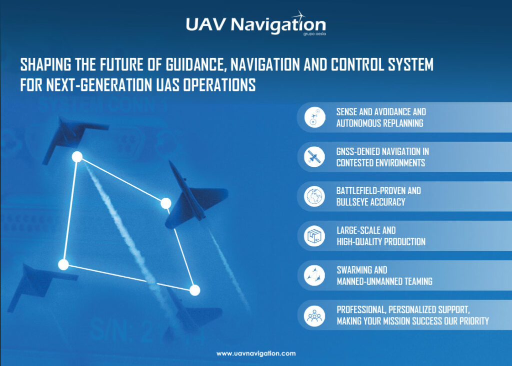
(Image: UAV Navigation)
MLAT systems can replace expensive radar stations, meaning that the failure of a single receiver is less dramatic than, say, the failure of an entire radar station. Despite these advantages, the ongoing radio contacts can put an extraordinarily high strain on transponders in a poor configuration, and can likewise result in an aircraft becoming virtually invisible.
ADS-B Transceivers
A transceiver combines the capability to transmit (ADS-B Out) and receive (ADS-B In). ADS-B In is an optional but highly valuable feature that allows the UAV or its remote pilot to receive data from other aircraft equipped with ADS-B, providing real-time traffic awareness information that is crucial for detect-and-avoid systems. Dual-band transceivers can operate and receive on both 1090 and 978 MHz, and can add a second antenna for transmission diversity. Typically, these weigh between 25 and 200 g.
Visual detection
Using off-the-shelf cameras is a key requirement for cost-effective visual detection systems. These range from a single monocular sensor weighing 180 g with a lens mounted on the nose of a fixed-wing UAV to six sensors located around the aircraft to provide coverage all around the UAS. The fixed single camera can provide an 80° field of view horizontally and 50° vertically to identify any aircraft likely to be in the path of the UAV.
The data from the camera are fed into a machine learning or AI framework to identify and track up to 60 aircraft or other potential obstacles at a time with the six-camera system. This also includes an ADS-B transponder to provide data to the autopilot. The AI framework is trained on images of aircraft and birds to distinguish between potential hazards and how they move; an airplane doesn’t move the same way as a hot air balloon or flock of birds. Identifying the object also helps identify how far away it is. For example, if an object is identified as a Cessna aircraft that is 11 m across and occupies 80 pixels, the separation distance is determined as 1.7 km.
However, the data can be location-dependent because birds may look and behave differently, and there may be new things in the airspace that require additional training.
For example, one site had a lot of dragonflies that can look quite similar to an aircraft at a distance. So, the system is trained to recognise that such insects are not actually a plane. The system is also trained on things it shouldn’t track such as vehicles on the ground.
There is more detail on the AI framework for visual detection below.
The system is being extended to operate at night by using the architecture to detect lights with the optical camera. This can support operation up to an altitude of 120 m (400 ft) and detect aircraft – including small planes and helicopters – up to a distance of 16.7 km.
Autopilot integration
A key factor is the integration of the sensor, whether the ADS-B or visual detector, into the autopilot and how the data are used.
One autopilot has a specific layer on the map so that the operator can see nearby traffic during missions. The system can perform an automatic mission without communications using a rule-based system and the data from the sense and avoid system.
(Image: University of Athens)
With an operator in the loop, the nearby traffic is visible, which could show as several aircraft and the colour will change depending on the risk of a collision, moving from blue to yellow to red to improve the operator’s view of the mission.
This step happens first due to the importance of sending the real-time information from the air to the ground control system. This is enhanced by the telemetry from the autopilot and that depends on the peripherals such as a transponder. The data from the transponder and the visual detection system can be combined on the same channel and converted to system parameters in the autopilot.
The system is designed not only to fly with an operator but – in case there is no datalink connection – it can perform automatic avoidance. Prior to the mission, the operator can tag the restricted zones and that information will be saved in the autopilot to use. The autopilot can automatically add waypoints to the route to avoid restricted areas around other aircraft and this takes into account altitude and airspeed; those restricted areas can be absolute areas but can also move.
Currently, there is no standard way to manage the conflicts between uncrewed and crewed aircraft, although as integration increases, the rules of the air, to which all air operators are obliged to abide, will need to incorporate protocols for shared airspace with uncrewed and autonomous systems. So, instead of waiting for a standard approach, the uncrewed aircraft has to move to avoid a conflict. This is configurable by the operator who may be managing several UAVs in the air.
If there is no possible solution to re-route the path to avoid a collision, i.e., the ‘advanced’ option, then the result is to loiter, remaining in a safe holding pattern that avoids other aircraft until it is safe to move on for ‘simple’ avoidance. This is all handled at one altitude and airspeed, moving laterally, without changing height or speed.
If all the calculations fail and the UAV enters a restricted zone, then it can automatically return to base or even trigger an operation such as a parachute opening.
These algorithms have to be useable on release and optimal to run on existing hardware in real time. This has ruled out large AI frameworks where simulation has shown the safest approach to be the rule-based machine learning algorithm.
This allows the algorithm to also be applied to uncrewed surface vessels in marine applications, integrating the AIS transponder with visual detection.
AI algorithms
Radar usage is often impractical owing to the size, weight and power (SWaP) limitations of UAS platforms, and machine vision with convolution neural networks (CNNs) has emerged as a promising avenue of research to address these challenges.
An AI framework with optical sensors for the detection, tracking and distance estimation of non-cooperative aerial vehicles provides depth information that is essential for enabling autonomous aerial vehicles to perceive and navigate around obstacles in real time using only the input of a monocular camera. The framework was trained on the Amazon Airborne Object Tracking (AOT) dataset, the largest air-to-air airborne object dataset with 5000 flight sequences captured from aerial platforms such as UAVs, helicopters and other air vehicles.
In contrast to previous approaches that integrate the depth estimation module into the object detector, this method formulates the problem as image-to-image translation. This allows a separate lightweight encoder–decoder network to be used for efficient and robust depth estimation. This object detection module identifies and localises obstacles, and then conveys this information to both the tracking module for monitoring obstacle movement and the depth estimation module for calculating distances.
The distance information provided in the AOT dataset was used to construct a large depth estimation dataset suitable for training an encoder–decoder deep neural network for depth estimation. This was integrated into the detection and tracking pipeline and evaluation of its performance on a large AOT dataset demonstrated remarkable accuracy.
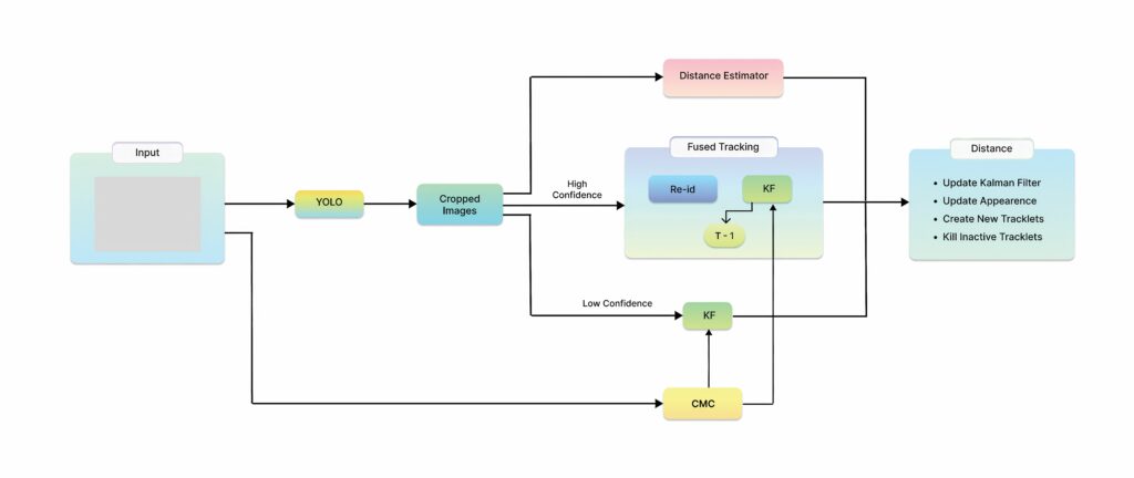
The CNN pipeline consists of multiple models, each specifically designed to effectively address the unique characteristics of detecting, tracking and estimating the distance of airborne objects.
The workflow starts with the input image being processed through the detection module. Following this, image sections containing aircraft bounding boxes are cropped to ensure that the bounding box remains centred within the cropped image, known as BBOX Cropping. Post-cropping, the images containing the detected aircraft are processed in the tracking component. During this phase, high-confidence detections are managed by the appearance Re-ID model, whereas low-confidence detections are handled by the Kalman filter (KF)-based motion model. Importantly, the KF motion model integrates camera motion compensation effects to account for the influence of camera movement. The tracking module updates the state of either the appearance model or the motion model, generating new tracklets to sustain the tracking of an aircraft or eliminate inactive tracklets.
(Image: University of Lisbon)
In parallel with the tracking procedure, the images containing the detected aircraft are processed in the depth estimation model. More particularly, these images are passed through the encoder network, which extracts hierarchical features by progressively reducing the spatial dimensions while increasing the number of channels. These encoded features capture various levels of abstraction, including edges, textures and object shapes. Subsequently, the encoded features are fed into a decoder network, which upsamples the feature maps to the original resolution of the input image. The decoder produces a depth map as the output, where each pixel corresponds to the estimated distance of the corresponding pixel in the input image from the camera. The final outcome of the whole pipeline comprises the tracked aircraft, inclusive of the bounding box of the detected aircraft, its associated track ID and depth estimation information.
This approach allows the training of the encoder–decoder depth estimation model. One assumption is that the bounding box strictly encloses information related to the object of interest, thereby excluding areas depicting the background. Nevertheless, the evaluation results show that the bias resulting from these assumptions is negligible.
Based on the distance information, the data are categorised into four classes as well as a background:
• First class: objects with a distance value less than 200 m
• Second class: objects with a distance value less than 400 m
• Third class: objects with a distance value less than 600 m
• Fourth class: objects with a distance value less than 700 m
• Fifth class: background objects with a distance value over 700 m
The proposed models trained using the AOT dataset exhibited promising results with regard to accurately discerning the distance values solely from a single image. This is an endorsement and a motivation to expose the models to other images and test their robustness by assessing their ability to perform reliably under conditions they have not encountered before.
Testing real-world flight scenarios shows unanticipated constraints and complexities that a supervised environment for training is incapable of addressing. Assessing a model’s performance in authentic flight conditions provides reassuring evaluation of the ability to adapt to unforeseen conditions.
(Image: Droniq)
Deploying a model trained using a benchmark dataset in a realistic environment can be a challenging task. The main reason for this is that the model might be exposed to an extensive range of data discrepancies that might occur because of different weather phenomena such as rain, fog and clouds, or hardware deficiencies such as colour quantisation, iso noise and others. These data divergencies could be conceptualised as domain shifts occurring in the latent space representation of the data.
Object avoidance
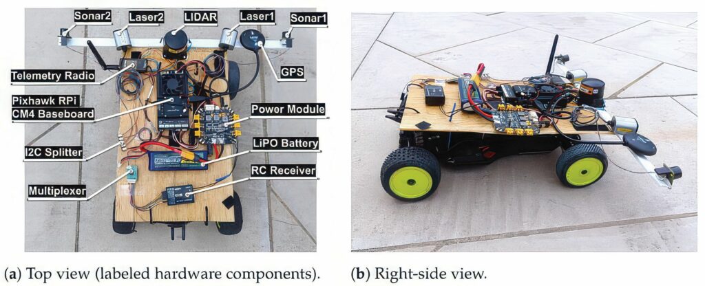
Another sense and avoid system combines low-cost components with two ultrasonic sensors, two laser rangefinders and one Lidar, together with a Pixhawk 6X flight controller and a Raspberry Pi CM4 companion computer.
This is aimed at small fixed-wing UAVs, typically under 25 kg that fly at speeds of up to 15 m/s. A collision avoidance algorithm utilising the Vector Field Histogram method was implemented to process sensor data and generate real-time trajectory corrections. The system, which was validated through experiments using a ground rover, demonstrated successful obstacle detection and avoidance with real-time trajectory updates at 10 Hz.
The use of body-fixed laser rangefinders for obstacle detection and avoidance in a quadrotor UAV was simulated, assessing the feasibility of different configurations regarding the number of sensors and installation angles. Lidar, characterised by allowing wider scanning angles, was also considered.
The ultrasonic sensors are a cheaper and lighter option for obstacle detection. However, they have a limited detection range compared with radar and optical sensors.
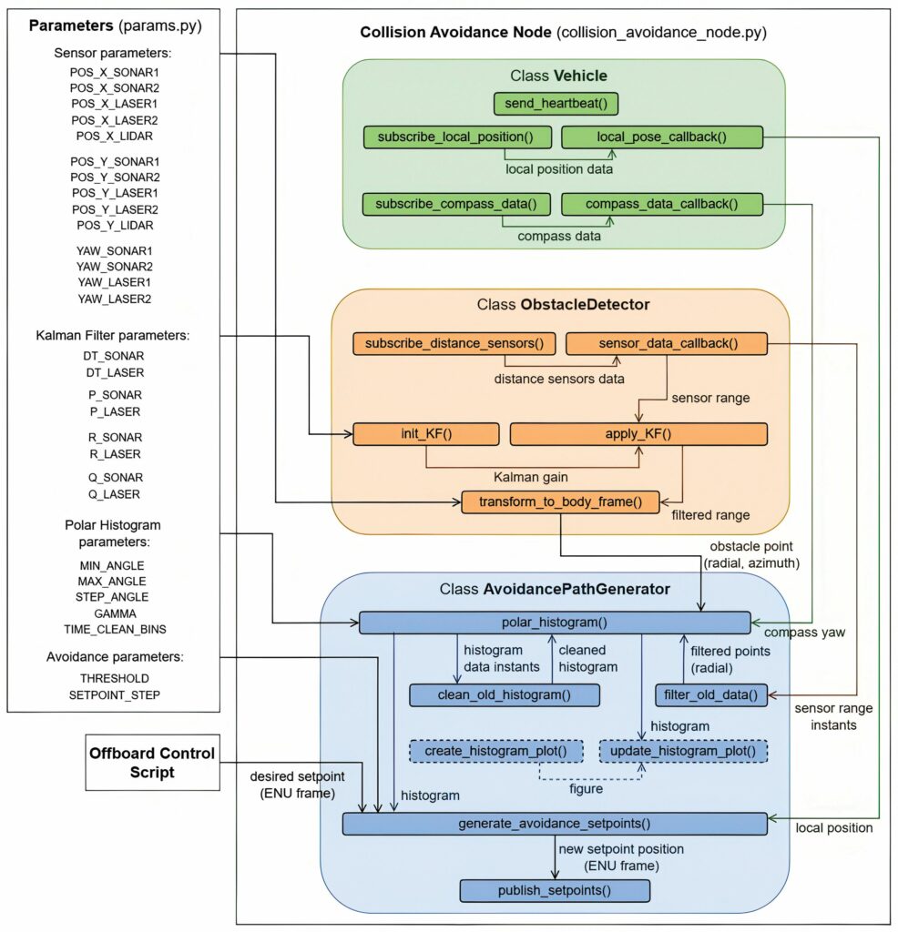
A key contribution was the implementation of a software solution for the system based on the adaptation of the open-source flight control software PX4, and the development of a software prototype to process sensor data, which compute obstacle positions and apply a vector field histogram algorithm for collision avoidance trajectory re-planning in real time.
The obstacle detection part of the software is implemented within the ObstacleDetector class in the open-source Robot Operating System (ROS). It starts with the subscription of five ROS topics, one for each sensor. This way, every time new sensor data are published on the corresponding topic, a callback function is called to save them in sensor-specific variables and process them. A one-dimensional KF is applied to the range measurements of the ultrasonic sensors and laser rangefinders that are within the detection range to smooth noisy sensor data and provide a better estimate of the true distance to the obstacles.
Testing
Given the risks associated with testing these new developments in a fixed-wing UAV in flight, a small uncrewed ground vehicle was used for initial testing.
For all cases, the obstacle was detected through range measurements between 2.8 and 4 m. Moreover, the KF performed reasonably for the lasers and ultrasonic sensors, reducing the noise and dampening the effect of outlier measurements that could lead the system to unnecessary reactions. Measurements of the ultrasonic sensors above 7 m were not considered for filtering because these sensors report their maximum range (7.65 m) when no obstacles are detected. Finally, the Lidar data were not subject to any filtering process but presented good results by detecting the obstacle at each scan.
While the rover-based tests provided valuable insights into the performance of the sense and avoid system, they did not fully replicate the aerodynamic and dynamic constraints of a fixed-wing UAV. For flight operation, future developments will adopt the Gazebo open-source robotics simulator, which allows for smooth integration with ROS and the PX4, including hardware in the loop where a simulation firmware runs on an actual flight controller board, such as the Pixhawk 6X.
The simulations allow testing of the system in the presence of static and dynamic obstacles of different dimensions and shapes, contributing to the refinement of the avoidance parameters.
Conclusion
The shrinking size and weight of ADS transponders and transceivers is allowing more UAVs to be detected in the air, but this still doesn’t address the issue of non-cooperative aircraft. Optimising CNN frameworks for real-time detection of images is allowing the use of low-power processing, which can detect all kinds of aircraft, even at night. For even closer detection, ultrasonic and Lidar detectors can be used with open-source software and low-cost hardware for effective avoidance.
(Image: University of Lisbon)
Acknowledgements
With thanks to Sebastien Mendez at UAV Navigation, Helmut Schreiber at TU Graz, Jason Hardy-Smith at uAvionix, Bruno Pedro at the University of Lisbon and Vasileios Karampinis at the University of Athens.
Detection range values per sensor type for measured data filtering
Sensor Detection Range (m)
Ultrasonic sensor 1–7
Laser rangefinder 1–50
Lidar 1–50
UPCOMING EVENTS


