


Schiebel Camcopter
Rory Jackson looks back over three decades of optimising a trusted flagship product
There is an adage among uncrewed aircraft engineers: “If your UAV doesn’t break in the first 100 flight hours, you’ve built it too heavy.”
Though outwardly humorous, it carries an underlying affirmation that the most critical ingredient in maturing and optimising a UAV is time. To fine-tune an aerostructure for the perfect strength-to-weight ratio, or an engine for its highest fuel efficiency and lowest vibration, takes copious trial and error over years of flight testing, analysis, simulation and repetition.
If a platform has not been flown to the point of error, such that its faults can be pinpointed and worked out of the system, one could argue that it needs more time before flying real-world missions, let alone being certifiable.
Schiebel has leveraged many different resources during the 30-plus years since development of the Camcopter began, including people, parts and extensive in-house machinery, but time has brought out the best in all of them. Through decades of r&d and iteration, the Austrian company has unearthed and cut out its flagship product’s flaws to the point that it has become one of the most trusted and commonly sighted rotorcraft on navy vessels’ main decks the world over.
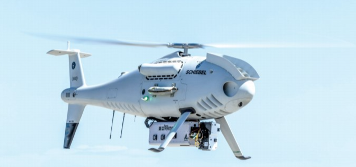
When we first spoke to Schiebel in late spring 2024, it had just completed factory acceptance tests of what it estimated to be its 523rd unit of the S-100 Camcopter. As of writing, the 200 kg uncrewed helicopter has flown with 40 customers globally, providing predominantly large naval and other military organisations with a wide range of autonomous sensing capabilities through its open, integration-focused architecture.
Users can benefit from its 50 kg payload capacity, an operating endurance typically exceeding six hours (varying with flight and weather patterns, although an external fuel tank can be added for about four additional flight hours), an optimal cruise speed of 55 kts and a top airspeed of 100 kts.
All this has made the S-100 desirable for frontier use cases, including US Special Operations Command (SOCOM), as Schiebel’s business development head, Neil Hunter, tells us: “We had a 10-year contract through Boeing as the prime, and we sold over 50 aircraft to SOCOM. We never found out exactly what they did with them; however, they definitely flew them in the maritime domain, and in an expeditionary sense, to great success.
“Although they lost some funding after Trump came into power and didn’t buy further units, we’re now re-entering the US market via talks and activity with the US Navy.”
Heading east, one sees Camcopters being flown by European, Middle Eastern and other Asian countries, as well as the Royal Australian Navy, and Schiebel anticipates closing its first contract with a South American country soon. This global network of customers is catered to from not only Schiebel’s Austrian head office and factory, but also from MRO facilities and partners in places such as the UAE, India and Australia, and its newest production and repair facility in France.
“And though 70-80% of our customers are military, and mostly navies, given our ability to autonomously land on moving ship decks, we’re progressing in several civil and commercial areas too,” Hunter notes.
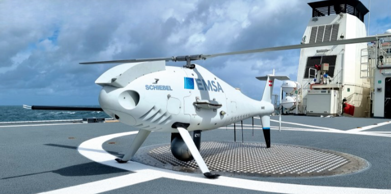
“Being able to carry a big, 10 in [25.4 cm], hi-res EO/IR gimbal means we can identify people that have fallen out of boats over great distances. Bristow in the UK, for instance, were the first people doing real search-and-rescue using S-100s in the English Channel, and we’ve had a big contract with the European Maritime Safety Agency [EMSA] since 2019 that has seen them deploy S-100s from Denmark to Spain and the Mediterranean, even on board German police ships.”
While most EMSA work has been ISR missions, a significant and rapidly growing application for the S-100 is emissions control. With the International Maritime Organisation having placed sulphur emission caps on ships in 2020, EMSA’s Camcopters increasingly fly with sensors capable of detecting and measuring dozens of different gases and particulates, and they autonomously follow behind commercial vessels recording their exhaust output as evidence to incriminate those polluting illegally.
“Helicopter flight crews hate the idea of hovering bored behind a container ship, mindlessly recording data and inhaling fumes, so it’s exactly what a UAV should be used for,” Hunter observes.
“These laws are recent, so it’s still a very new application, but EMSA’s getting very busy with it around Rotterdam and the English Channel, where you have possibly the most congested shipping lane in the world, and we’re already having conversations with users across parts of Asia, including the Indian Ocean, about manufacturing Camcopters for them to track ships that aren’t complying with these new regulations.”
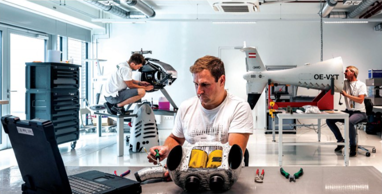
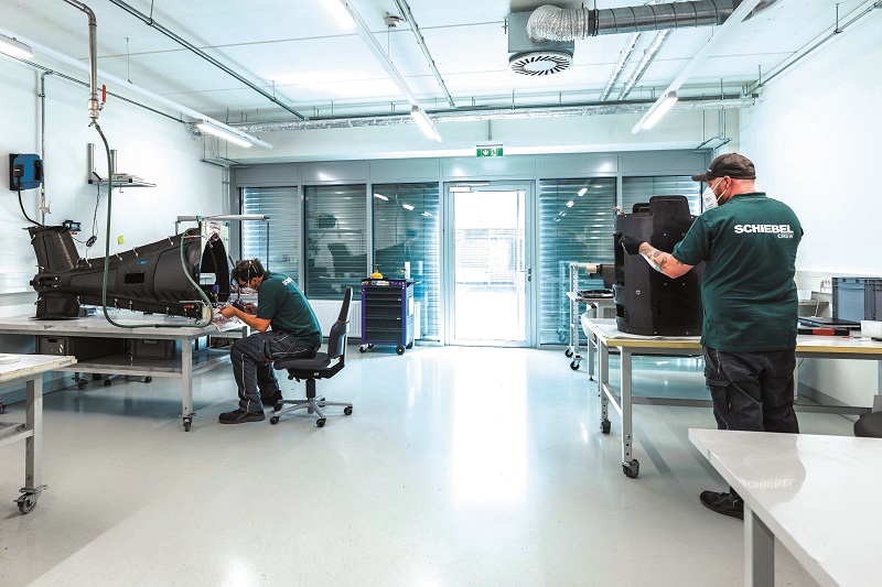
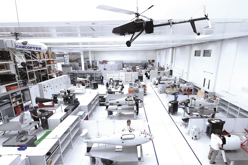
Around 40 minutes south of the Vienna head office, one finds the Schiebel factory in Wiener-Neustadt, built upon an airport where other aerospace entities such as Diamond Aircraft can trial new designs and components.
Built in 2006, the factory was expanded during the COVID-19 lockdown to double its capacity, with the company estimating that it would be able to construct more than 10 UAVs per month with great ease.
Actual production figures are dictated by a combination of contract sales and, to a lesser extent, r&d. A few units are always kept in stock for short-notice customers, as Schiebel persistently targets a delivery time of six months or less from the point of a new contract being signed.
“Every customer wants a slightly different configuration; hence we build per contract instead of churning out a fixed stock of units each year,” Hunter explains.
“It’s also why our CTO, Johannes Hecht, has spent the last several decades optimising the S-100 to be an open and modular solution, built around a very specific and optimised set of subsystems.”
From mine to UAS
Founded in the 1950s, Schiebel gained prominence in the 1980s as a maker of handheld mine-detection or mine countermeasure (MCM) equipment. Soon after, owner Hans Georg Schiebel pondered whether mines could be detected from an uncrewed helicopter.
As Hecht recounts: “It was around 1992 that he saw people doing aerial photography from model aircraft and, in 1993, Schiebel started a programme aimed at installing computers with intelligent mine-detection software on RC helicopters.
“Of course, back then, PC hardware the size of a shoebox had less than a fraction of the computing power of a smartphone today, and RC helicopters hadn’t the aerodynamics or engines to fly more than 300 m. But the resulting model vehicles were still enough for us to start flying and creating our first software models.”
The next three years of r&d saw Schiebel experiment with greater quantities of computing power and software, which meant upgrading to larger RC models, going from 1.5 m-long helicopters in 1993 to 3 m-long products in 1996, with engine power rising from about 2 hp to 10 hp.
“We also started learning how to better stabilise the helicopter via the control algorithms and software models,” Hecht continues. “Helicopters are unlike most fixed-wing aircraft in that they are inherently unstable – they always ‘want’ to crash – but step by step we wrote, installed and validated our first control loops.
“Those all came from completely blank sheets as there was no open-source world back then, and the few big companies who had helicopter UAV control algorithms, like Airbus and Boeing, guarded them as top secret, the absolute highest trade secrets.
“Post-1996, with three years of feasibility studies and development under our belts, we made a clear decision to formally design an original, stable, autonomous prototype to demonstrate aerial minefield detection for a customer.”
The Camcopter 5.1
That demonstration came in 1999, and included the prototype autonomously flying via GNSS waypoints while operating a mine-sensing camera; even flying in the ‘dead man’s curve’ – height and airspeed combinations defined in helicopter manuals as making safe landings under engine failures very risky – and sometimes just 30 m above landmines (too risky for crewed helicopters to try).
Key challenges along the way ran from figuring out how (in code writing) to first ensure the UAV could maintain a stable GNSS position and altitude before moving on to programming logical navigation from one waypoint to the next. Schiebel developed its own tools for calculating and simulating the aircraft’s dynamics as its 3.4 m-long prototype couldn’t be accurately modelled in the way that crewed helicopters (which were too big) and RC helicopters (too small) could.
“But, from day one, Schiebel adapted the development standards of the crewed helicopter world as closely as it could, from design to engineering and testing,” Hunter adds. “That’s been a big reason why we’ve been able to get all our certifications and other regulatory approvals today – because authorities can see the attention to detail that’s gone into the Camcopter from its earliest days.”
Nailing down these fundamental principles across numerous iterations was key to Schiebel finally unveiling its demonstration prototype, the Camcopter 5.1, to the public. It served a critical role in exploratory talks and trials for prospective customers to digest, and for Schiebel to find out how precisely they had hit upon what end-users needed.
Such interactions in fact unearthed far higher performance targets than Hecht and his team realised were needed, if serious contracts and users were to be secured.
“The 5.1 prototype could do maybe two hours of flight and had a MTOW of 60-72 kg, with a payload of around 10-15 kg. Its capabilities were state of the art for the time, and although we started by only flying over land, by 2000 we’d done our first flight trials with the US Coast Guard – the first shipboard operations using an uncrewed helicopter,” Hecht recounts.
“That proved we could do automated take-off and landing on a moving ship, which was totally unprecedented – especially compared with fixed-wing UAVs, which still need things like launch catapults and net- or hook-capture infrastructure, or lift motors, which cost efficiency – and it kept the workload on the ‘pilot’ very low.”
This had a significant impact on customer expectations. Upon seeing Schiebel’s UAV helicopter smoothly perform such computationally complex operations, they quickly realised that what they actually wanted was a minimum of six hours’ flight endurance while carrying a 25 cm camera, for three times the payload weight capacity of the 5.1, and, overall, a 200 km, real-time, long-range surveillance capability for each ship equipped with a Camcopter.
With the goalposts moved far (but conclusively), a three-year development plan for the S-100 started in 2003, as a completely new and optimised design, with none of the hardware or software to carry over from the 5.1, although new and optimised algorithms for fully autonomous VTOL on faster moving and rolling ship decks were one obvious target.
By the first customer trials in 2006, the first S-100 achieved many of the surface-level performance specifications still published today, including its minimum six-hour endurance (Hunter recounts that it set a new precedent for endurance that other, larger UAV helicopter OEMs begrudgingly had to catch up to) and 200 kg MTOW plus 200 km data-link range with its largest antenna.
This secured Schiebel’s first customer, the UAE Ministry of Defence (MoD), which bought 60 S-100s, convincing the Austrian company to embark on constructing its factory in Wiener-Neustadt, where Schiebel continues to produce its S-100s today, along with its S1 and S2 Wankel rotary engines, its composite material parts, and more.
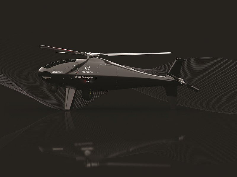
Anatomy
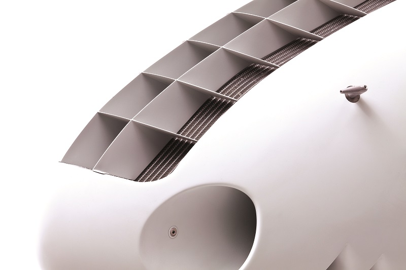
The S-100 broadly follows traditional helicopter design. Its engine and management systems sit near the front, driving the main and tail rotors via either one’s gearbox, which are installed at the centre and tail, respectively. The engine’s cooling radiator is installed atop (and aerodynamically conformal with) the nose, while the main fuel tank sits centrally, rearward and lower down than the main rotor gearbox.
That fuel tank is a carbon monocoque design and also functions as a structural component of the helicopter fuselage, a patented innovation by Schiebel, aimed at improving strength-to-weight ratio. On top of this, it sits at the approximate centre of gravity (CoG); hence, the CoG remains immobile throughout flight as fuel burns.
“Looking closer, there is also a freewheel assembly between the engine and main gearbox, which gives us our autorotation capability,” Hecht says. “A carbon-fibre driveshaft from the main gearbox runs into and drives the tail gearbox, the latter being a very standard, 90° conversion design. All the prop blades are Schiebel-designed as there’s never really been COTS or standard blades for a helicopter this size.”
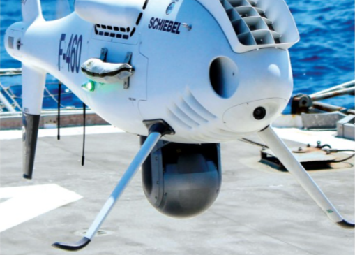
A main payload gimbal with up to 50 kg capacity is typically installed at the undercarriage below the main gearbox, with additional payload integration space available in the nose, inside the tail and off the sides in the case of some systems such as synthetic aperture radar (SAR). Hecht notes that the tail section is especially empty as standard, and 10-15 kg can be mounted there without affecting flight stability.
To power payloads (as well as avionics), one alternator is installed on the engine shaft, while another runs on the main gearbox’s output shaft, such that even in autorotation at least one alternator will continue generating electrical power.
Two batteries are installed onboard with 85 Wh each for a balanced DC bus output, but for weight efficiency, the S-100 is not yet fully electric or loaded with heavy battery packs, and autorotation can significantly outlast battery capacity; hence the alternator strategy.
A single flight control box above the fuel tank and behind the main gearbox contains the redundant avionics for flight management, the payload management system, power-supply boards, redundant GNSS-INS and redundant data links. For traffic awareness at altitude, transponders configured for Mode IFF, Mode S, AIS and third-party TCAS data links tend to be installed as well.
“As a small, multi-purpose aircraft, you can’t really go 10 cm anywhere along the fuselage without finding an antenna,” Hecht comments. “There’s one GNSS antenna in the middle of the tail fuselage section, and another atop the tail rotor fin, with trees of data-link antennas about the fuselage because there will always be one shaded, based on the direction the UAV is facing.”

Mission systems
While the S-100 was principally built to carry big camera gimbals and perform ISR roles, Schiebel focuses on making the S-100 payload agnostic, and it has therefore integrated many sensors to many different ends without dictating to customers which mission systems should be installed (data processing and analytics in particular are customer-specific and left to the end-user to choose or tailor).
“We favour a few that we know are good; for instance, we’ve worked closely with L3 WESCAM in Canada over the years, and lots of our customers fly their 10 in MX-10 in the main undercarriage bay, but we’ve also integrated EO/IRs from, say, Trakka and Teledyne FLIR,” Hunter says.
“With 10 kg of payload capacity in the nose, around nine out of 10 customers ask for a front-pointing Sony camera for the operator to use and step in if manual avoidance ever becomes necessary, but EO/IRs can also go in the nose. The UK Royal Navy S-100s, for instance, have an L3 WESCAM MX-8 gimbal there.
“We’ve also nose-mounted Overwatch Imaging’s PT- and TK-series sensors. The latter notably scans to surrounding horizons like a radar, but by using three different cameras of three different wavelengths and resolutions – they can do maritime surveillance, terrain analysing [and] wildfire analysing sensors – it’s quite a spread of capabilities they do.”
At least two radars have been flown, including Leonardo’s PicoSAR and Thales’ I-Master (the former being side-mounted and used by an Asian customer for maritime domain awareness, while the latter typically sits in the undercarriage of the UK Royal Navy’s S-100s). Both are SARs, and crucial for ground-moving target indication (GMTI), maritime moving target indication (MMTI) and target tracking through clouds during obscure weather conditions. Hunter adds that IMSAR’s SARs will soon be integrated for a couple of emerging contracts.

“On the entertainment side, we worked with the FLIR Systems Polytech Corona 350 II gimbal for a Hollywood customer 10 years ago, who wanted some very hi-res, high action cinematography. That was something of a one-off, but we still occasionally get asked about doing that sort of thing,” Hunter recalls.
Arguably, the fastest-growing market for the S-100 is anti-submarine warfare (ASW), driving r&d into how objects below the water surface can be detected and tracked from the air. To that end, the S-100 can be equipped with two 10 kg arrays of sonobuoys (totalling four) either side. RIEGL’s bathymetric Lidars have also been integrated and tested in shallow waters to great effect, potentially more for MCM than ASW.
Schiebel is also working with Thales France to integrate the latter’s ASW comms relay system. In that operation, a maritime patrol aircraft will drop a vast number of sonobuoys, while the S-100 aerially relays data between them and to a mothership. Lastly, Schiebel is in talks with an unnamed American company (via the US Navy) whose prototype sensor may be able to penetrate deeply below the waves for submarine hunting.
“And while transponders aren’t payloads, we will install anything from Modes 1-to-5 and up to Mode S, based on customer requests, and we’ve moved into ADS-B wherever possible, because right now that’s the only real way to give yourself some conspicuity to crewed traffic or ATC. There is still no real, standardised detect-and-avoid system for UAVs to comply with, as much as we expect it to come with time,” Hunter says.
The copter’s computers
The autopilot has been engineered in-house using raw materials, with INSs and GNSSs (from NovAtel) supplied externally. The air data systems and computer architectures for the flight computer (as well as the ECU and BMS) have been developed internally.
The flight hardware has remained largely unchanged since 2006, having been heavily future-proofed from early on to account for anticipated airworthiness requirements over the subsequent 20 years, with flight software updates being central to capability improvements in redundancy, safety, efficiency and payload compatibility since then.
“If you provide a certifiable flight computer to the customer, the hardware can no longer be changed, aside from very minor obsolescences,” Hecht says. “We essentially have three PowerPCs onboard, but in Version 1 of the flight software, two of the three PowerPCs were idle during flight, and just one did all the work.
“All the flight control, payload management, power management, data link management, video processing are all handled in the processing power of a single PowerPC. And the other two weren’t redundant systems; they couldn’t be made to function like backups yet.
“But, over the years, we expanded the software capabilities, raised the autonomy capabilities, activated the second PowerPC to take over some duties and serve as a redundant flight controller, and activated the third to take on all the payload management, leading to a better load distribution and good reserves of leftover processing bandwidth for new features today.”
Despite this space, Schiebel is researching how best to add a fourth PowerPC externally to the main three to carry the load of customer-specific algorithms (as companion computers increasingly do in UAVs).
However, the PowerPCs and their software have always been designed with open architectures, albeit with clearly defined interfaces, for customers to interact with the system, extract data, and configure protocols and functions for requirements such as new payloads or third-party ground-control station (GCS) software.
Flight control network
The computer processes flight data from the S-100’s GNSS, IMU, air data sensors, transponders and other mission-specific inputs (including position and heading relative to waypoints, be they preprogrammed or changed mid-flight) to ensure correct speed and direction.
Both are managed via a plethora of electronically controlled servo actuators; three act on the main rotor, one adjusts the tail rotor, and another actuates the engine throttle. Should one of the main rotor servos fail in flight, the software integrates extensive compensatory behaviours to keep the UAV as safe and stable in the air as possible (and Schiebel has judged for now that integrating a fourth main rotor servo would cause more issues than benefits).
Additionally, throughout standard flight, numerous software subroutines ensure the vehicle stays within the limits of safe flight physics, including laws keeping it from flying faster or slower than allowed, or exceeding safe angular rates.
The software model integrates comprehensive data on the helicopter’s capabilities, and on how dynamic adjustments to flight laws must be made based on the helicopter’s surroundings, with particular regard to ambient environmental conditions such as wind and gusts.
Hunter adds: “People sometimes look at our flight control arrangement and mistakenly imagine applying it [unfavourably] to a crewed helicopter, but they don’t realise that with a UAV, you have a completely different situation. If, for instance, a crewed heli’s tail rotor malfunctions mid-flight, that’d be hell for the pilot, but if that happens in the Camcopter, it actually doesn’t matter.
“The S-100 can spin, it can lurch, it can autorotate, and it remains completely controllable throughout all of those; there’s just no-one onboard to suffer flight sickness. And pilots need to look out the windows to see where they’re landing – the Camcopter doesn’t care. It can land backwards, it can land while tilting; it doesn’t need any outside visual cues. We can afford to operate completely differently than crewed helicopters, because the UAV can do things completely safely that might be dangerous for a piloted helicopter.”
Safe automatic take-off and landing on large and small vessels in all sea states first relies on the GCS, which is equipped with GNSS and IMU to measure and predict the behaviour of the vessel. For redundancy, third-party ship movement information can be fed into Schiebel’s system.
“The airborne platform then utilises its own dual GNSS and IMU setup, and the very specific and unique Schiebel-designed software algorithms and routines, while taking the behaviour of the moving platform and the aircraft into account, to perform the coupling of the aircraft to the moving vessel and its deck,” Hecht adds.
“This allows full automatic take-off and landing procedures. If, for any reason, it is desired by the customer’s operational concept, the open architecture can accept additional relative positional data from third-party sources, such as DeckFinder.”
While Schiebel has expertise in programming CAN and ARINC buses, data signals back and forth between the autopilot and the servos today continue to be carried over standard serial interfaces, such as RS-485, the company having found these to be highly reliable over the last 20 years and hundreds of thousands of flight hours.
“We tend to use whatever bus is in the servo actuators, sensors or payloads that a customer agrees to use, or insists on us using, so we have nothing against CAN bus. We understand its programming and advantages, and we’ll install it if it becomes necessary, as readily as ARINC 825, Ethernet or any other bus,” Hecht adds.
“Our architecture is open and so ready to adapt to any interface of the future. Maybe, if we talk again in two years, our standard bus will be totally different.”
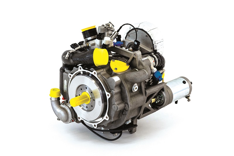
The S1 Wankel engine
For those asking themselves over the past few pages, ‘but why a Wankel engine?’, the answer is primarily that Schiebel’s engineers wanted to maximise power to weight and minimise vibration early on. Vibration especially would directly reduce the resolution and hence value of the UAV’s camera data, and given the highly vibratory nature of rotorcraft, any means of eliminating vibration sources was a must-have.
“We actually used two-strokes all the way up to the Camcopter 5.1, both single- and dual-cylinder designs, and with the first Wankel engine integration on the 5.1, that was how we learned that a Wankel was better for our purposes,” Hecht recounts.
The first S-100s were powered using a COTS Wankel engine core, modified with Schiebel’s own EFI, ECU and related components, as that COTS engine (manufactured nearby) was used in glider aircraft, meaning it was optimised to run for five to 10 minutes at a time, and not for the continuous six hours of operation that Schiebel aimed for.
“Its size and power worked initially, however, so we made all the ancillary systems around its mechanical core, and took out weight where we could. Being a crewed aircraft engine, it still wasn’t as light as we needed it,” Hecht says.
“But that supplier couldn’t support us as we took the engine in a different development path than what works for gliders, so we split off into mechanical development and started more or less making our own engine. Luckily, a Wankel doesn’t have so many parts. It’s a simple design compared with normal combustion engines.”
That first design was an AvGas-burning Wankel called the S1, although in 2009, Schiebel began designing a heavy fuel engine, as navies (especially in NATO) increasingly turned against taking gasoline to sea for safety reasons.
That resulted in the S2: the 23.7 kg, single-rotor Wankel in the S-100 today, which entered service as its standard-issue engine after nine years of r&d in 2018. It occupies 400 x 353 x 312 mm inside the UAV, displaces an effective 440 cc, and produces a maximum continuous 60 hp (44 kW) at a nominal operating speed of 7100 rpm. The system has been designed to run primarily on JP-5, JP-8 and Jet A-1, integrates redundant EFI and electronic ignition systems, and is oiled via a two-port, pump-fed, loss lubrication system.
Most importantly, as the thermal management approach has differed in every Wankel we have investigated, particularly with respect to cooling the highly sensitive needle roller bearing at the rotor, the S2 mixes its intake air with oil from one of two lubrication ports, and pushes this through a sealed aperture inside the rotor-bearing section (some readers may note a measure of similarity with that of Rotron’s RT600-HC).
“But also, after trying a couple of COTS rotor bearings, we ended up designing a bearing that was perfect for the specific forces, loads and thermal characteristics of our application,” Hecht adds. “It is manufactured to our spec by a specialist Austrian company, much as several other parts in the engine have been made or consulted on by companies and university departments with great knowledge of the problems we’ve had to solve, especially of materials and coatings.”
He adds that the rotor’s cooling fins have been extensively designed to maximise thermal transfer from the internal air-cooling system. Aspiration is performed naturally to prioritise simplicity and weight over the addition of turbo- or superchargers (although Hecht and his team have experimented at length with these, as with various approaches to direct injection and other potentially useful modifications). The housing, meanwhile, is liquid-cooled using a water-glycol jacket approach typical of 50-60 hp engines.
“Though we still sell some S1 AvGas engines, our long-term engineering focus is on the S2. Heavy fuel is really where the future of the S-100’s powertrain lies. Given the money and time to allocate, we may optimise it as a multi-fuel engine too,” Hunter notes.
From shaft to blade tip
The engine and rotors run at fixed rpms in operation, with the blade pitches adjusted by the flight controller to govern between ascent, descent, hover and forward acceleration or deceleration, with the adjustment optimised over the years for minimal power consumption.
“We’re a 200 kg platform, so in coarse wind conditions we can provide a lot of tail rotor thrust. Conversely, in forward flight, we barely need any,” Hecht notes.
“The engine’s output shaft connects to a freewheel assembly, which, as mentioned, is how we can autorotate, and the upper side of that assembly goes directly to the input shaft of the main gearbox, which functions as the central distribution system for mechanical power across the aircraft.”
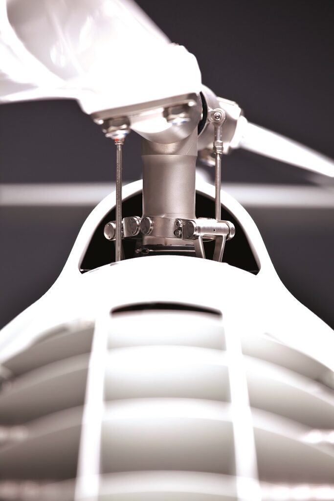
One output shaft atop the main gearbox runs into the main rotor head. Schiebel has opted for a rigid rotor in its main rotor configuration, being mechanically simpler than most, and giving faster control response due to its light weight and inertia.
“A part can’t fail if you don’t use it, so from early on we tried to strip out everything that wasn’t absolutely necessary with the rotor head, meaning all the stabilisers, hinges and so on that historical doctrine insists are necessary in rotor hubs,” Hecht says.
“Rigid rotor designs are aggressive and difficult to control from an engineering point of view, and you need a lot of software to stabilise them, but once you have them under control, they’re very stable and really robust against CoG movements. We have asymmetrically mounted 25 kg payloads on the side, and it’s been no issue for the flight control – only once have we ever needed to add a kilo or two of ballast.”
With the main rotor head being hingeless, each of the two blades is affixed to the hub at two points, with the blade material and variable pitch of the rotors taking care of aspects of flight dynamics that are typically trusted to hinges, stabilisers and a human pilot. Much of those parts are typically needed for a human to feel the helicopter’s behaviour, but the flight software senses changes in movement accurately enough through the IMU to react in milliseconds by altering acceleration, pitch, roll or yaw.
“The head is made from titanium, so it is extremely strong and it’s hollow, so we could put a sensor in the rotor head to feed data back to the autopilot. We’ve even put a SATCOM in there before with good results,” Hunter notes.
The proprietary blade design targets a medium between torsional stiffness and flexibility, partially to compensate for the lack of hinges, and the blades are mostly manufactured in-house, with some third-party facilities being leveraged when orders exceed capacity. A standard, prepreg, carbon/fibreglass material is used for the blades, with the resin and the method by which the composite is formed via the autoclave being key to the blades’ mechanical properties.
“There has been a huge learning curve since we made our first blades in 2008. For instance, in our early days, we’d find after flying and landing in rainy conditions that the blades were pitted all over their leading edges, and the more we flew in rain, the faster we were going through rotor blades,” Hunter recounts.
“So, Johannes’ team came up with the idea to fix a nickel leading edge made by a third-party on our rotor blades, including on the tail rotors, which effectively stopped that problem. We’ve continued using and adapting that design since, and it’s great for the longevity of our rotor blades.”
A second output shaft on the main gearbox powers the carbon-fibre driveshaft running to the tail gearbox, as mentioned, and a third output shaft powering an alternator. As well as gears, the gearbox contains a lubricating oil bath and dampening shafts. The latter smooths vibrations from the engine’s peaks and troughs of torque, being the main source of what little vibration a Wankel produces.
Body matters
Weight and aesthetics were the priorities in hull design, with Hans Georg Schiebel personally working on making the S-100 look like something navies and similar professional outfits would want to fly. The first submission from a commissioned design house was favoured by himself and his company, with minor optimisations made for cooling and similar needs.
“The Camcopter 5.1 was a cluster of modules, which together flew very smoothly, but didn’t look at all like a serious tool for professional organisations,” says Hecht. “Optimising for weight, aerodynamics and resonance were important, as was designing for efficient manufacture later on, but we quickly learned in our early days – as much as some might not want to believe it – that customers buy UAVs with their eyes as much as with the datasheet and flight tests.”
Internally, the structure is engineered as a single monocoque part, which directly integrates the fuel tank as well as mounting brackets for the engine, the main gearbox and avionics modules, as well as bearing the torsional and vibratory loads of the main rotor.
“A lot of simulations and strength analysis calculations went into making sure the structural materials and design would serve those purposes, although there weren’t too many CFD or CAD tools for aerodynamics 20 years ago,” Hecht adds.
“So, a lot of test flying was key for measuring relevant forces, and all we had to compare that against was basic literature telling us what to expect. The early structures were maybe 1.5 times heavier than they really needed to be, but with time and experience, we reduced all weight down to the absolute minimum we could, with just little tunings here and there today.”

Material world
Carbon composite is the main structural material, although a few fixtures of fibreglass composite are also used, and fixtures in the drivetrain are machined from high-strength aluminium, which, like the titanium rotor head, provides tensile strength advantages over carbon.
The electronics are largely housed in aluminium housings for their combination of EMC-shielding and strength-to-weight advantages (including for the main avionics box containing the autopilot, power supply, data links and so on).
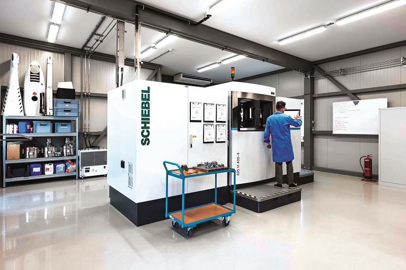
As well as all carbon-fibre production and autoclaves being kept in-house, Schiebel has acquired metal additive printers (from which the titanium rotor heads are printed), and the company’s r&d department uses these to examine how weight may be removed from even highly loaded parts, such as the main rotors and landing gears.
“They are laser sintering machines, which we can also switch to print using aluminium, and so a big future step will be looking into how all the aluminium parts could be redesigned through additive printing. It will really bring a new dimension to getting weight out of the UAV,” Hecht says.
The composite parts are modelled in CAD, with that data fed directly into the automated prepreg cutting machines, which Schiebel reports as being more accurate than past manual cuttings. The moulds are manufactured from aluminium by a third party owing to their size, although the designs are generated in-house before being delivered to the third-party manufacturer.
Once the carbon is laid up on the moulds, sufficient parts for a single S-100 can all fit within a single autoclave, and if necessary the cured parts can then be machined to exact tolerances in-house. After being checked and validated for quality control, the parts are painted by an external company (they and the mould supplier are subject to change, so Schiebel declines to name them) and then assembled in the final UAV product.
Data links
The UAV and its payload sensors are the primary shading obstacle for direct, continuous C2 with the GCS. To circumvent this, Schiebel typically installs an omnidirectional antenna at the aft-most point of the hull, which provides 270° of comms coverage centred about the rear, and a +120° sector antenna at the nose coverings for the remaining 90°.
“For redundancy, a second data link is installed, which always works at a lower frequency than the primary set, varying as these do with customers’ band requirements, and an omnidirectional antenna at the underbelly provides the uplink and downlink for that second radio,” Hecht adds. “There will sometimes be a tiny bit of shading from the main payload gimbal, but never enough that there are any significant consequences.”
Although COTS antennas were used during the prototypes leading up to the Camcopter 5.1, those used in the S-100’s primary and secondary C2 links are heavily customised for optimal opening angles (the area within which the majority of the radiated power is available), mounting, vibration tolerance and a variety of performance parameters.
Additional data links are typically integrated based on customer requests, covering various types of video feeds, comms relays, transponders and encryption solutions, which Schiebel approaches much as it would mission payload systems.
The result is normally about four different data links per UAV to ensure all sensor information is transmitted smoothly and uncorrupted to the ground, and Schiebel aims to use COTS antennas for the ancillary data links (and also for GNSS signals) as far as possible.
“Much of the customisation in our data links in the past had to do with saving weight, as back then we even had to use bulky Mode S transponders originally designed for crewed aircraft, but it is much easier today to find radios for UAVs that are really small, lightweight and power-efficient, and using Sagetech’s MXS and MX12B transponders have similarly helped save our SWaP budgets,” Hecht notes.
“Overall, I’d say avionics’ SWaP parameters have gone down by a factor of two to three over the last five years. It’s the same on the payload side: performances have gone up while sizes have gone down, and though we originally had to make our own gimbals because no-one made one suitable for our size requirements, Schiebel has been able to shut down its in-house gimbal production and focus on more important areas because of third-party suppliers of high-quality gimbals multiplying.”
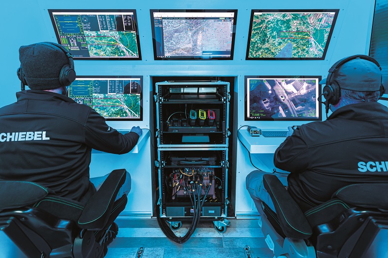
Control interfaces
While Schiebel has designed its own control station software in tandem with the development of the S-100, its open architecture and interface control document enable straightforward integration with any third-party software suitably configured for communicating with and commanding the UAV.
“We aim to open the architecture more in the future to allow more types of third-party commands, including UTM software, swarm management systems or STANAG-compliant interfaces, for instance,” Hecht adds.
“From early on, we realised an open architecture was going to be important, but the Camcopter also has very specific capabilities; for instance, when flying under severe environmental conditions close to a ship, or flying with the control station out of a moving truck, or performing very special flight patterns in combination with automated payload controls. Other UI software won’t always have integrated keybindings, control mappings or any other kind of inputs for those.”
“So it will almost always come down to a combination of Camcopter-specific ‘plugins’ – if you want to call them that – with the standard software of a third-party, should an end-user have a preference for mission planning and control management.”
Future
Around three decades have passed since Hans Georg Schiebel’s first vague idea of making an aerial automated mine detector, and two decades since development of the S-100 kicked off.
Hunter estimates that today as much as 20% of Schiebel’s annual turnover is reinvested into its aerospace engineering department, particularly towards integrating new mission sensors and capabilities, with ASW taking up most of this work in the last few years.
“When the Cold War ended, countless analysts declared that no-one was going to build submarines, but in fact there has been a huge growth in their number and use worldwide,” he adds.
“We’ve shown the S-100 can drop sonobuoys, USVs and micro-AUVs for closer detection in the water, and we’re about to show what it can do with surface-penetrating Lidar. And, while Johannes and his team are always looking for new r&d pathways to reoptimise or expand the S-100 towards navies’ latest capability requirements, we’re also expanding our product portfolio with the S-300.”
The S-300 is to be a considerably larger UAV for users with the budget and physical space to accommodate and benefit from its greater endurance and payload limit.
As of writing, it is expected to fly for up to 24 hours with a 50 kg payload, although up to 340 kg (including fuel) carry-capacity will be possible within the 660 kg MTOW helicopter.
Schiebel emphasises that the S-100 is probably not yet at mid-life, let alone being phased out in favour of the S-300: they are very different aircraft for very different use cases. The company continuously reviews the S-100 for opportunities to update a component or software module wherever possible, and also for signs of whether a design ceiling is ever truly being reached; for instance, if the core structure or software is at the limit of how far it can leverage the kind of cutting-edge technology its end-users want it to work with.
“If we ever do see the S-100’s design end in sight then we will likely take a deep dive into the core system concept, and make a totally new, uncrewed aircraft system from scratch,” Hecht muses.
“Then we will futureproof it, one module at a time, and flight-test it to failure as rapidly and repeatedly as we can, so that it is state of the art for at least the next 30 years, just as we did 20 years ago.”
Key suppliers
- Composite materials: In-house
- Engines: In-house
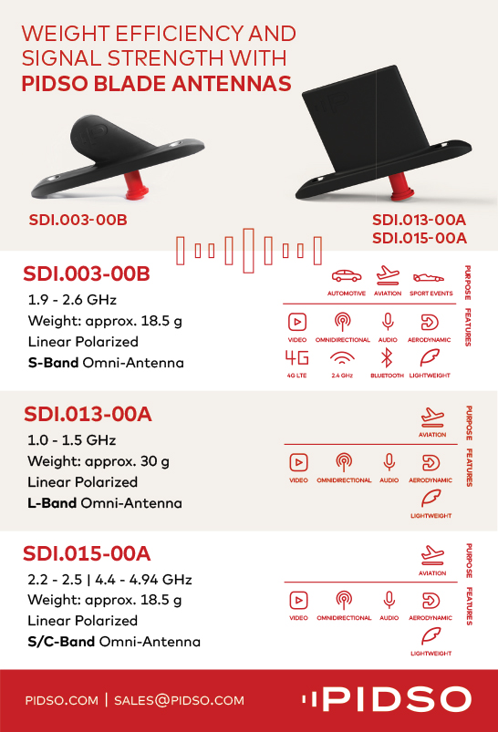
- Antennas: Pidso
- GNSS: NovAtel Inc
- Computers: Roda computer GmbH
- Transponders: Sagetech Avionics, Inc
- AIS receivers: Shine Micro, Inc
- Multi-sensor array payloads: Siemens
- EO/IR gimbals: L3Harris WESCAM
- EO/IR gimbals: Trakka Systems
- Wide-area optical sensors: Overwatch Imaging
- Emissions sensors: Aeromon
- Optical gas imagers: Sensia Solutions
- Synthetic aperture radars: Leonardo
- Synthetic aperture radars: Thales
- Synthetic aperture radars: IMSAR
- Bathymetric Lidars: Areté
- Bathymetric Lidars: RIEGL
- Sonobuoy replay payloads: Thales
UPCOMING EVENTS


