


Ray-tracing sensor tests
Simulators
Simulation firm rFpro has used ray tracing to develop software that can accurately reproduce environments to test sensors in autonomous vehicles (writes Nick Flaherty).
The company develops high-fidelity software for driver-in-the-loop (DIL) simulators, and 6 years ago started extending its technology to testing driverless cars. It has written a simulation engine from the ground up using ray tracing that traces all the beams that fall on a sensor. This can be visible light for a camera, infrared for a Lidar or RF for a radar sensor.
Using ray tracing allows artefacts such as motion blurring to be accurately tested in a virtual environment.
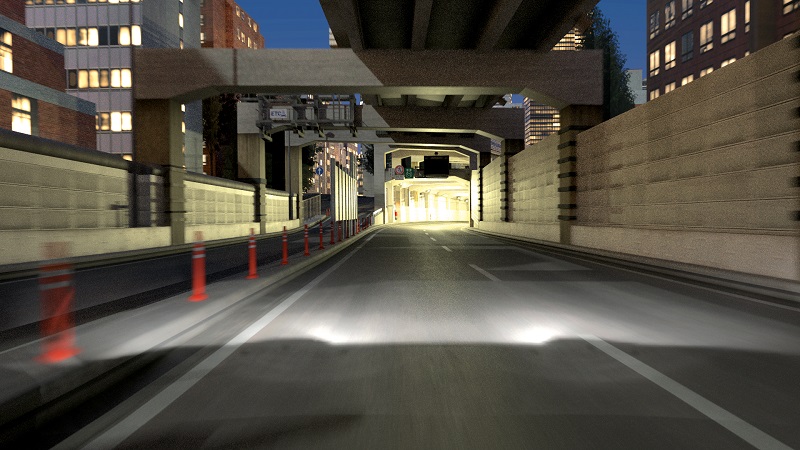
The simulation engine builds up environments, for example an underground parking garage or an urban tunnel at night. All the beams, or rays, in the environment are tracked, including those from external lights and from the vehicle, to recreate what is received by the sensor.
“We have spent 16 years creating immersive real-time high-bandwidth, low-latency simulation technology for human vision, which is what DIL simulators are all about,” said Matt Daley, operations director at rFpro.
“Until now, the fidelity of simulation in the most challenging lighting situations hasn’t been high enough to replace real-world data. Our ray-tracing technology is a physically modelled simulation solution that has been developed specifically for sensor systems to accurately replicate the way they see the world.”
“It needs to be engineering-accurate. You have to do things as physically accurately as possible. As soon as you move away from a perfectly lit daytime scene with lots of other light sources, and other vehicles, you have to be able to calculate how the light bounces around the environment. That is why ray tracing is needed for high-fidelity sensor simulation.
“Ray tracing is established in the graphics industry but it has been focused on making things look good to human eyes. We believe this is the first engine written from the ground up for sensors in autonomous systems.
“It’s all about the physics of electromagnetic waves from a source reflecting off materials and arriving at a sensor. It’s about how you trace the path.”
The model of the sensor is a key element in the simulation. For example, a camera sensor with a rolling shutter can use three capture periods, for example at 2, 5 and 10 ms, then process that data to give an HDR image. These timings can also change from frame to frame as the sensor adapts to the different light levels while the vehicles move around. That needs to be included in the model to achieve accurate motion blur in the simulated sensor.
“With rolling shutter sensors, every single line of the chip is being sampled at a slightly different time, so we don’t get straight edges,” said Daley. “That is fundamentally built into the way the sensor models are coupled with the ray tracing. What we have done is develop the ray tracer alongside the sensor APIs that allow the models to be integrated.”
This is tested in the lab using physical cameras that measure light intensity levels and colour reproduction against the simulation, with results within a single-digit percentage.
All the calculations are handled as 32-bit floating point data to represent the strength of the light beams. However, this is not a real-time engine, as the optimisations used for high-speed rendering in the DIL systems won’t work for the highest fidelity sensor simulation.
“We still need to be highly efficient with this sensor simulation though, so we make sure every ray we fire is used,” said Daley.
The ray tracing incorporates every element in a simulated scene, which has been physically modelled to include accurate material properties to create the highest fidelity sensor data. The rate of frame rendering is adjusted to suit the level of detail required.
That enables high-fidelity rendering to be carried out overnight and then played back in subsequent real-time runs if needed.
The simulations can all be rendered on a commercial GPU board in a PC, taking seconds per frame. The sensor models run on another GPU card, coordinated by the central processor in the PC. This can be extended to cloud computing systems with arrays of CPUs and GPUs to build systems with multiple sensors, as a driverless vehicle could have 40 or more sensors operating simultaneously.
The simulation is managed by a series of APIs. A vehicle API is used for the vehicle being simulated, with a traffic API for additional vehicles, pedestrians, bicycles and so on. Then there is a sensor API to link to the sensor model.
The multi-threaded rFpro simulation is also a synchronous system and waits for everything to finish before moving to the next step, which again prioritises accuracy and precision over real-time operation. A simulation thread controls all the objects and where they are, then there is an independent rendering thread to produce the ray data for the sensor models.
“We started this development at the time ray-tracing cores appeared on graphics cards, so the ray tracer has been designed for those cores,” Daley said. “We have more than 200 digital models, ranging from a 30 km section of a complex highway in central Tokyo to the controlled setting of Millbrook proving ground in England that shows the entire location.”
The simulation environment makes it extremely flexible to create thousands of tests, particularly the edge and corner cases that are difficult to reproduce in the real world, such as testing the flicker mitigation in the sensor.
“This represents a move away from proof-of-concept demonstrators for training neural networks using synthetic data to continuous development and testing for an inherently safe process,” Daley said.
UPCOMING EVENTS


