


Performance monitoring
(Image courtesy of Boeing)
Overcoming performance anxiety
Monitoring the performance of an uncrewed system is more important than ever. Nick Flaherty looks at the challenges of performance monitoring in the air and under the water
Monitoring the performance of uncrewed systems is becoming increasingly important to ensure their safe operation. Whether that be monitoring the health of UAVs making deliveries, underwater vehicles that would be difficult to recover if they encountered problems, or vehicles operating in harsh environments, the technology is increasingly being integrated into the overall management of the systems. This is achieved using existing sensors in the system but with alternative control software to provide additional information on the health of the system, allowing remediable actions to be taken if necessary.
All this also has to be part of the functional safety assessment of the system design and integrated with recovery strategies in the event of a problem.
Machine learning algorithms and artificial intelligence (AI) models are being used alongside sensors to predict problems so that repairs can be implemented before a failure occurs.
However, there are also key differences in performance monitoring for different types of uncrewed systems. UAVs in the air, for example, see more monitoring of the tips of propellers as well as vibration monitoring of the motors, while UUVs might be many miles from assistance or completely inaccessible, making predictive monitoring vital.
UAV monitoring
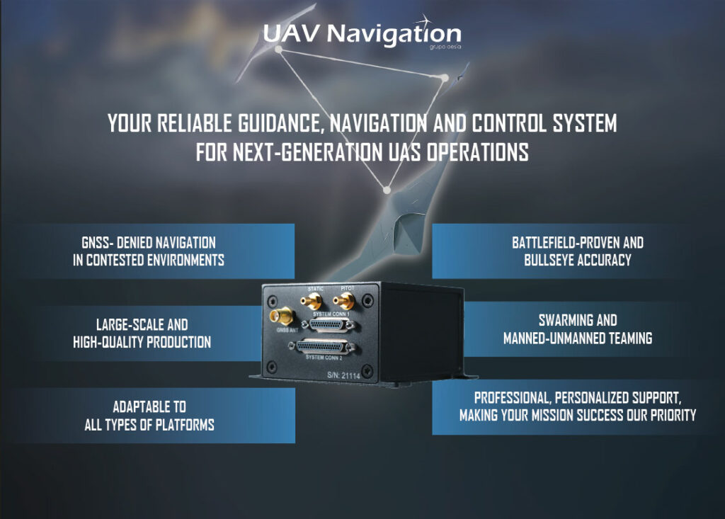
Performance monitoring is key for safe and efficient UAV operations and it requires a combination of sensor data, the autopilot and ground control software. These work together to monitor hundreds of flight parameters in real time and trigger automatic safety actions and alerts for an operator. This requires multiple layers of hardware and logic redundancy and self-checking features, all within the size and weight constraints of the system. The redundancy includes duplicated components, such as microprocessor boards and altimeters, as well as sensor fusion algorithms to ensure that the estimation of performance is precise. This means that even if a position sensor fails or GNSS is lost, there is another alternative such as moving to dead reckoning.
(Image courtesy of UAV Navigation-Grupo Oesía)
Layered on top of the hardware are continuous self-diagnostic routines that check the health of the sensors and other components in real time so that any anomaly is detected immediately to activate back-up systems.
A powerful approach to performance monitoring is predefined autonomous actions. This requires a highly configurable autopilot to allow users to set automatic responses to strategic sensors such as setting different threshold values for sensors for particular actions. This could be in the event of the loss of communications or if vibrations are high.
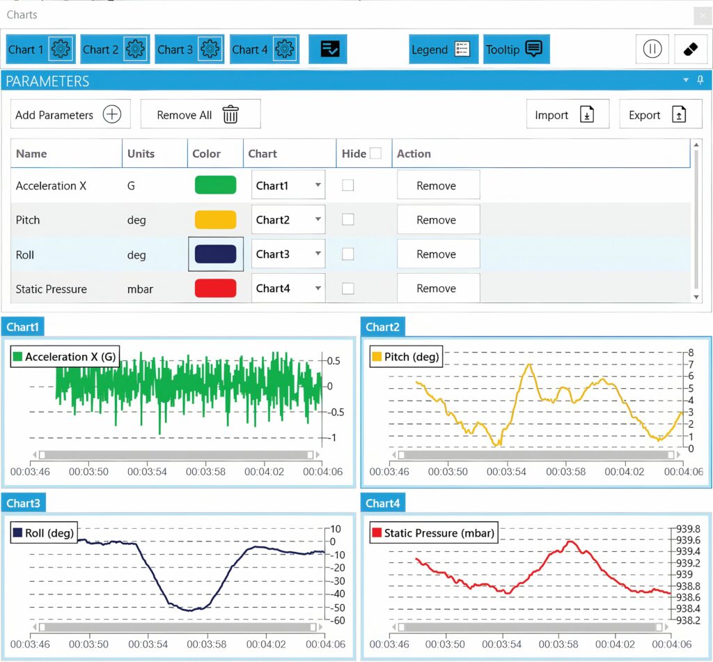
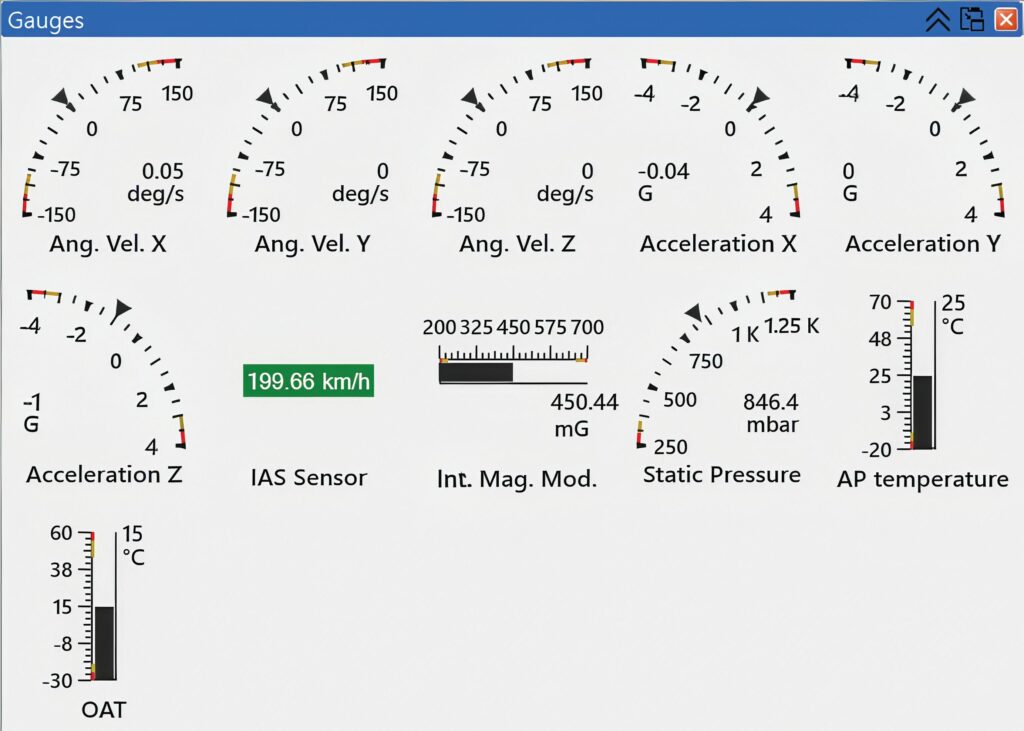
It means that an operator can define many different thresholds and customise the alarms, both in the UAV and in the ground station. However, multiple alarms can overwhelm a remote operator, so ‘light touch’ gauges can be used to visualise the alarms in different ways. These range from classic analogue and digital gauges to dynamic real-time graphics, allowing operators to switch views such as moving from looking at the battery voltage to observing something more intuitive such as mission time.
Situational awareness
A smart flag system can be used with multiple predefined thresholds. For example, for engine temperature, there can be a warning at 90 degrees and an alarm at 400 degrees, and rather than a standard beep, these can be configured to produce specific sounds such as a voice alert. Generative AI with text-to-speech capability can be used to generate these alarms, acknowledging that some alarms are more important than others and allowing the notifications to be tuned to assist the operator.
Automatic actions can be implemented so that the system runs performance monitoring checks on engine temperature and fuel at each waypoint, with a fall-back position that ensures that the mission continues even if communication is lost.
The operator is supplied with a lot of information, although much of it is not useful during a mission. Therefore, performance monitoring is a balance between assessing all the information available and considering the usability of the data. This comes in the integration phase of building a UAV, when the thresholds are defined for the sensors, and decisions are made regarding how the system will react automatically to what is going on and what the operator might need to consider.
(Image courtesy of UAV Navigation-Grupo Oesía)
Spoofing detection
One of the key points of hardware in contested environments is to detect the most sophisticated spoofing attacks. If the system detects loss of the GNSS signal, it must decide whether it is a genuine loss of signal or a spoofing incident. The system uses its own internal sensors to check the information from the GNSS, even when the drift is small, and if spoofing is detected, the channel is closed.
Vibration analysis
Vibration analysis in UAVs is crucial for ensuring flight stability, sensor accuracy and overall system health. By analysing vibrations, it’s possible to detect anomalies, prevent failures and optimise performance. Common methods include frequency analysis, modal analysis and finite element analysis, which are often used in combination with machine learning techniques for more robust real-time monitoring.
Vibrations can negatively impact sensor data (accelerometers and gyroscopes) used for flight control, potentially leading to instability and even loss of control. High vibrations can introduce noise into sensor readings, affecting the accuracy of state estimation and navigation systems.
Excessive vibrations can cause fatigue, damage and premature failure of critical components such as motors, propellers and electronic systems. Vibrations can also impact the stability of cameras and other imaging systems, leading to blurry or distorted images.
Vibration can come from many sources, and there are key challenges in separating these out. Imbalances in propellers are a major source of vibration, while motor vibrations can be caused by manufacturing defects, wear and tear or imbalances. Airflow around the UAV can also generate vibrations, especially in windy conditions, and these vibrations can be transmitted through the UAV’s frame and other structural components.
Vibration analysis can help identify imbalances, bearing faults or other issues in rotating components such as motors and propellers, allowing for timely maintenance and prevention of catastrophic failures.
There are several techniques for detecting vibrations as part of performance monitoring. Frequency analysis decomposes vibration signals into their frequency components to identify specific vibration patterns associated with different components or faults. Modal analysis determines the natural frequencies and mode shapes of the UAV structure, helping to identify potential resonance issues.
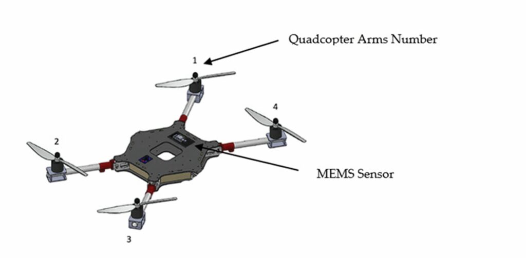
Rotor imbalance in quadrotor UAVs in particular poses a critical challenge, compromising flight stability, increasing maintenance demands and reducing overall operational efficiency. Traditional vibration analysis methods, such as the fast Fourier transform and wavelet analysis, often struggle with non-stationary signals and real-time data processing, limiting their effectiveness under dynamic UAV operating conditions.
One of the key challenges in UAV maintenance is addressing rotor imbalances caused by misalignment, structural wear or damage. These imbalances generate abnormal vibration patterns, compromising flight stability, increasing maintenance needs and reducing overall operational effectiveness.
Neural networks
Machine learning techniques such as multi-layer perceptron (MLP) neural networks can be used to analyse vibration data and detect anomalies in real time, even in the presence of noise and dynamic operating conditions.
Unlike convolutional neural networks (CNNs), which are optimised for image and spatial data, or recurrent neural networks suitable for sequential data processing, MLPs are highly effective at analysing non-sequential data such as vibration signals. Their inherent simplicity and adaptability make MLPs a suitable choice for capturing the complex, non-linear relationships present in UAV rotor imbalance scenarios in performance monitoring. The lower computational requirements make them suitable for real-time onboard implementation in resource-constrained UAV systems.
(Image courtesy of Putra University)
The MLP system uses micromachined micro-electromechanical systems (MEMS) sensors such as accelerometers for vibration data acquisition, preprocessing techniques for noise reduction and feature extraction, and an optimised MLP architecture tailored to high-dimensional vibration data.
Rotor imbalances typically generate vibrations in the range of 10-100 Hz, which fall comfortably within the accelerometer’s range of up to 260 Hz.
This ensures that the sensor can detect the primary vibration signals, the fundamental frequencies and their harmonics. The sensor’s range also supports capture of transient vibrations during rotor startup, shutdown or rapid speed changes, as well as steady-state vibrations during sustained flight. The upper limit of 260 Hz aids the detection of higher-order vibrations and harmonics that might arise from structural resonances or aerodynamics.
MLPs also excel in scenarios with small- to medium-sized datasets, a common challenge in UAV rotor imbalance detection where extensive real-world data collection can be difficult. Their relatively straightforward and customisable structure also makes them more interpretable than more complex counterparts such as long short-term memory models or hybrid approaches, thereby enabling easier debugging.
On a dataset of 800 samples representing both balanced and imbalanced rotor conditions, an optimised MLP model with five layers achieved a root mean squared error of 0.1414 Hz and a correlation coefficient of 0.9224 on the test dataset, demonstrating high accuracy and reliability.
For a model customised for UAV applications, the framework addresses challenges such as non-stationary signals, dynamic flight conditions and real-time performance requirements. This bridges the gap between traditional analytical methods and machine learning-based diagnostics for improved UAV safety and maintenance efficiency, and provides a scalable and effective solution for rotor imbalance detection in dynamic environments.
While hybrid models or CNN-based architectures might achieve slightly higher accuracy, they often come with increased complexity and computational overheads. Thus, MLPs strike a balance between performance and simplicity, making them a practical choice for rapid deployment and efficient operation.
Motor monitoring
The high risk of failure of bearings means that the identification and characterisation of bearing faults in motors via non-destructive evaluation methods have been studied extensively, amongst which vibration analysis has been found to be a promising technique for early diagnosis of anomalies.
For smaller UAVs that cannot accommodate MEMS sensors, a systematic approach is needed for in-flight non-destructive evaluation and health monitoring to enable efficient and safe operations in low-altitude airspace, as well as to mitigate associated risks to people and property on the ground.

Data might be vehicle-specific such as battery state of charge (SoC; a component health status), from third-party sources such as weather, obstacle and terrain information providers, or from UAV Traffic Management such as real-time traffic within an airspace.
Bearings
Current practice for ensuring the safety of a motor includes a prescribed pre-flight and post-flight inspection of the motors followed by replacement of the bearing parts if a motor is deemed to be warmer or noisier than its counterparts.
Bearings, like any component undergoing fatigue, are not supposed to fail instantaneously during a short flight of one to two hours, but lack of in-flight monitoring and the highly subjective nature of the prescribed checks occasionally lead to unprecedented motor failures. Besides intrinsic fatigue failure, environmental elements such as moisture or grains of sand caught in between the rotor and the stator inside a motor might affect its motion and aggravate a previously undetected fault.
Common practice at the time of writing is to assume periodic replacement of parts in lieu of condition based-maintenance.
In most commercial small UAVs, especially rotor-type vehicles, accelerometers cannot be attached onto each motor owing to weight and space constraints. This is the main reason for the gap in existing research and practical implementation of bearing fault diagnostics in small UAVs.
Most UAVs are equipped with a single Inertial Measurement Unit (IMU), which consists of a tri-axial accelerometer attached onto the main frame of the vehicle. A fault signal from the IMU is often buried within noise from other sources, such as external turbulence and propeller imbalances.
However, such IMU data can be used to identify vibrational disturbances experienced by the UAV that might arise from a faulty motor. It is imperative to detect vibrational anomalies during a UAV flight owing to the risk posed to UAV circuitry or the payload when exposed to abnormal vibrations.
It is difficult to detect vibrational anomalies in UAV motors using existing sensors from commercial suppliers without having prior information on the motor’s state of health at the beginning of the flight.
Tests with a DJI S1000 octocopter, the Pixhawk autopilot hardware and Ardupilot software used an existing IMU in the centre of the UAV with a 25 Hz filter to catch the vibrations that originated from the motors.
Comparison of bearing fault diagnosis methods on a laboratory dataset and from flight experiments on commercial UAVs has led to the development of a vibration anomaly indicator (VAI). The VAI was defined based on counting the non-unique frequency components in the feature space of UAV vibration data. Although the health indicator was demonstrated on flights with deliberately faulty bearings, one of the challenges of the proposed method is that the VAI can detect an anomaly but not isolate its source.
Data from the central IMU contains other information inherent to the vehicle, and the data from other sensors such as temperature or current measurements should be used in addition to the IMU information to refine the diagnostic results and identify the motor or bearing that failed.
To improve accuracy, the physics of bearing failures and degradation with the IMU measurement data needs to be integrated into the software for in-flight performance monitoring.
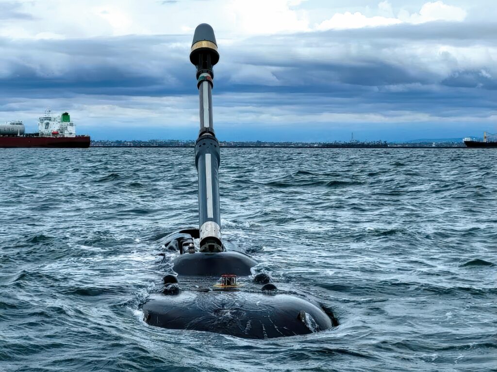
Underwater
Performance monitoring in UUVs, which include ROVs and AUVs, is crucial for vehicle longevity and data integrity. The harsh and unpredictable underwater environment presents unique challenges, making robust monitoring essential.
There are several areas where the system health of UUVs needs to be monitored. The battery capacity and the SoC are critical for endurance and mission planning, especially for AUVs, and monitoring the voltage, current and power consumption can identify anomalies, optimise energy usage and detect component failures such as motor strain. Of course, monitoring the temperature can identify overheating in the batteries, motor or electronic subsystems that can lead to critical failures.
Similarly, the condition of propulsion systems demands vigilance because thruster rpm and motor efficiency directly influence the speed and manoeuvrability of the vehicle.
(Image courtesy of the US Naval Postgraduate School)
The dive and buoyancy systems of UUVs are equally critical, acting as the lungs of the vehicle as it ascends and descends. To maintain stability and prevent erratic movement, the ballast tanks have to be balanced, the pumps and valves should be operational and depth control must be precise. Structural integrity, too, cannot be overlooked. From leak detection to vibration analysis, these measures safeguard both the hull from breaches and the machinery from fatigue.
Navigation and localisation emerge as another cornerstone of performance. UUVs rely on an ensemble of systems to chart their path underwater – GPS provides surface positioning, while an inertial navigation system (INS) can handle the submerged journey. Developers must account for INS drift rates and acoustic navigation signals, ensuring that the vehicle maintains an accurate sense of position. Doppler Velocity Logs offer precise velocity readings over the seabed, bolstering navigation, while roll, pitch, yaw and heading metrics ensure stability and accurate trajectory.
Communication systems, often the lifeline between operators and UUVs, present their own challenges. Engineers monitor bit-error rates, signal-to-noise ratios and bandwidth to ensure effective data transmission. Latency and link stability are constantly under scrutiny to prevent interruptions. Whether through acoustic or optical signals, robust communication systems are essential for transferring telemetry and maintaining control.
The payload and sensor systems require calibration checks and ongoing monitoring of data integrity. Proper management of storage capacity and active payload systems guarantees that no critical data or operational capabilities are lost during missions.
Effective performance monitoring can be realised by combining real-time telemetry data with onboard logging systems. Anomaly detection algorithms flag unusual and unexpected data while fault detection, isolation and recovery systems provide automated solutions, ensuring that even when problems arise, the mission can continue or the vehicle can safely return.
Large UUV monitoring
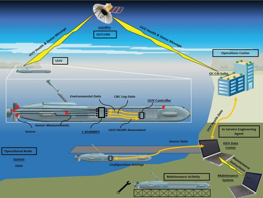
The introduction of large-displacement and extra-large UUVs with increased endurance on the order of weeks to months is driving the need for higher levels of reliability and consequently more performance monitoring. This is driving a Condition-Based UUV Maintenance Monitoring and Prediction System (C-BUMMPS) architecture with onboard sensing, monitoring and processing elements, in addition to onshore testing, data analytics and maintenance activities.
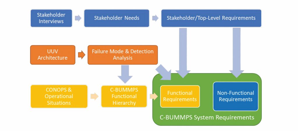
This uses a model-based systems engineering approach where the requirements of the analysis process were drawn from three distinct efforts. First was the stakeholder analysis, conducted to elicit the stakeholder needs and then translate them into requirements. These yielded both functional and non-functional requirements for the C-BUMMPS architecture. Next, the system operations were refined through further development of the operational situations, yielding C-BUMMPS functions that must be performed to support the operational activities. Finally, a generic UUV physical architecture was developed and underwent failure mode and detection analysis. This yielded additional functional requirements for how the C-BUMMPS might detect failures.
As well as vibration analysis, the monitoring architecture covers temperature measurements – using infrared cameras where temperature sensors are not viable – together with acoustic and ultrasonic monitoring, oil analysis, and voltage and current measurements.
A generic UUV physical hierarchy that can be adapted according to the specific needs and requirements of a UUV is a better approach than deriving a hierarchy for a specific UUV class, and this generic UUV physical hierarchy was derived from the Unmanned Maritime System. However, there is a challenge in using generic architecture developed for large and extra-large UUVs with the smaller Class C craft that might not have the space or resources to implement condition monitoring.
(Image courtesy of the US Naval Postgraduate School)
At the same time, the UUV condition-based maintenance system needs to use data from across all classes of craft to take advantage of common components and to correlate performance, degradation and failure modes across similar subsystems. The data can also be used to project estimated life cycles of components and subsystems to budget for spares and maintenance.
The developed architecture consists of onboard sensing, monitoring and processing elements on the UUV, in addition to the onshore testing, data analytics and maintenance activities required to support the maturation of the C-BUMMPS.
Performance monitoring of UUV components can assist with the mission, giving a probability of success should components start to fail.
Digital twin
On return of the UUV to port after a mission, the raw data and health assessments can be downloaded to a data centre and added to the life cycle performance profiles for the UUV subsystems and components. Analysis of the data will identify any trending deviations over time that might indicate wear or subtle degradation. Additional maintenance activities could be recommended or planned for future availabilities based on performance data that indicate a growing issue that did not exceed the threshold for generating alert messages during the mission.
Following maintenance activities, post-maintenance testing of repaired and replaced components is performed. The C-BUMMPS also collects performance data to verify that maintenance activities were successful and did not introduce additional problems. These data can then be used to either recalibrate the life cycle performance profiles or create a new baseline performance profile for replaced elements.
The data can also be used to create and update a digital twin of the UUV, modelling the system in the data centre while the physical version is out at sea for months at a time. This can be a way to provide data on smaller craft without the detailed sensor networks.
However, there are key factors that have to be identified as part of the UUV performance monitoring architecture. For example, measuring the rotational speed of a motor once every minute might be insufficient as a performance monitoring parameter. However, measuring or sampling rotational speed at 100 kHz for a motor that operates in the range of 103 rpm might produce an excessive amount of data for that performance parameter, driving the sensors and data acquisition, storage and analysis far beyond what is useful, let alone necessary.
Acknowledgements
With thanks to Julio Memba at UAV Navigation-Grupo Oesía, Ba Tarfi Salem Abdullah Salem at Putra University, Malaysia, Portia Banerjee at NASA Ames Research Center, California, and Dana Colegrove at the Naval Postgraduate School in Monterey, California.
UPCOMING EVENTS


