


Motor controllers
(Image courtesy of Hargrave)
Switching it up
Rory Jackson looks into the latest practices, components and advancements that are making for long-lasting, trustworthy and regulations-compliant motor controllers
Until around ten years ago, manufacturers of electric drones were generally stuck with using hobby-grade ESCs (electronic speed controllers) for control of their electric motors. Such low-quality components frequently suffered from issues such as poor transient response and low power density, and rarely lasted more than 50 hours.
Within the last ten years however, advancements in technologies for electric vehicles (EVs) and the increasing rate of hybridization among UAV engine companies have given rise to new motor controller products and design topologies well-suited to the tens or hundreds of kilowatts needed by vast heavy-lifting UAVs and autonomous air taxis.
Meanwhile, for smaller UAVs and robotic vehicles, there are new well-engineered ESCs suitable for military and industrial applications, with highly precise and efficient motor control, and longer lifespans to ease maintenance costs and duties on operators.
Both of these uncrewed vehicle types and more can now be served by increased tendencies towards ease-of-use, cost-effectiveness, and functional safety that the high-end motor controller manufacturers of today have taken to heart, in their determination to share in the rapidly-growing world of autonomous, electrified vehicles. A number of innovations and best practices are key to how they are achieving these properties, both at a high level and within the ecosystem of hardware and software components that comprise a working motor controller.
Reliable components
As certifiability becomes prioritised across the majority of UAV (and other uncrewed vehicle) development projects, and UAVs increasingly fly near or even over populated areas (making redundancy in powertrain components vital for getting flight permissions), so has reliability become the defining characteristic that motor controller developers aim for most prominently, from R&D through to production. When it comes to engineering new products, the fight for reliability starts at the high level architectures of different controller designs, before filtering down into the board-level components.

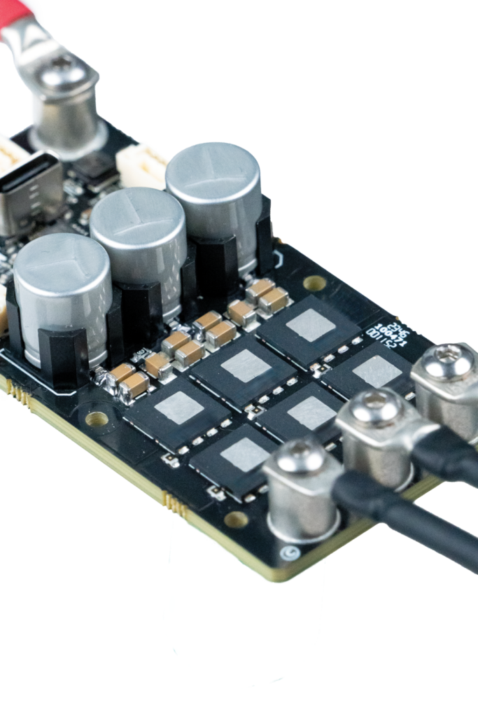
As a general rule, achieving a holistic integration in which all the components on the board work well together will take an ESC far, as will selection of efficient and long-lasting components. This can mean high-end silicon MOSFETs and low-impedance capacitors, for instance. Beyond that, one architectural approach which has proven effective has been to use over-specced components with current and thermal operating limits considerably higher than expected operating requirements.
While that might not sound inherently efficient, given that right-sizing seems to be the name of the game in so many electric and autonomous vehicle projects, one of the leading reasons why hobby-grade ESCs fail to live up to UAVs’ reliability requirements is that they run on parts whose limits run extremely close to where their platforms operate. When no headroom is left for current or heat spikes among the MOSFETs, capacitors and elsewhere, critical failure is likely to follow in short order.
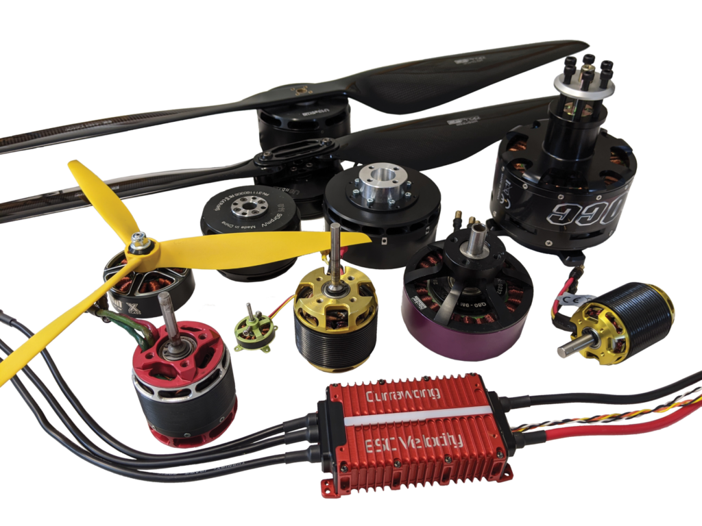
(Image courtesy of Currawong)
Another approach has been to separate hardware and firmware into independently modular and optimisable systems through a chiplet-focused motor control board architecture. Discussed in detail in our last investigation of embedded computing systems (see issue 59), chiplets are, in essence, highly size-optimised devices resembling system-on-chip products that subsume most (if not all) of the central processing functions on a PCB, with secondary and tertiary functions then distributed to other integrated circuits nearby.
In this approach, a chiplet featuring a microcontroller, numerous I/Os, and other components (and embedding one universally-applicable firmware platform) sits at the centre of an ESC’s layout, amid the capacitors, MOSFETs, gate drivers, terminals and so forth. Due to its plethora of I/Os and the one-size fits-all way its embedded logic is written, the way that chiplet interfaces with other ESC components is pre-defined for any bridge topology. Hence it can control small, 20 A drives, or a heavy 30 kW system, and anything between seamlessly.
This results in several key benefits; for one, lead times for customised motor controllers are considerably reduced (sometimes taking little more than a month), as firmware and central processors need not be created anew or even significantly modified for running a new, bespoke solution. That greatly accelerates product development cycles and makes the motor controller manufacturer more agile in fulfilling the needs of new uncrewed systems and their powertrains.
It also makes the firmware itself far easier to test, validate and improve upon, as new fixes or subroutines can be proven out in real-world conditions on small, inexpensive flight test aircraft. Even if unrepresentative of the intended recipient aircraft of a new software fix or add-on, the new functionalities can still be triggered on a smaller platform, with no significant loss if the test drone crashes due to an excessive thrust or overcorrection behaviour.
Chiplets for motor controllers are not, as of writing, topologically dissimilar from very small PCBs, or something available off-the-shelf just yet. Those we have seen are proprietary creations which took years of optimisation work on firmware, hardware stamping, SWaP, performance and reliability. For a motor controller manufacturer to produce such a system and hence an ESC architecture around it, takes considerable in-house resources for circuit board assembly and production. Additionally, copious testing hours – running into the hundreds of thousands on bench and aircraft – are vital to affirming that such a chiplet can be trusted as a universal core for different ESC and motor drive permutations.
And while high-end motor controllers today are reaching MTBFs of 4000 hours, matching the lengthiest lifespans of e-motors and UAVs in many cases, any further extensions to ESC operating lifetimes remain limited by the capacitors. As we reported in our previous investigation (see issue 35), capacitors are still the leading cause of failures on any motor controller, most often due to imperfect installations or selections.
The latter can especially occur when a distinct lack of quality control or validation testing has been carried out by the supplier, to affirm key characteristics such as capacitor ripple current (which most capacitor manufacturers don’t do). It can also happen when the capacitor has not been installed cleanly enough on the board. When these are not done, inevitably the ESCs are asked to perform beyond the capacitors’ operating window, potentially causing them to break after some tens of hours, or explode within seconds.
Modern ESC architectures designed for reliability will avoid this problem by first testing their supplied capacitors where necessary, and then integrating enough capacitors inside or on the PCB such that the vehicle manufacturer does not need to hand-solder their own capacitor banks onto the boards. This helps scalability on the OEM’s end, skipping the need for laborious and potentially inconsistent or unsafe board mounting processes.
Such is the inconsistency that can happen when capacitor installation is left to the uncrewed vehicle manufacturer, that safe input lead lengths are limited to 12 cm as a result. Naturally, this can be heavily restricting for any OEMs who may want a larger UAV than 12 cm cables permit, especially if using VTOL drive modules whose dimensions far exceed 12 cm (a common sight for heavy-lift applications).
Controlling capacitor installation in-house, by contrast, enables input leads of 3 m lengths, and saves UAV engineers and technicians from needing to solder anything. The resulting ESC may be slightly larger than those which ship without their capacitors integrated, but saving the end-integrator from soldering, verifying solder joints, or redesigning their UAVs’ drive architectures to accommodate the ESC and its cabling is invaluable.
(Image courtesy of Embention)
And though most ESC manufacturers continue to get good reliability and lifespan from using electrolytic capacitors and ceramic capacitors for their bulk capacitance, some ESCs now come with hybrid polymer capacitors, which may provide extra vibration and shock resilience over the other types. However, integrating high numbers of small ceramic capacitors greatly reduces the individual inertia (and hence shock and vibration concerns) of each, as well as spreading electrical and thermal loads broadly among them, making for an efficient design strategy.
Electrolytic capacitors, by contrast, tend to remain disadvantageous in these respects even when installed and arranged creatively, and may still need to be replaced on the customer’s end, unlike their ceramic and hybrid polymer counterparts.
SiC
Across the EV world, silicon carbide (SiC) power transistors are becoming widespread, not only for their great efficiency in high voltage, high speed switching, but also for how much more available they have become over the past five years.

Notably, however, SiC has not quite proliferated among UAV ESCs, with some manufacturers having moved away from them due to a number of reasons. For one, despite the higher quantities supplied, SiC MOSFETs remain pricey: often 10-20 times the price of high-end silicon FETs. Additionally, UAVs today rarely operate at the 800 V levels that bring out the real efficiency advantages of SiC; for 60-120 V UAVs, SiC adds a lot of cost, to not very much benefit.
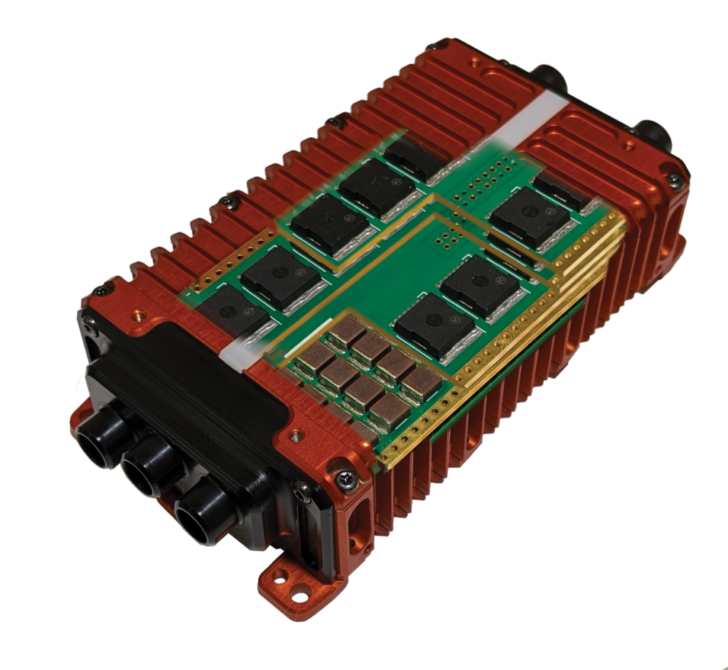
But the keyword there is “rarely”. Some very large motor controllers have been recently engineered and made available to suit both very large, very heavy-lifting UAVs as well as urban air taxi-type eVTOL aircraft (UAM). For these, 800 V architectures are necessitated by the hundreds of kilograms and hence hefty amounts of current (up to or exceeding 200 A per ESC) to be pulled in such applications.
Motor controllers in this category are being engineered for compliance with DO-178 and DO-254 standards (which respectively detail software and hardware airworthiness requirements), a vital aid in UAV and UAM certifiability. One can also find SiC transistors within their architectures. While silicon IGBTs
remain the most common choice among 800 V inverter and motor controller devices, the proliferation and improvement of SiC MOSFETs (as well as peripherals for enabling SiC-based bridge circuits) has furthered SiC’s efficiency advantages. Rising commercial availability has also made SiC less expensive to acquire, reducing the cost barrier of switching from IGBTs to SiC.
(Image courtesy of Currawong)
Size optimisation of 800 V motor controllers typically requires multiple boards inside such devices – at the very least, one board for hosting the power management components and another for the control and intelligence components – which can be stacked atop one another to prevent a cumbersomely wide solution. However, between SiC MOSFETs and IGBTs of equivalent power throughput, one often finds the SiC to be the smaller of the two. That, combined with SiC’s much greater thermal efficiency (reducing the size and weight of any cooling mediums they may need) means that SiC inherently makes for smaller and lighter motor controllers. One can expect to see a significant re-growth of SiC-based devices over the next 10-15 years as a greater proportion of uncrewed vehicles come with high voltage electric and hybrid drivetrains in need of less heavy, costly, and thermally burdensome DC/AC and DC/DC components.
Firmware practices
While ESC firmware is accessible and available online, such as BLHeli_S, Bluejay, and AM32, high-end manufacturers increasingly insist upon the necessity of engineering their own firmware in-house, from the ground-up. The prime reason given is that the incredibly high switching speeds of UAV motor controllers mandate an extremely tight, holistic integration between software and hardware, particularly as UAVs increasingly start to move hundreds of kilowatts with nanosecond-scale switching intervals.
Without that matching between software and hardware, the software may make demands either in excess – or falling short – of the hardware’s capabilities, potentially resulting in inefficiencies and latencies in operation, and hence insufficient switching speeds for the kinds of throttle response or vibration minimisation expected of today’s industrial UAVs. Alternately, the software might fail to account for correct slew rates – how much voltage or current gets changed per unit of time – by not sensing or responding to inputs accurately. In extreme cases, such a mismatch could trigger a fault so severe that the ESC overloads its capacitors and explodes mid-flight.
Making one’s own firmware helps avoid these issues, and also minimises the chances that sporadic new protectionism barriers will not suddenly cut-off one’s access to ESC firmware simply because it came from a targeted overseas country. On top of those, it enables masses of testing data (and also possibly user data) to start informing the modelling of empirical analytics functions highly useful to end-users, such as AI detection of capacitor failures, motor saturations, and other drive errors.
Those can then be plugged into customers’ GCSs, to record the errors in their flight logs, or flagged in their GCS interfaces in real-time as alerts or recommendations to abort flight and bring down the aircraft. With such capabilities potentially enhanced via the integration of sensors for real-time overvoltage, overcurrent, temperature and so on (particularly when installed across different sections of the board to pinpoint the exact location and cause of an electrical or thermal issue). And while high-end motor controllers and drives will experience such failures rarely over their 3000-4000 hour lifespans, such capabilities can be invaluable when building a safety case to be submitted for gaining flight approvals.
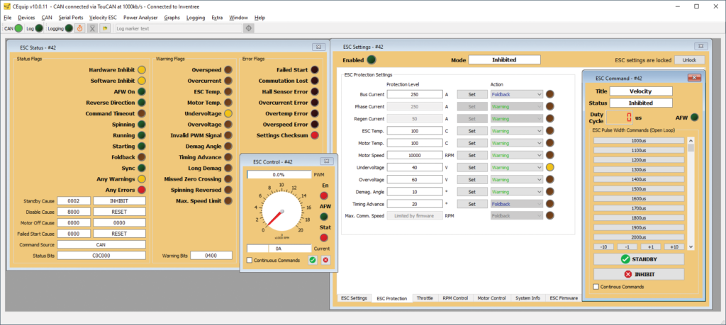
Naturally, transmitting ESC and motor telemetry, as well as error messages, depends heavily on using effective communications protocols. Newer generations of motor controllers now widely use DroneCAN (formerly UAV-CAN). DroneCAN enables extended telemetry and communication of diverse information sets for analysing (and thus optimising) drive safety and performance, not just in motor drives but also in servos and autopilots. With proliferation of the protocol in those other components of course making the transition more sensible and appealing for ESC manufacturers, thanks to the greater compatibility and hence adoption it creates among UAV subsystems.
High-end manufacturers will also supply ESCs with other advanced, modern protocols, such as ARINC-825 CAN, which is more common in military applications. Like DroneCAN, ARINC-825 networks enable multiple subsystems to communicate quickly and efficiently over a single bus with low latency, allowing real-time control and monitoring of control surfaces, engine throttle, and e-motor drives.
Furthermore, it has – again, like DroneCAN – been designed for decisive fault detection and isolation in its networks, as well as message prioritisation and ad hoc, over the air firmware scaling and updating – all more proficiently extent than the conventional CAN 2.0b.
That ability to update networks and firmware modules as needed, via having a comms protocol structured to do so, saves copious time on having to redesign or reconfigure vehicles’ networks to accept such updates. It is imperative, however, that customers use their own flight controllers to define even the most plug-and-play ESCs within their networks, connecting and flashing them to particular configurations individually, as that ensures updates and reconfigurations are deployed from a central hub within the software architecture, minimising room for error and hence faults.
Thermal management
Ensuring robust thermal management is paramount to the reliability and service life of motor controllers, as the biggest limiting factor on motor controllers today is how much power can transmit through without being lost as heat. Maximising that takes scrutiny of every square inch of board space, starting with one’s MOSFETs and the thermal aspects of their design.
Among the MOSFETs commercially available today are some that come with proprietary metallic surface materials, which can then be coupled with thermal management approaches on the part of the ESC manufacturer, such as having plates of copper or gold installed on the opposite side from where their MOSFETs sit, ensuring an effective cooling surface to extract heat through the PCB from the FETs’ undersides.
This makes for a dual-cooled transistor topology which can be highly beneficial at any product size and power throughput, regardless of whether the housed ESC is placed under a propeller’s downwash, inside a fuselage, or force-cooled by ram air, fans, or pumped water-glycol. At day’s end, heat will accumulate at the MOSFETs and baffle their performance without defined, incisive thermal interfaces at ground zero.
With that, customers can place a thermal pad directly against or under the MOSFETs, creating a direct conduit for heat to pass out of the semiconductors and into their external heat sink, particularly if pads and enclosures can be customised by the manufacturer to fit the end-integrator’s available packaging volume or mounting spot. High copper infill inside of PCBs also helps maximise the number of pathways for heat to be conducted out of the motor controller, as well as enabling larger conduction paths with reduced resistance throughout the board.
However, one alternative path to customising the enclosure has also been to leave a somewhat open space adjacent to the motor controller board, to enable customers to bond whichever type of heat sink suits the thermal profile of their application best, whether that be a finned air-cooling sink or a liquid-cooling plate with serpentine channels snaking throughout. As one might expect, this approach has been motivated by a rising number of OEMs who specifically aimed to design and construct their own, highly optimised thermal sink.
Commutation
The trajectory of motor controller design evolution five years ago seemed to suggest that field-oriented control (FOC) was going to become universal across high-end units. That hasn’t happened, however, for a few key reasons. One is that, in many cases, FOC-based ESCs remain slightly expensive due in part to processor requirements; though this can be offset when coupled with sensorless BLDC motors.
Additionally, effective FOC depends on wave shaping of the input AC current in order to keep a high power factor. But when the commutation frequency runs close to the switching frequency due to very high motor rpms, the ability to wave shape depends on having many switches per commutation instance. Hence for high-speed, highly dynamic applications, effective FOC motor controllers may actually need to be far larger than one hopes for maintaining good control response at the limits.
Furthermore, while FOC can provide very smooth, high-fidelity control, achieving that in field operations can be challenging without painstaking efforts to tune the algorithm and controller exactly to how they will be run in practice (and indeed, many UAV manufacturers lack the facilities to do so appropriately). As an example, most manufacturers will tune the FOC algorithm at room temperature conditions, only to fly their UAVs in either significantly more heat, less heat, higher moisture, lower moisture, and so on.
(Image courtesy of Hargrave)
Alternatively, there may be manufacturing variations in the motor, propeller, or wiring harnesses which are hard to account for in the tuning process, or the operator may simply push the ESC so hard that it exudes and accumulates an inhospitable environment around itself.
These variables could affect the efficiency with which power is transmitted, or with which rotors climb through air, and many other factors, especially given that uncrewed systems increasingly work in harsh and dynamic environments which deviate wildly from the single point of collective operating conditions at which the motor control is typically tuned.
As a result, some very high-end ESCs are still engineered for trapezoidal commutation. It is important to note that trapezoidal control can enable much greater power density, a critical requirement for eVTOL UAVs which need to spool four or more e-motors up or down simultaneously at key moments in flight. It also tends to be significantly less expensive than FOC, and does not suffer from the wave shaping issue at high rpms (nor some other edge case nuances).
Another alternative route has been to develop new algorithmic approaches, one of which has aimed to produce a version of FOC which can tune itself in real-time, maximising efficiency gains across a wider range of external conditions. This may mean an algorithm which fails to match FOC’s absolute peak performance outputs to the fractions of a percent in controlled lab conditions, but otherwise gains 3-5% power efficiency over each real-world UAV flight. For organisations flying hundreds of hours per year, that could mean considerable improvements in energy or fuel bills.
Creating such a commutation algorithm does not require AI training – many still argue (correctly) that AI has no place in actual direct motor control, and must be limited to observation-based analytics of ESCs. Instead, traditional programming rigour remains the best tool for the job, with clear drive responses to every input defined by human programmers, taking account for how environmental variations can affect motor and ESC performance, such that the commutation algorithm can switch modes and maps to compensate in an apt manner.
Manufacturing and testing
With motor controllers now being manufactured in large batches for long-term uncrewed vehicle manufacturing contracts, ESC producers are honing their best practices for an efficient and transparent production floor. Often, that begins with a close consultation between engineering and production personnel – if done right, the former will make sure to design something manufacturable, and the latter will understand what to configure for in both production machinery and quality control checks.
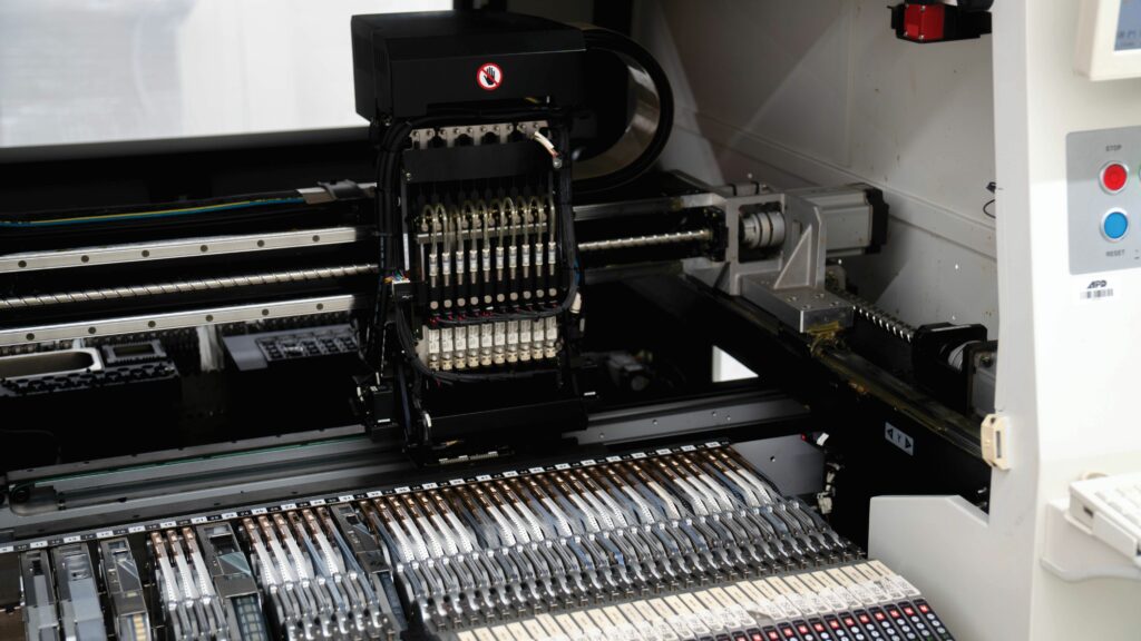
With new, more advanced motor control boards featuring higher quantities of copper and gold, standard pick-and-place machines will not cope well unless revamped significantly to account for the heat transmission requirements of boards with higher than typical metallic infills. Producing such PCBs means getting more heat into the boards, in order to ensure solder materials can reflow correctly, which can be challenging given that such advanced boards are designed layer by layer to inherently wick heat away as quickly as possible.
(Image courtesy of Currawong)
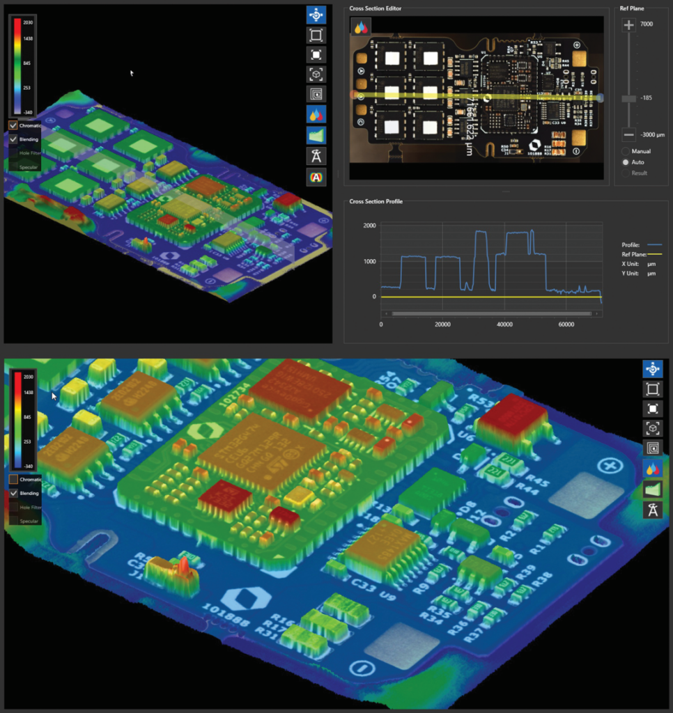
Quality control approaches are being stepped up also, with growing use of 3D optical inspection machines, constructed of six or so cameras on gantries, and using both their optics and different light projections to produce granularly detailed measurements, as fine as 6 microns (0.006 mm) in some cases. While this can mean generating up to 2 GB of 3D model data per inspected ESC board, and could hence merit considerable overhauls of manufacturers’ data extraction and storage facilities, the validation entailed is a critical addition to existing human analysts. Every component and solder joint is being precisely evaluated for correct position, orientation, flatness and other parameters, to a level of fidelity beyond human ocular patdowns, and potentially against a pre-existing ‘gold standard’ motor controller product for extra certainty.
That level of precision can also be useful in automating traceability measures. Serial codes, QR codes and so on can be autonomously tracked and read not only by colour patterns but also by the depth of engravings and inks present. That ensures any failure in any one sub-component of a given motor controller can be traced back to its 3D model, its supplier, its journey through the factory, and its end-of-line tests to pinpoint why any fault or even slight performance shortfall might have happened from a production standpoint.
(Image courtesy of Hargrave)
End-of-line tests are particularly stringent, given the safety-critical nature of ESCs. These can particularly consist of installing each motor controller and using it to spool up an e-motor, then recording and checking the results.
Future
Given the rate of competition in both autonomous and electrified vehicles, motor controllers in the uncrewed world are well-placed to benefit from a host of advancements across academia and OEM research labs aimed at driving advancements at the molecular level for every key component they use.
Many of these are likely to concern thermal management, which has been cited to us as the most untapped of low-hanging fruit in EV engineering. Not only are many propositions for advanced board components and heat mitigation methods coming forth today, but means of sensing or predicting hotspots in different components are also being found. Similarly, means for detection and mitigation of other issues such as switching oscillations or harmful resonances are being found, and could transmute through to commercial application before long.
Such discoveries lend credence to the idea of a highly data- and analytics-driven future in uncrewed systems; as owning fleets of autonomous aircraft, boats and other vehicles becomes standard throughout industry. Squeezing maintenance costs and inventory turnovers will become a dogged pursuit of many companies, especially as new high voltage systems may go through initial teething phases when first applied in real-world conditions. Lessons from the EV world, combined with the considerable innovative capacity inherent to the uncrewed world, will be vital to continued development and proliferation of effective and reliable motor controllers in the years ahead.
Acknowledgements
The author would like to thank Saami Bashar and Felix Schulz from Hargrave Technologies, Javier Espuch from Embention, and Gavin Brett and Oliver Walters at Currawong Engineering for their help in researching this article.
UPCOMING EVENTS


