


Power management
Nick Flaherty examines the factors driving the need for new power management architectures and the improvements they promise
Better by design
Power management is all about efficiency. At current levels of efficiency, incremental improvements in power system design of just 0.5% can cut losses by 20-30% with associated reductions in size and weight.
For UAVs this means longer range, while for driverless cars it addresses issues of the power consumption of the sensors and processing devices. The latest Lidar sensors for example use gallium nitride drivers that need more sophisticated power management, while the move to centralised processing with high-performance AI accelerators requires management of large currents.
All of this is driving new architectures, from intelligent power modules (IPMs) for driving motors to distributed power conversion with soft switching and different levels of power regulation. Meanwhile, solar power is being used for fixed-wing UAVs, which is leading to the development of new algorithms to track the optimum power point for maximum efficiency.
However, many rotor-based aircraft cannot easily take advantage of solar panels, so designers have been looking at other energy sources such as fuel cells. These need a different power management architecture to combine battery and fuel cell energy sources.
UAVs
Actuation systems are migrating from traditional hydraulics to electric. This is driving the adoption of distributed power management architectures for primary and secondary flight controls, landing systems and vector control for directional thrust.
These power systems need three-phase motor control, solenoids that hold flight control surfaces, DC bus voltage regeneration and soft starter controls to limit the inrush current. This requires more IPMs with more intelligence.
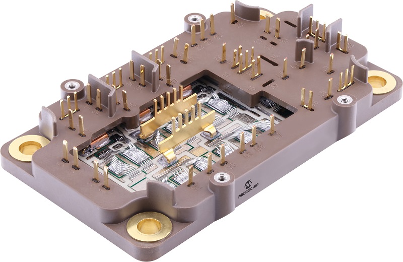
The latest hybrid power drive modules combine four power switches, a controller and a thermistor into a single package weighing 150 g and measuring 108 x 67 x 27 mm. The modules support voltages from 5 to 15 kV as standard using a silicon carbide (SiC) MOSFET transistor and a diode or a hybrid approach with a silicon IGBT power transistor and an SiC diode.
SiC has better behaviour for a given power density than silicon IGBT devices. This reduces the overall junction temperature and gives a 1-2 percentage point efficiency boost. It also boosts battery life significantly.
The modules use a silicon nitride (SiN) substrate for better stability and reliability than aluminium nitride. SiN provides enhanced bending strength, fracture toughness and thermal conductivity.
The modules can be attached to the substrate with high-temperature solder or pressure silver sintering. The sintering process starts with treating the die with a silver layer a few tens of microns thick. A pressure of 1-10 MPa and a temperature of 250 oC is then applied to attach the die. This provides a better thermal interface than soldering.
The modules can be supplied with or without a baseplate. The heat generated in the modules can be hundreds of watts so they need to be mounted on a heat sink or to a metal part of the airframe.
Power architecture
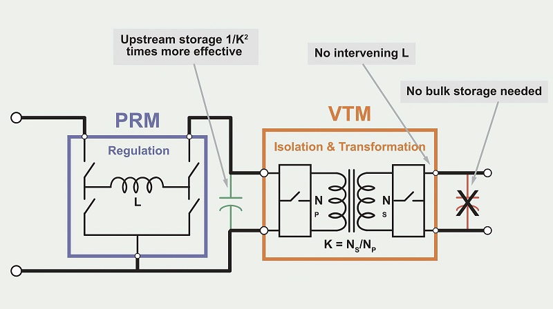
Another power architecture splits the functionality of the DC-DC converter into the isolation and step-down function, and the regulation of the voltage.
With this architecture, a Pre Regulation Module (PRM) supports a wide input range to a voltage that is close to the optimal point that gives the best conversion efficiency. Compared to a hard-switched, multi-phase topology, the zero-voltage switching (ZVS) and zero-current switching (ZCS) topology, running at the highest practical frequency, is more space-efficient and dissipates less power.
A ZVS and ZCS topology does not have the high-frequency, harmonic-series noise profile character that occurs with a hard switching topology. With an operating frequency above 1 MHz, the architecture avoids the 100-500 kHz frequency content that interferes with radio systems and other components.
This low harmonic content and high fundamental conversion frequency means the noise filter is smaller, and engineers can create low common and differential-mode (CM and DM) noise designs, particularly when component arrangements and device interconnects are properly considered.
As always, input and output filters are required and must be designed and placed properly, but the inherent nature of the architecture make this task easier.
As an example, a power delivery network (PDN) for a converter with a 28 V input at 300 W is converted using an isolated, regulated DC converter. The low profile of the thermally efficient module enables a cooling solution using an available cold wall and leads to a 818 W/cu in power density that reduces the PDN’s footprint.
Solar power
Gallium arsenide solar modules are popular for UAV operation, as they provide high efficiency conversion with low weight, but they need sophisticated power management to provide the highest levels of efficiency.
The mathematical behaviour required to calculate the electrical energy production from solar energy on a UAV from known UAV angles of rotation, the position of the sun in the sky, solar irradiance measurements, the solar module area and the solar modules efficiency has been integrated into a custom-made maximum power point tracker (MPPT) with an integrated perturb and observe (P&O) algorithm.
Aerial mapping mission flights show that the energy efficiency is more than 96.27% for the MPPT, which extends the flight time by up to 21.25%, showing the importance of power management.
The MPPT was installed on a Bramor UAV with a parallel connection between two, four-cell lithium polymer batteries as the primary source of electrical energy. Each battery had a nominal charge capacity of 11 Ah, an energy capacity of 162.8 Wh and a mass of 820 g. The parallel connection provided a total nominal charge capacity of 22 Ah, a total energy capacity of 325.6 Wh and a total mass of 1.64 kg. This amount of energy was enough for up to 3 hours of flight time in good weather.
The solar module was connected to the UAV battery via the MPPT. The tracker ensured that the maximum available electrical power was transferred from the solar modules to the battery under given conditions. The maximum power from the module can be obtained if the module works at the maximum power point (MPP).
There are many types of trackers with different MPP searching algorithms, although there are practically no off-the-shelf trackers intended for use on small UAVs.
The MPPT function can be performed in analogue, digital or most often digital-analogue mode, where the core component of the MPPT’s functionality is a microcontroller that manages the duty cycle of the DC-DC converter. Changes to the DC-DC cycle should be reflected in the different electrical power levels generated by the solar module, and the goal of changing it is to find the MPP.
The main task of the MPPT is to find the MPP rapidly, with less convergence time and less oscillation. Finding the MPP can be achieved via searching or calculation.
In such cases, an algorithm is run on a device intended to track the MPP. The efficiency of this type of MPPT depends on the algorithm’s efficiency as well as that of the efficiency of the hardware components. The algorithms differ mainly in the speed of tracking the MPP, the complexity of implementation and the type of sensors, whose measurements act as input data into the algorithm.
The algorithms are divided into direct and indirect. Direct algorithms require current and voltage measurements of the solar modules, meaning the determination of the MPP position is independent of non-electric quantities such as solar irradiation and temperature.
Indirect algorithms determine the position of the MPP by known non-electric quantities. They are more complex and expensive in terms of integration, and the most widespread indirect algorithms are P&O and incremental conductance.
Both are very effective under stationary conditions, although with faster changes in irradiance, their effectiveness can be lowered owing to the loss of the tracking direction. However, most algorithms introduce a certain loss under stationary conditions, which depends on the voltage oscillation around the MPP.
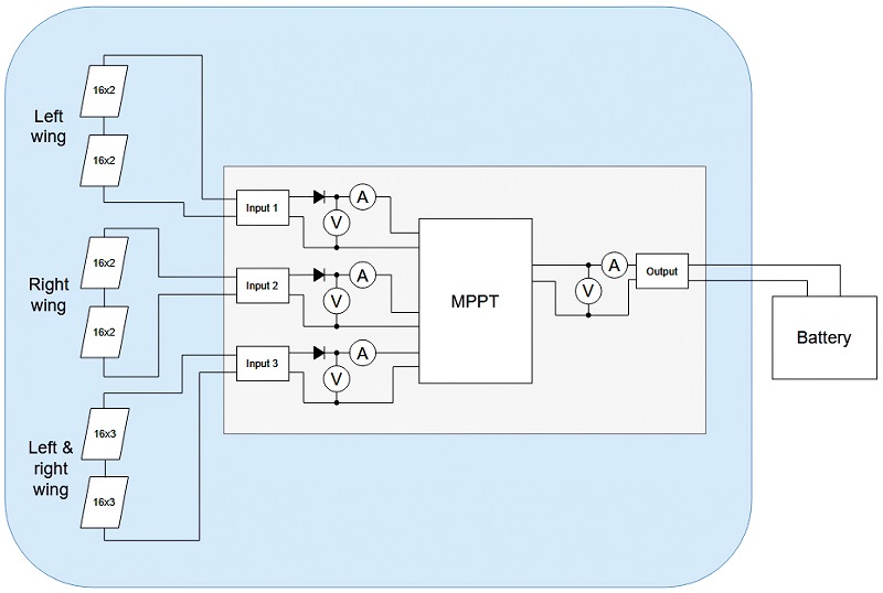
Each MPPT input line and output line involves current and voltage monitoring. This raises the possibility of monitoring the current and voltage to calculate the power on each chain with solar modules and the MPPT output during the flight. These measurements are performed using a current, voltage and power monitor.
A core component of the MPPT is a DC-DC buck-boost controller with a P&O-type MPPT algorithm. The controller tracks the MPP every 180 seconds, but if a new MPP with a higher yield is found, the controller starts tracking around the new point.
The buck–boost controller can provide a voltage above, equal or below the input voltage, and is appropriate for a range of input and output voltages up to a maximum of 80 V.
The internal analogue-digital (A/D) conversion value of the controller is 10 bits of resolution, although the A/D resolution of the pulse width modulation (PWM) signal needed to properly measure and modulate the input and output voltages is 8 bits.
The controller also includes a battery charging algorithm denoted as the constant current/constant voltage (CC/CV) algorithm, which is most widely used for lithium-ion and lithium polymer batteries. Battery charging is performed when the electrical energy production is higher than the power consumption of all the potential loads connected to the battery at the same time.
For a full battery voltage setpoint, 16.6 V is selected, which for safety reasons is 0.2 V lower than the value of a completely full battery.
All external components, such as inductors and transistors, must be assessed and chosen properly. The requirements depend on the known input/output current and voltage ratios on the basis of the chosen switching frequency, which is 202 kHz. This frequency is a compromise between the physical size of the inductor, the input/output capacitors on one side and switching losses on the other.
The buck–boost switcher logic requires four transistors. One pair handles switching in buck operation mode, the other handles switching in boost operation mode, and all four transistors handle switching when the output voltage is similar to the input voltage. Transitions between modes depend on the ratio between the controller’s input voltage, output voltage and switching frequency.
For two transistors, the main part of the power loss is caused by switching losses, while for the other two the main part of the power loss is caused by ohmic losses. It is therefore important to strike a compromise between transistor RDSon resistance and CRSS capacitance.
The chip monitoring the current and voltage communicates over an I2C bus, but an external device is needed to read these measurements during flight. A data logger captures all measurements at a frequency of 1 Hz and saves them on an onboard microSD card. The frequency source is provided by the external device.
A pulse per second (PPS) output signal with a very accurate UAV GNSS receiver has been used for this task. Precise knowledge of the frequency of the captured data allows these measurements to be combined with the UAV’s log data.
Multi-mode power
To extend the battery charge, aircraft range and operational capabilities of a UAV, power can be generated from multiple sources during flight, including solar power itself and wing structural vibration-induced power generation. These can be harnessed and used to power an electric motor and propeller propulsion system while the UAV is in flight.
Ultra-lightweight 3D-printed graphene supercapacitors can be used with the power management system, and the system will optimise power usage throughout the entire vehicle and storage of the excess electricity.
The main power management system draws power from three sources. One is the photovoltaic solar energy from the solar cells, while the second is the compressive strain energy harvested through the piezoelectric generators attached to the root of the wing where most bending strain occurs. Mechanical energy from sub-critical flutter in the airframe is harvested from a spring-motor/generator device as the third source mounted inside the UAV, where it will convert wing vibrations into electricity.
The power management system itself consists of six components – rectifiers, MPPT boards, balance boards, alarms, diodes and supercapacitors. The rectifiers allow the generated power to be fed into the system at an optimal level.
The MPPT board maximises battery life and power output while a separate balance board distributes energy evenly to the graphene supercapacitor, and diodes prevent negative current feedback into the generation devices. An alarm system is implemented to give an alert whenever the output voltage reaches a low level, because it could potentially harm the entire system.
The system can be scaled up to accommodate larger craft, reducing the need for heavy battery banks.
Fuel cell
Fuel cells can potentially deliver up to five times higher energy density than lithium polymer batteries, leading to a major increase in a UAV’s endurance. Beside fuel cells, a supercapacitor can contribute to the power supply process as well, as it offers a very high power density and fast response to the peak power required for take-off and sudden manoeuvres of UAVs.
A hybrid energy management system (EMS) can be used to balance the fuel cell, battery and supercapacitor power delivery. The EMS is designed to monitor the power dispatch between the onboard energy sources with voltage and current sensors to track the power flow, plus converters to monitor power source outputs, and has a processing unit that holds the adopted power management strategy.
In practical terms, fuel cells can achieve an efficiency of around 60%, which is not as efficient as lithium batteries, at more than 90%. Embedding a supercapacitor as a supplementary power source in a UAV’s hybrid power architecture boosts the power density and provides a faster power response though, both by delivering peak power and absorbing power fluctuations during dynamic flight with rapid changes in power load.
The EMS has to include critical constraints such as flight conditions, power requirements, dynamic power response, fuel consumption, battery overheating, state of health and state of charge monitoring and power distribution efficiency.
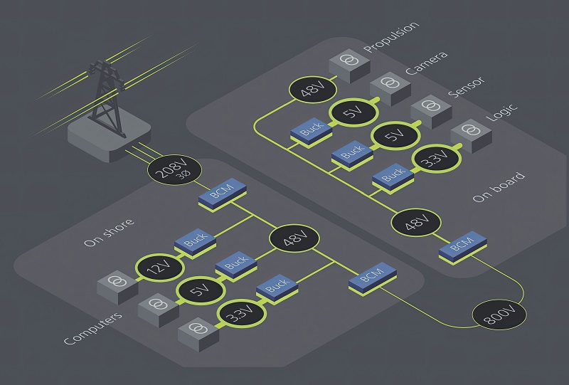
Tethered UASs
Some uncrewed vehicles are powered and controlled via a tether from a ground-based power source. Using voltages of 500 to 800 V allows for greater tether lengths, as the reduced losses allow smaller and lighter cabling, enabling a UAV to fly higher or an underwater vehicle to travel further.
The PDN inside the vehicle must be capable of converting the tether’s high-voltage power source with high efficiency, high power density and low weight in order to free up payload space.
A cabled, or tethered, UAV receives its primary power via a cable bundle from the ground. Control and telemetry can also be transmitted via the cable, or can be wireless like their battery-powered counterparts.
In a battery-powered UAV, the local battery discharge must be closely monitored by the vehicle. In contrast, in a UAS the tether-supplied DC power is typically very predictable and reliable.
The base station of the UAS is the power provider for the UAV. A manufacturer will want to build a system that will be able to work with different AC or DC power networks, supplying the tethered vehicle with a stable DC bus voltage. The system designer must consider countering disturbances or changes on the power line, as they could affect the UAV’s position in the air by changing the speed of the propeller and so changing the height of the craft.
Events such as load dumps and power transients are common while supporting the base station off-grid, for example from a ground vehicle or sea vessel. These events can also create disturbances or even interruptions in the power source for UAVs, so they often include an emergency battery to guarantee a controlled, powered descent from any altitude.
That means the UAV itself needs a power supply to regulate the tethered input power and handle the management of the onboard battery.
One of the challenges when designing a power supply for a UAV is choosing the most suitable voltage range. The designer has to decide between low voltage (LV, up to 1500 VDC) or safety extra-low voltage (SELV, less than 60 VDC).
Supplying SELV from the base station means there are no hazardous voltages, so the cable insulation can be thin and relatively lightweight. On the other hand, transmitting high power within the limited SELV voltage range leads to high current flow. To offset the otherwise unacceptable losses and heating in that case, larger conductors are needed, which adds copper weight and cost along the length of the tether.
The maximum permitted AC line impedance presented to a UAV’s onboard power supply is more aggressive at lower voltages for a given power level. The copper is lighter, and the impedance stabilisation is more straightforward for a UAS that uses an LV source. The higher voltage, however, brings with it higher safety requirements to control shock hazards, which tends to drive the need for thicker insulation on the tether power line.

The longer the cable is, the greater the expected voltage drop. This drawback can be solved by increasing the cable’s cross-section, but the weight of the cable directly offsets payload weight capacity.
For example, a 10 m copper cable pair with 1 mm diameter weighs 140 g without insulation, and a diameter of 2 mm will add 560 g for every 10 m. Heavier cables have higher material costs and are less flexible. In military applications, using a thick power line in a system that should remain undetected might be a disadvantage, as a UAV capable of lofting it could generate more acoustic noise or be more easily spotted.
This is another situation where the distributed regulation and DC-DC conversion architecture can be used. This architecture supports both ELV and LV input options, with most UAS designers using higher voltages. An isolated, regulated DC-DC converter using the ZVS topology operates from the unregulated, wide-range input to generate an isolated, regulated output.
The modules allow the design of an extremely flexible system with a wide input voltage range. One such module has an input voltage range of 200-420 VDC with a regulated 24 V output at up to 600 W.
The architecture offers the ability to adapt to changing requirements. If the cable needs to be longer, the input range can accommodate the additional voltage drop per unit of tether length.
Modules suitable for LV applications are available in 4623 through-hole packages that measure about 48 x 23 x 7 mm with an output of up to 600 W from a typical package weighing 29 g. Saving several grams on each DC motor enables more payload capacity.
Driverless cars
The same distributed architecture is increasingly being adopted in driverless cars. It can support not only the high-power AI chips but also the sensor network with their multiple cameras, radar and powerful Lidar sensors.
The AI processors need local power of hundreds of amps from the 48 V bus, with local regulation where it is needed. The devices are also scalable.
The architecture is based around current sharing, so they can be implemented in arrays. The DC-DC converters do not need to communicate as they balance the current flow, so that if one device is impaired the other automatically provides more current. That is key for the safety design to ensure the key functions in the vehicle continue operating.
These discrete, distributed converters are 50% smaller in volume and 50% lighter than traditional versions, which is critical in the overall vehicle architecture. Their smaller size makes it easier to install them for the best routing in the vehicle and to use two smaller systems to create redundancy for safety while adding the diagnostic signals for ASIL-B safety qualification. The controller chips have now been AECQ-qualified for automotive use.

There are two competing safety states for the power architecture in driverless cars. The most obvious state is to never fail to stop delivering power on demand, such as in a collision when the airbag is deployed.
The other failure mode, where one converter fails, is more challenging for the power management. The scalability of the distributed ZVS architecture allows for an array of 2 kW chips, so if one chip fails the others continue to function.
All the converters have their own silicon controllers and protect themselves with safety rules for over- and undercurrent and temperature. If a fault is detected, the devices go into a safety state until the condition is resolved, signalling a higher level controller via a PMbus link.
That doesn’t have an impact on the power conversion, as the devices use current sharing with sine amplitude conversion, so if one goes down the others will pick up the power, up to the current and voltage limit.
Conclusion
New power management architectures are providing more efficiency for UAVs and UUVs, and more safety for UGVs. Boosting the efficiency has demonstrable benefits for range, while a distributed architecture provides power conversion closer to high-power devices and with enhanced safety. All of this reduces the size of the heat sinks required, further reducing the weight and size of autonomous system designs.
Acknowledgements
The author would like to thank Amit Serge at Microchip, and Dave Garry and Greg Green at Vicor, for their help with researching this article.
UPCOMING EVENTS


