


Machine tools
(Image courtesy of Syncro Design)
Cut a fine figure
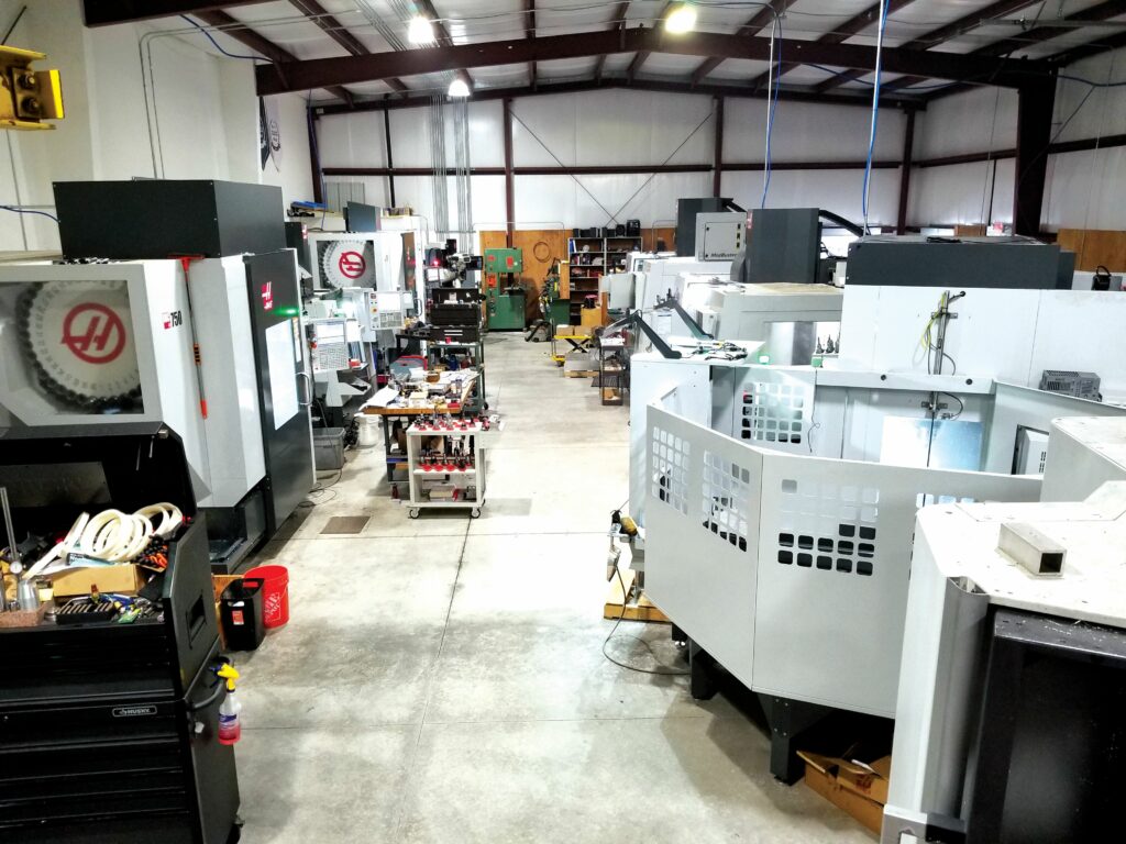
There is an abundance of CNC machining technologies and services available for fulfilling uncrewed vehicles’ structural and powertrain needs. Rory Jackson explores some of the key aspects thereof
Across military and civilian industries, the world of uncrewed systems is growing fast, with tenders and orders for intelligent vehicles being announced more rapidly than ever. OEMs, both small and large, together with their subsystem suppliers, are expanding their production capacities to meet the heightening plethora of tasks and responsibilities entrusted to mobile autonomous aerial, terrestrial and marine assets.
Though much of the uncrewed space is marked by use of composite material hulls and structures, we have recently seen a growing number of manufacturers achieving immense success through reliance on the types of metallic structures used consistently throughout passenger aviation for many decades now. This is especially pronounced among the larger sorts of vehicles aimed at serious industrial operators, such as ACUA Ocean’s 25.7 t H-USVs (Issue 60, Feb/Mar 2025) and ACC Innovation’s 800 kg Thunder Wasp UAVs (Issue 59, Dec 2024/Jan 2025).
With more of such vehicles being produced – highly bespoke and optimised for critical niches – the need is growing for orders of non-standard structural parts that cannot be purchased from stock metal suppliers. Hence, CNC machine shops are increasingly being frequented, both for the parts their metal milling machinery can provide, and for the specific capabilities of their machine operators and consultants who understand how best to achieve what the customer is looking for.
A CNC machine tool maker or operator, experienced in the needs of vehicle engineers and manufacturers, will ask a great many practical questions (be they direct or hypothetical) when approached by an uncrewed systems customer (or engine manufacturer) to make a part. Those questions will include how to hold the billet before starting to mill it into the part’s shape, where to cut first, where to cut second, where the tightest tolerances will be and how many times the part might need to be repositioned.
Principally, it is the machinist’s job to consider what problem the part design is meant to solve. Aerostructures, for instance, are quite often designed to beat the challenge of strength-to-weight maximisation. Thermal dissipation is another perennial problem among vehicle subsystem housings as well as some fairings and engine parts.
Whatever the exact issue or target, the most competitive machine tool operators today will not unquestioningly follow a customer’s requests and CAD diagrams, but holistically advise customers on the dynamics and particulars of CNC machining, in ways that can save the uncrewed vehicle manufacturer staggering costs, weight, power consumption, lead times and more.
Tight tolerances, for example, can drive up costs, and machinists know better than UAV engineers how to correctly analyse whether all tight tolerances across, say, a bulkhead, enclosure or cylinder head are necessary. On top of that, CNC machines have constraints of their own – such as the X, Y, Z volume of their internal chambers, the materials they can work with or the geometric complexity they can manage – and any customer that asks for a part at the limit of (or slightly over) those constraints will find their per-unit costs shooting up exponentially.
(Image courtesy of Syncro Design)
Knowing some of the particulars of those machine tools, and of the considerations their operators may run through, will be key to the success of the uncrewed world in the years and decades ahead.
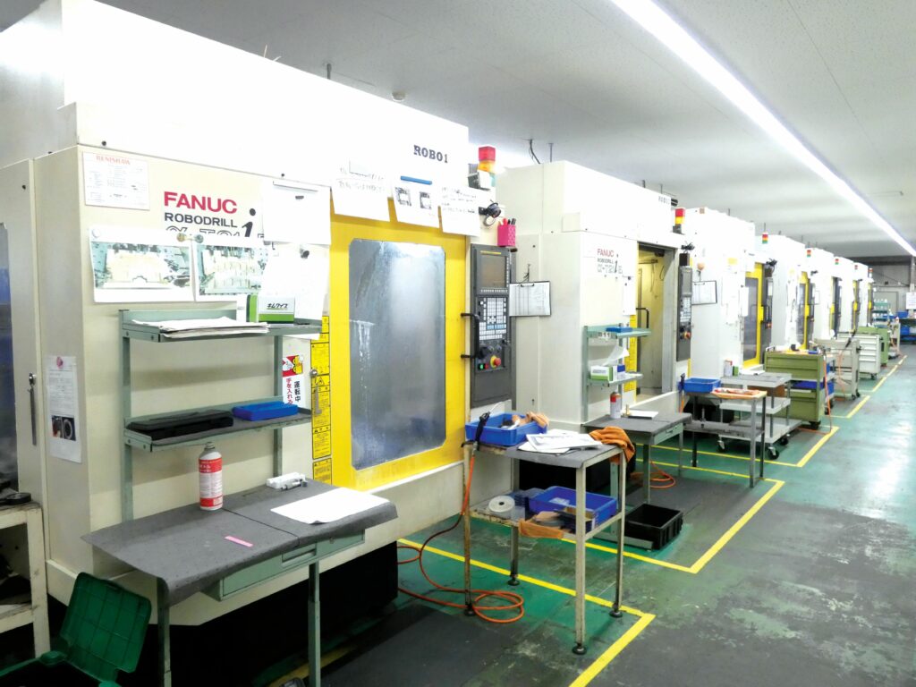
3-axis milling
3-axis milling machines are arguably the most basic form of CNC machines routinely used in vehicle industries. For the unfamiliar, one may effectively picture a sculptor, chiselling away at a cubic marble block, starting with broad strokes before moving to light grinding and sanding, to achieve the curvature of the intended sculpture.
3-axis CNC milling machines works on the same principle: one starts with a block of material larger than the desired part, and a tool is rapidly spun for cutting material away (potentially spraying a cutting fluid such as water, oil or a combination of both to cool and lubricate the tool against the material), until the desired shape – both positive and negative features – is achieved.
As a sidenote, CNC turning machines operate similarly, but by rotating the billet against a stationary implement; for brevity’s sake, we refer here to just milling, rather than turning (or both).
All the while, the block (or workpiece, as one might call it after milling has commenced) is clamped in place as rigidly as possible. Obviously, maximising that rigidity represents a non-trivial barrier to precise machining because otherwise the block will move and slip as the cutting tool makes contact.

In a 3-axis machine, the cutting tool can only move orthogonally, meaning that its movements are limited to the X-, Y- and Z-axes with its path being guided by a computer control system. While AI-generated tool paths are gradually being experimented with, the foreseeable future of CNC programming will still likely be dominated by human engineers, specifically those who can closely understand the order of operations: where to cut material away first (and then subsequent cutting step-by-step) to achieve the desired shape and surface finish, and how to minimise the chances of tool errors and breakages.
The importance of a mind capable of seeing the initial billet around the final component, thinking subtractively about how to get from the former to the latter, and correctly conceiving the order of operations in CNC programming, cannot be understated. The machine itself is essentially a mindless, blind device that will generally carry out the orders plugged into it in a very open-loop fashion.
Thus, when cutting something like a cooling plate, one might for instance create a CNC program that starts with installing a face mill and using it to flatten and smooth the top surface of the block, then replacing it with a spot drill to bore some holes, before swapping in a tap drill to widen or reshape those holes.
However, a cognisant mind remains vital even for such basic programs, particularly because the speed and order with which one removes material will affect the part’s dimensions relative to the target geometries and tolerances. Metals and plastics are formed by heat, and the friction of cutting inevitably introduces heat into workpieces. If thermal gradients and resultant material behaviours are not accounted for, one may find that, upon being de-clamped from the milling chamber, the workpiece deforms into an entirely unacceptable shape as it cools.
Additionally, as the cutting tool spins against the workpiece, possible tool deflections are a perennial concern and cause of imprecise geometries and depths. Tool deflections can be caused by an excessively high cutting speed (a natural reaction to wanting a part finished faster) or by a variety of other factors such as insufficient tool strength for the job or excess overhand of the tool from its holder. Such factors might also cause inaccurate cutting and grinding owing to the tool bouncing unpredictably off the material. Again, machining experience is critical to predicting and avoiding such behaviours for consistent quality parts.
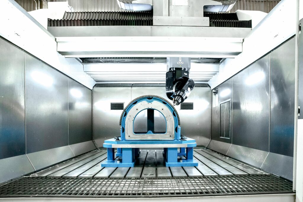
5-axis milling
When looking for parts of higher design complexity than a 3-axis machine can cost-effectively provide, one can find CNC machines with up to 12 axes (anything beyond being very uncommon), and 3- and 5-axis machines are arguably the most widely employed – at least among the CNC machining services providers that we have seen – and thus the most useful with which to gain familiarity.
Broadly, 5-axis machines can be separated into two categories. One may be thought of as ‘3+2’ axis machines and the other as full, simultaneous 5-axes-at-once machines.
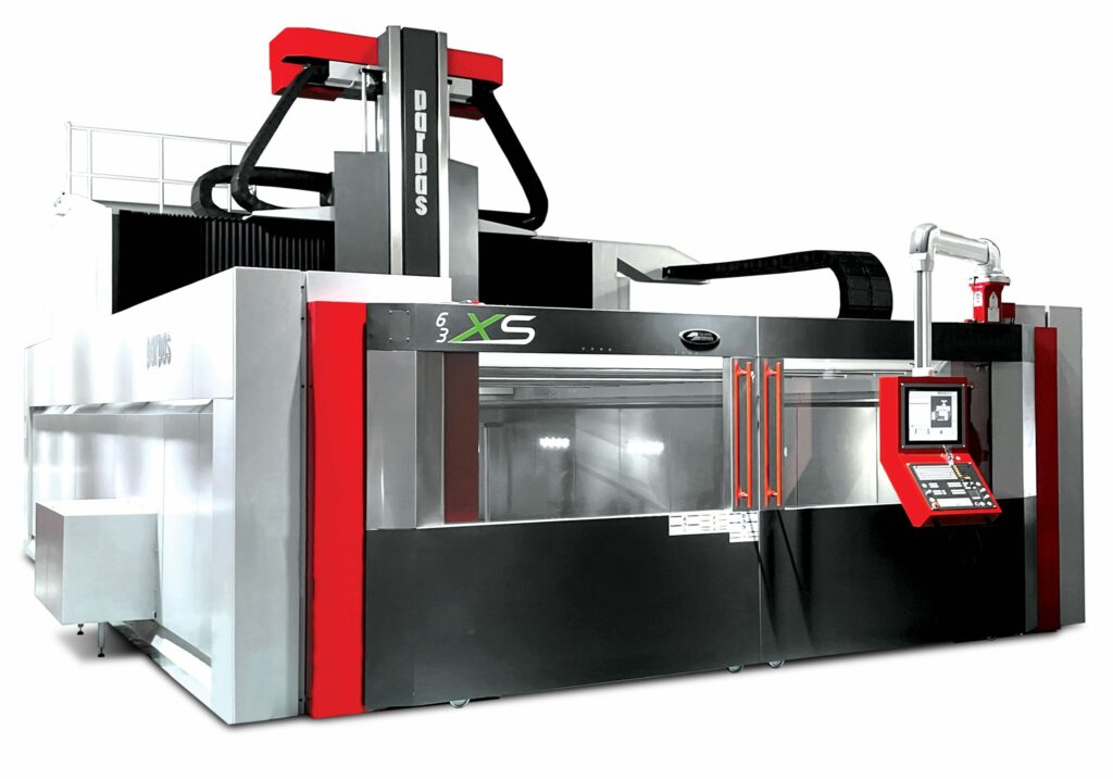
(Image courtesy of Gruppo Parpas)
The former is effectively a 3-axis machine for cutting in the X-, Y- and Z-axes, but upgraded with additional A- and C-rotary axes via which the workpiece can be moved between milling stints. Thus, each block can be worked by the cutting tool in the three orthogonal axes from multiple different angles (but the workpiece cannot be rotated in both the A- and C-axes at once), without having to stop milling, open the machine chamber and reposition it manually.
While this might sound like a minor change, it dramatically eases workflows for CNC machined parts and, by extension, enables far more geometrically detailed and complex parts in a given set-up by virtue of that complexity no longer driving up labour hours per unit produced. For example, 90% of a complex component such as a turbocharger housing or cylinder head can be finished in a single stint and then moved to a simpler 3-axis machine for the final phase.
A minor caveat is that pre-programming time increases with the number of axes used per machine, meaning that the 3-axis machine will get started quicker than the other, more costly, machines. However, those other machines will quickly speed past in terms of cutting progress, units finished per day and production costs per unit, particularly as order sizes increase.
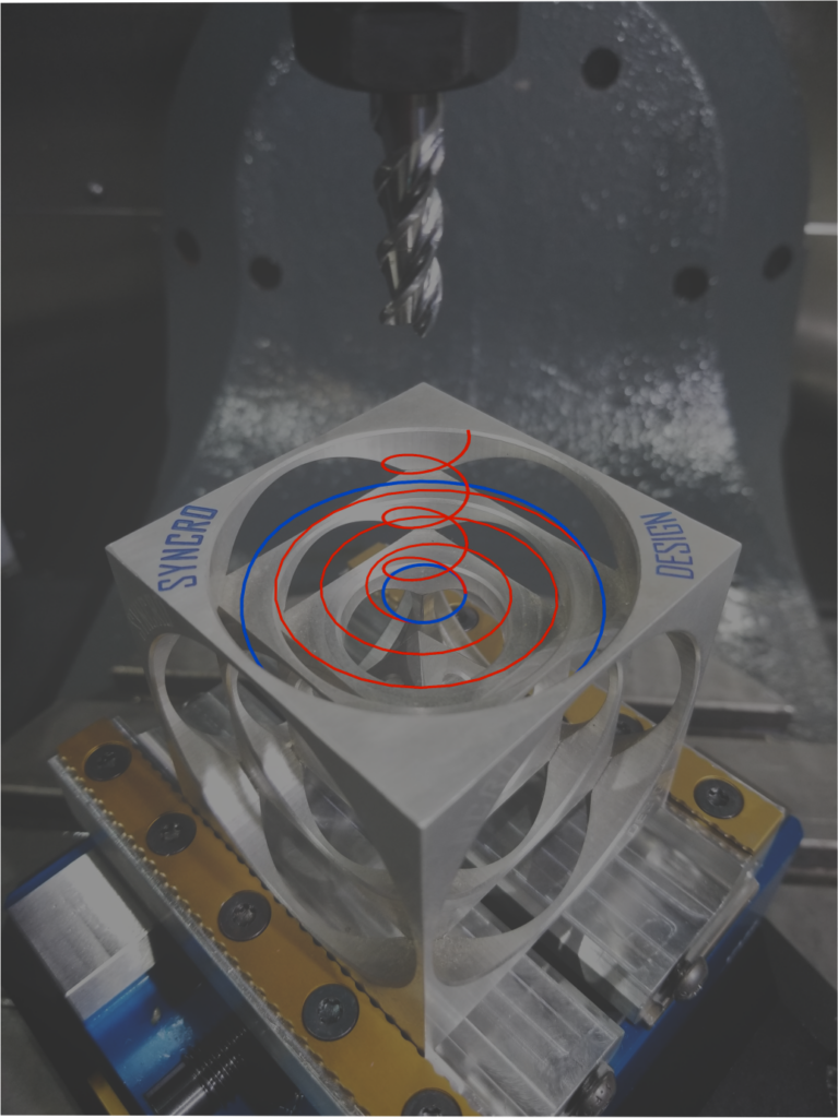
In the latter category, the relative angle between the workpiece and the tool can be changed in both the A- and C-axes simultaneously, meaning that the workpiece can be re-angled dynamically as the cutter spins. That enables the geometries necessary to account for fluid flow in complex, helical, CFD-optimised parts such as propellers, impeller wheels or gas turbine diffusers.
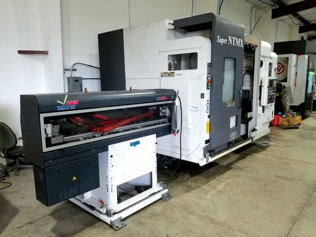
Multi-spindle machines
Given the extremely fine and performance-critical tolerances one must adhere to in producing impeller wheels, be they for gas turbine engines, turbochargers, superchargers, pumps or other uses, casting and forging such parts efficiently is challenging. High-quality CNC machining services are therefore crucial for either cutting impellers from an initial block of metal or grinding a cast part to the final dimensions. Furthermore, owing to the complexity of impellers, they are often regarded as the most difficult components to mill, and the ability to do so competently is regarded as a mark of quality.
In addition to standard 5- or more-axis CNC machines, multi-spindle machines are highly useful in producing parts of such detail and curvatures. Mill-turn machines, for instance, can integrate two opposite lathes facing each other, with an axis in between integrating live tooling, for milling, turning or drilling a workpiece clamped into one of the two lathes.
As the tooling cuts the workpiece, that lathe can rotate it about a given axis, enabling the higher than standard milling detail typical of a 4-axis CNC machine. Moreover, the lathe can then ‘hand off’ the workpiece to the other lathe at a certain point, thereby enabling the tool to access the workpiece’s back side, and therefore cut all sides of a part to spec in one set-up.
In a high-end multi-spindle machine, the central axis may constitute a multi-axis milling head, such as a five-axis turnable tooling system, be it all five axes simultaneously or a 3+2 system where the cutter rotates in a single axis at a time. Either way, perfectly square parts (if so desired) or intricate, delicate parts designed with symmetry in many axes can be machined in such solutions without any stops to manually reposition or re-clamp the workpiece.
(Image courtesy of Kagoshima Seiki Co., Ltd.)
Impellers, particularly, could be milled to spec with exact gradients of all inducer and splitter blades, without any interaction from technicians or machine operators following the first cut into the raw metal bar stock – especially if the multi-spindle machine comes with a parts catcher, for taking hold of the finished part from the lathes and mechanically placing it outside of the work chamber in an automated fashion.
Challenging materials
As one might expect, the more mechanically robust a metal, the more of a challenge it is to machine-cut it precisely or cost-effectively.
Stainless steel is arguably the prime example of this, being well-known as a material with high strength and high corrosion resistance; properties that naturally make some stainless steel grades very difficult to cut. Moreover, being a ductile material, its strength increases during permanent deformation, a process known as work hardening or strain hardening. This process can occur when cutting stainless steels and other high-end metals similarly sensitive to work hardening.
For example, titanium is also prone to work hardening. Additionally, owing to its very low thermal conductivity, it can easily induce localised heat buildups during the machining process. Both properties will have an impact on the tool as titanium is milled to the customer’s desired specifications; in general, titanium will get cut much more easily than steel, as long as the machinist is using an extremely sharp tool and holding the workpiece firmly.
Fortunately, significant advancements in tools for cutting titanium have been made in recent years. However, in any event, the tool will dull at an accelerated pace compared with that of a tool used to cut easier, cheaper block materials less susceptible to heat buildups or work hardening, and there is little to no means of remotely sensing that degradation. Ultimately, knowing when to replace a tool before a breakage (and possibly an irrevocable mistake in the workpiece) occurs comes down to the machinist paying close attention and using instinct derived from either experience or good training.
Inconel alloys are known to have similar mechanical strength, thermal resistance and applications as titanium alloys, and it follows that they are similarly problematic for CNC machines. Hence, good CNC workshops capable of working with such material are a rare find because it takes weighty experience, specialised tools and expensive machinery to do so properly.

Beyond metals, many CNC workshops work with a variety of plastics, such as Teflon, which are widely cut to shape for underwater seals. However, while Teflon is easily bent and pressed into shape, it does not yield to cutting easily: instead, it will tend to deform away from the implement while being cut, returning somewhat to its original shape once the tool withdraws from the plastic. Hence, Teflon and some other plastics can be extremely challenging (and thus potentially costly or time-consuming) to machine-cut with tight tolerances.
On top of that, some plastics are prone to absorbing water during the cutting process (particularly when water-aided tooling is used). Hence, some workshops will perform a dry cut or otherwise keep an industrial oven for drying finished plastic parts to extract moisture from them. Such parts may also be shipped in a vacuum-sealed bag filled with a desiccant material to prevent moisture absorbance during transport.
Moreover, glass- and carbon-reinforced plastics – otherwise known as composites – might also be subject to CNC machining, such as the boring of holes for fasteners or cables. As most of our readers will know, carbon composites are among the highest strength-to-weight materials in our shared industry, and fibreglass composite is also highly abrasive when cut, requiring high-quality tools (and frequent checking and replacement) for both.
Among the least challenging and most cost-effective materials used in CNC machining today are aluminium alloys, with 6061-T6 being the metal used most widely for machine cutting. Despite its high strength-to-weight ratio, it cuts far more easily than steel and titanium, and it is better at absorbing heat and avoiding thermal deformations than many other metals. Additionally, given the commodity nature of aluminium, it can be acquired from a huge variety of suppliers in tubes, cubes, sheets, bars and other shapes in order to produce anything from a landing strut, to a body fairing, to an engine block.
(Image courtesy of Kagoshima Seiki Co., Ltd.)
Many aerospace customers are also increasingly seeking machined 7075 aluminium parts because of the material’s greater strength-to-weight ratio. Although it is harder than 6061 and hence goes through tools faster (as well as being costlier), it cuts more easily than stainless steel and titanium.
The survey UAV market in particular might benefit from the rising number of CNC companies capable of working with materials such as Invar. These nickel-based alloys exhibit an extremely low thermal expansion coefficient – similar to that of glass – as well as very low magnetism, making them ideal for lens-holders in optical systems. However, as with titanium, cutting this material precisely and efficiently takes a certain learning curve, potentially including a plethora of test cuts before a workshop can supply Invar parts with volume, consistency and confidence.
Quality control
As mentioned, the tool and the machine are typically blind systems that cannot provide reliable feedback to the machinist as to whether the workpiece and the tool are faring well. While one might assume that a laser or similar type of scanner could be integrated within the milling chamber for mid-process measurements of the part, attempts at such configurations have been hampered by constant occlusions from the tool and from the powders, moisture and debris prevalent throughout the chambers.
There are a few exceptions and workarounds to this, however. One of the simplest is that some CNC machines will integrate physical probes – be it a workpiece probe, a tool probe, or one of each – consisting, for instance, of a sapphire on the end of a plastic needle (not dissimilar to CMMs) that the operator can manually call upon to accurately measure different features of the workpiece or the tool while the cutting machine is stopped.
Alternately, such probes can form part of a CNC programming set-up, designed to take measurements of tools or workpieces while in-process. Theoretically, a high-priority geometric feature on a customer’s part could be manufactured by ‘walking it in’; for instance, a hole could be bored inch by inch, with the tool extending into the block some way, then retracting to allow a probe to take internal measurements.
With that precise data gathered, the CNC programmer could account for any insufficiencies thus far in the hole’s width or inconsistencies in its geometry while programming the machine’s next (and possibly corrective) steps. This approach can also be adopted for the tool when cutting stainless steel or an especially stubborn titanium, measuring it at regular intervals to identify early signs of wear.
In general, greater automation is becoming key, not only for ensuring consistent quality but also for resolving the immense workforce cost that comes with operating and maintaining CNC machinery. Achieving automation in CNC machining is challenging, however, requiring close pairing with production planning software, automated tool checking and replacement mechanisms, supervising algorithms, robotic arm-type systems for installing blocks and removing workpieces, autonomous carting of raw materials and finished batches, and more – all of which together demand great expense and time.
But once all this is done, being able to press a button and know with confidence that a series of parts will be milled and finished as required, even through the night or over multiple shifts and days, without the need for an engineer to continually check that no mistakes have been made, will become invaluable as long-endurance UAVs and other uncrewed systems become ubiquitous across various industries.
(Image courtesy of Gruppo Parpas)
One machine producer has, to that end, patented an approach for helping maintain close temperature controls about the CNC machine tool, to minimise the degree of thermally induced deformations and errors by the tool upon the workpiece. That method consists of placing covers about the gantry for the machine tool chamber, and blowing temperature-controlled air between those covers to cool the back part of the machine and keep it sealed against external temperatures, both outside and inside the machine chamber.
(Image courtesy of Syncro Design)
New methods for maintaining the accuracy of weighing scales used inside machines (highly valued for checking that the correct amount of metal has been carved, bored or ground away over time when present in a machine design) stand to make a similar difference as thermal management innovations in the CNC space.
Sheet to sheet

So far, we have considered machine tools for CNC milling, turning and drilling. Over the past several decades, however, machines for precisely and consistently working metal sheets – in a programmed and thus more automated fashion than manual machine brakes for metal bending – have been optimised and diversified with CNC punch presses and press brakes being notable examples.
A CNC punch press typically comes with a rotating head, full of tools of different shapes and sizes, each of which can be taken in order to profile metal sheets as programmed. As well as punching holes or cutting lines through the metal (the latter including cutting away corners to achieve non-rectangular perimeters), the punch press can emboss, deboss or create tapped holes for screws.
Once all the two-dimensional qualities of the sheet are achieved, it can be retrieved and placed into a press brake, which can be programmed with an order of bending or folding operations similar to the various cuts of a milling or turning machine.
The press brake will typically consist of a fixed bed, with a V-shaped tool for imparting bending force, and a beam for receiving that force and pressing the sheet against the tool. Press brakes generally differ in terms of the bed sitting at the bottom and the beam at the top, or vice versa.
Either way, they will perform a series of folds to turn the sheet into a tube, a rectangular beam, a half-cylinder or whatever other shape is demanded. Much like a 5-axis milling machine, the steps can usually be executed one after another in an uninterrupted chain, without any express need for the machine operator to perform manual checks or readjustments of the workpiece.
The future is software
While improvements in the core performance capabilities of machine tools are expected to level off over the next decade, it has been expressed to us that significant software improvements have been happening over the past 5-10 years, which pose the likeliest avenue for further advancements in the CNC space in the years ahead.
The complexity and value of control software products often run in hand with those of the machines they are best suited to be used with, with simple software solutions like Fusion 360 by AutoDesk or Haas’ control systems living at the lighter, simpler end of the spectrum, and more complicated software like ESPRIT being necessary for machines with more axes, options and dimensions.

Theoretically, both types of software products can produce exactly the same kinds of parts; however, the processes adopted to achieve the same dimensions and finishes would be wildly different. The former type is streamlined compared with other multi-axis CNC software packages, and thus much easier to train new technicians to use, including those with little to no experience or education of CNC machining.
The latter type comes with a much steeper learning curve, lacking much of the guidance and helpful graphics of the former, while offering significantly tighter and faster controls, and wider capabilities for timing and combining different subsystems inside CNC machines – so much so, that something like a multi-spindle machine would require ESPRIT or something similarly intimidating.
Some in the CNC space have been known to scoff at the very streamlined and simplified approach taken by the likes of Haas toward both their machines and their accompanying control software (including several series of training videos on YouTube). However, it is anticipated that providing greater automation, streamlining and training resources for CNC machines is likely to be undertaken more and more by machine suppliers worldwide (including those associated with the highest complexity and quality of machinery) as companies try to lower the costs associated with training and replacing machinist staff, as the average age of machine tool operators rises and staff shortages start to mount.
Another key step toward that streamlined future is expected to be increased integration between machine tools and 3D CAD data, including the ability to embed product manufacturing information into CAD diagrams to enable CAD designers and engineers to pre-inform how CNC and computer-aided manufacturing technicians program their milling set-ups, saving time and ensuring parts get sculpted and finished to exact preferences.
The use of generative AI also represents potential gains in terms of helping create milling programs, and intelligent analytics for predictive maintenance of machine tools stand to save hugely on CNC production costs by avoiding major breakdowns before they can happen – much as is the case for uncrewed vehicles themselves.
Acknowledgements
The author would like to thank Brian Davis at Syncro Design, Gianluca Battisti at Gruppo Parpas, and Hayato Kariatsumari of Kagoshima Seiki Co., Ltd. for their help in researching this article.
UPCOMING EVENTS


