


Rotron RT600-HC
Spin master
Rory Jackson looks at the development of this Wankel engine designed for rotorcraft vehicles
We last featured Rotron Power in UST 4 (Autumn 2015), its RT600 twin-rotor Wankel gasoline engine having enjoyed significant commercial success, in both of the versions that were then available. One of those was the RT600-LCR (for ‘liquid-cooled rotor’) which thermally managed its rotor via charge cooling, the other was the RT600-XE (for ‘exhaust ejector’) which used a vacuum ejector system to pull air through the engine for cooling the rotor. Both also used liquid cooling for thermal management of their housing and eccentric shaft.
Since then, the company has continued to evolve its engine designs, and reshaped its engine production line and commercial approach in response to the changing landscape of the UAV industry.
For example, it has discontinued the LCR and replaced it with the RT600-HC (for ‘helicopter’) rotorcraft unit. The RT600-XE is still available, principally for non-helicopter UAVs and small aircraft, although it has a lot in common architecturally with the HC.
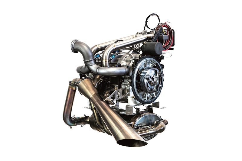
Both are twin-rotor gasoline and heavy fuel Wankel engines with a 600 cc displacement, and with geometric similarities to the famed rotary design that was based by motorcycle manufacturer Norton on the Fichtel & Sachs KM914. Key differences between the HC and XE are power, weight and general performance.
The XE is a 44.5 kg engine (including all ancillaries) with a 100 bhp peak output and 70 continuous bhp, while the HC weighs 39 kg (again including all ancillaries), with a peak power of 64 bhp and maximum continuous output of
46.5 bhp. These figures are more suitable for the power requirements of helicopters during their various flight modes, as well as the stricter weight limits imposed by the absence of fixed-wing lift.
Looking at the power and torque curves of both engines as mapped across their speeds shows that when the HC is delivering its maximum continuous power, at about 4000 rpm, it generates 58 lb-ft (79 Nm) of torque, only slightly less than its peak of 59 lb-ft. This is a desirable property in starting and driving a helicopter’s top rotor, and the HC has a broadly higher torque-to-power ratio than the XE.

The HC is Rotron’s leading commercial success story at the moment, hence our focus on it here. However, the company has become agnostic regarding the type of engine it is asked to supply, and now often operates as something of a Tier 2 provider rather than aiming to work as a bulk manufacturer of COTS engines.
“We’ve found that the UAV market is either tiny start-ups who want just one of our engines, or aerospace primes like Leonardo who have a detailed set of requirements and need continual support for the engine technology during integration and use,” says Alex Head, managing director at Rotron Power. “For the latter, the core rotary engine technology is really only as good as the ancillary systems and the ongoing support.”
As a result, Head notes, while Rotron does supply COTS engines, the reality is that every unit needs to be customised, as dictated by their missions and installations. “Helicopter integrations in particular are a really difficult use case for an engine, because it’s high power and low airspeed, so there isn’t much cooling,” he says.
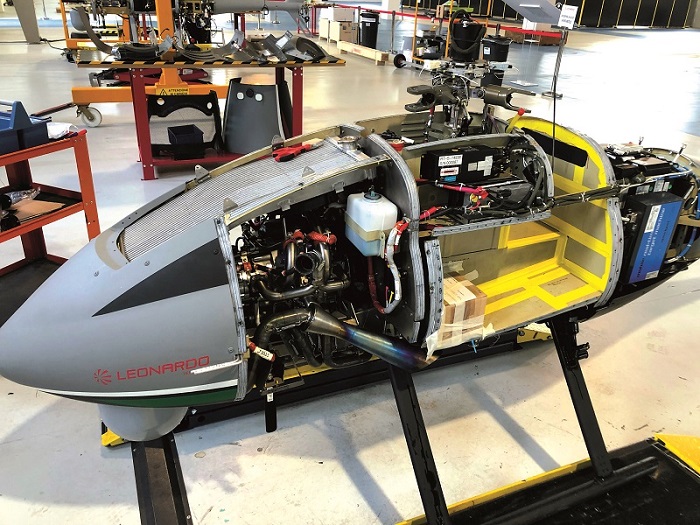
“However, since we last spoke with you, we’ve gone on to integrate our engines into many such platforms. Leonardo’s AWHERO for instance is the world’s first military-certified rotary UAS in the 200 kg class, and it incorporates their version of the RT600-HC. There are other certified Wankels out there, but only for motorised gliders.”
The certification has provided Rotron with new levels of insight into fault hazard assessment, reliability, safety and other qualities that are key to maturing engine systems, as well as a range of improvements across its engine subsystems. At the same time, the company has invested a lot of r&d in achieving a ‘design for manufacture’ approach for its engines.
Manufacturing changes
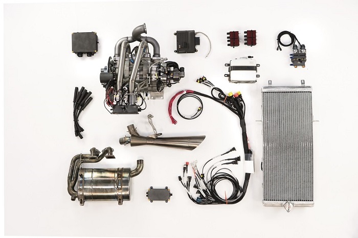
Many small changes have been made across the RT600’s core components (along with a few larger ones to essential ancillaries). The improvements have been driven by the aim of providing the longer TBOs and lower maintenance costs often demanded by modern UAV integrators.
As Head explains, “I look at engines in terms of brake mean effective pressure – that is, cylinder pressure, and how much work the engine’s doing. The RT600 has a large cubic capacity, but when we use it in rotorcraft it’s rated at a lower duty cycle for maximum continuous power, so what we’ve sought to bridge with the RT600-HC was a gap in durability for rotary engines.
“Some might compare our engine with others and find there have been 300 cc Wankels that output 55 bhp on their data sheets, but in reality they can’t do that for thousands of hours. That makes them more expensive to run, and complicates their supply chain logistics.
“Instead, we’ve opted for a 64 bhp peak distributed across two rotors that operate within their thermal capacity. Even at that peak, there’s no flexing of the apex seals, no wearing of springs, none of those issues that can plague rotary designs that sacrifice durability for power.”
That has enabled Rotron to redesign components for lower weight. For instance, the rotor housing is still cast from LM25 aluminium alloy, as it is a free-flowing casting material, and the end plates and centre plate are cast from LM13. After casting, these are heat-treated and subjected to non-destructive testing to confirm the absence of leaks.
“We use precision sand casting, and we’ve worked closely with foundries to remove weight, particularly in the end plates,” Head says. “We use either Hadleigh or Hayworth for the casting, and as well as being very capable they also use some sophisticated flow software to ensure the liquid metal flows as expected.”
After casting, the housing parts come to Rotron to be put through several processes in its machine shop, to make them ready for internal nickel silicon carbide electroplating by Poeton. After that, A&M EDM in Birmingham, England, performs precision grinding of the trochoid followed by wire-eroding, a form of electrical discharge machining (EDM).
Head comments, “A&M don’t use abrasives; EDM is incredibly precise and reliable. It can cut hard metals with an accuracy of around 10 microns so long as you control the temperature well, and it leaves a good finish.”
Some more post-processing in Rotron’s machine shop follows, before the housing parts are then checked on a coordinate measuring machine, before being given serial numbers and entered into the company’s parts stocks.
Rotron can also supply modified versions of the end plates that come with integral mounting points for interfacing with gearboxes, belts and other ancillaries, although there is trade-off of a slight increase in weight for the easier ancillary systems installation.
Shaft and rotor
Some issues with the engine’s eccentric shaft, particularly when the engine was being used to drive large propellers through offset reduction drives, have been found and mitigated. “In short, we had some stress-raisers inside the end of it,” Head explains.
“The shaft used to have a very deep bore on the inside, so we’ve reduced its length and fully radiused it to lessen any stress-raisers inside. It never had any issues when, say, driving a gearbox spindle, but we wanted a single shaft that would fit every application, so when we found this issue it was an obvious improvement to implement. It makes manufacturing a bit more challenging but ultimately it’s been worth it.”

The rotor meanwhile has had some changes made to the orientation of its internal cooling fins for improved thermal management, along with some proprietary changes that Rotron declines to discuss.
“We also brought all the gear cutting in-house, largely to control the tolerances ourselves – specific niche processes like backlash measurement and engine balancing,” Head explains. “We balance the rotors individually, then balance the assembly sub-components and eventually the whole engine, all through processes we’ve developed ourselves.”
Other aspects of the engine have been kept largely unchanged over the past 7 years. For instance, the eccentric shaft still runs in two bearings, with a tapered spherical roller bearing at the output end and a standard roller bearing at the other. Internal r&d has investigated alternative arrangements such as central bearings and split bearings, but ultimately the simplicity of a two-bearing design means this architecture has stood the test of time.
The apex seals are also largely unchanged, except that they are now produced in ingots and then cut to specified tolerances, rather than being investment cast, as they were in the beginning.
“That ensures the processing, measurement and passing requirements of the apex seals can be matured, but more importantly they can be controlled to zero in on their working tolerances relative to the dimensions of the rotor, springs and housing,” Head says.
Modular intake
The throttle and airbox largely differ for each customer, and Rotron uses an interface control document with about 40 different potential interfaces between the engine and aircraft to define the air intake componentry and the key parts around it.
The customer typically provides a shielding that should lead from a NACA duct on the outside of their fuselage, which interfaces with a rubber seal onto the airbox. The seal is designed by Rotron as needed for the end-user’s packaging and volume requirements, and if feasible it integrates an air filter and moisture separator to clean the air before it flows into a set of throttle bodies.
“We’ll also change the aperture sizes of the throttles,” Head says. “High-altitude applications for instance need more air, but if say you’re not at high altitude and need only 58 bhp, then a smaller aperture could yield great benefits in terms of controllability.
“Our ECU also acts as the governor, so we can tailor different percentages of throttle opening ranges to certain percentages of available shaft horsepower.
“We use a Volz servo for throttle control, which gives a lot of feedback for fine control and real-time diagnostics, and it can be pre-programmed in a number of ways to mitigate failure modes that different use cases might induce.”
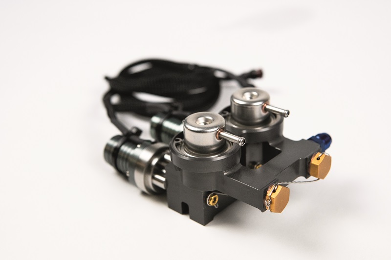
A twin-pump fuel system has been developed in-house for a redundant fuel supply to the injectors. Fuel is sprayed after the throttle discs to prevent icing problems from condensation on moving components, an increasingly pressing issue as organisations seek to fly their UAVs higher and in extreme climates below -20 oC (despite helicopters typically not being safe to operate at such temperatures).
The charge is sent down a set of pipes – some titanium, some aluminium, depending on the installation – directly into the inlet port.
Rotron says it has experimented with direct port injection, high-pressure direct injection and other approaches, but has found that port injection high in the intake stream, just below the throttle, provides very good atomisation and mixing thanks to the length and wave energy of the charge.
Engine management
Rotron borders on calling its current ECU a FADEC (full authority digital engine control) but points out that fallback control by a remote operator is still technically possible, so in some applications the system does not fit the exact definition of a FADEC. However, considerable time and resources have been spent on optimising it for full authority control in all speed regimes, along with other capabilities beyond most COTS ECUs.
The system has been co-developed with General Engine Management Systems to tailor its functions to UAV operations. It is a major departure from Rotron’s use of an aftermarket automotive ECU used in motorsport.
“For instance, the ECU continually tests and checks the twin-pump system to ensure it’s functioning correctly, and if one were to fail it would trigger a check valve to ensure fallover to the next pump,” Head says, adding that it will also send a warning signal to alert the platform’s flight controller.
“For rotorcraft and hybrid applications, it’s important that the engine can manage itself relative to load, and we have full control and access to tune and develop the rates and gains within that, to ensure the engine can maintain a given rpm if needed.”
The ECU’s programming, diagnostics and commands take place over CAN. A lambda sensor is installed for closed-loop control of the air-fuel mixture, although if the sensor fails the ECU drops back to its base mapping for open-loop control.
“We also use manifold air pressure [MAP] sensing for engine management,” Head adds. “We used to do a lot solely on throttle position sensing, but found MAP gave better repeatability and throttle response.
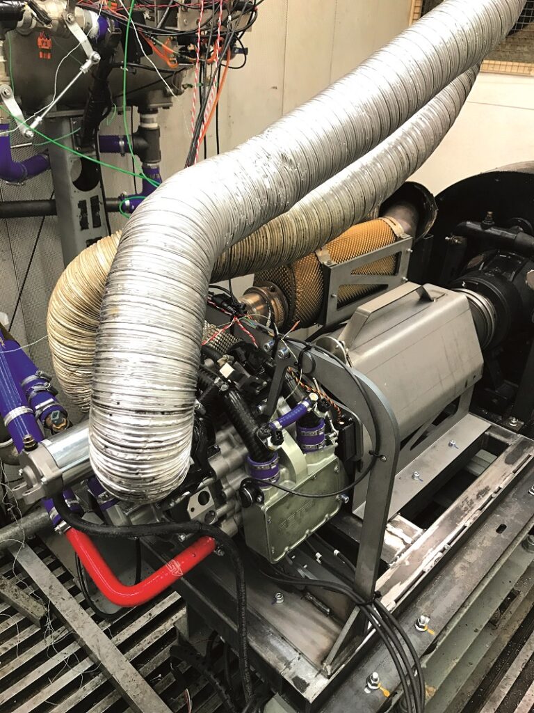
“We’ll add a lot of standard engine health sensors for things like fuel pressure, and the higher the altitude, the more we’ll want to measure things like vapour lock, temperatures and resonances in fuel systems. Fortunately, we have an altitude testing chamber that has been critical in developing the ECU and ancillaries, and for running the engine on Avgas, which is important for higher altitude use cases.”
Ignition
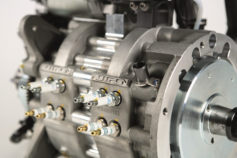
The version of the RT600 featured in UST 4 was notable for using four spark plugs – a pair of twin plugs per rotor. Through research into multi-fuel and heavy fuel Wankels around that time, Rotron had also begun experimenting with designs with four spark plugs per rotor, and Head notes that some test prototypes used far higher numbers.
“Those helped us experiment with how greater numbers and different arrangements of spark plugs could aid the efficiency of the burn, and we eventually settled on a compromise of four plugs per rotor in the standard RT600-HC,” Head explains.
A 2 x 2 arrangement of plugs visible from outside the engine achieves the desired spread of ignition across the combustion chamber; these fire as pairs in a phased order. Rotron says this firing order has increased fuel efficiency significantly, equating to an additional 3-4 bhp across much of the operating range, as well as achieving a cleaner burn.
Inside, the trailing spark plugs in each group sit inside what Rotron calls a ‘pre-combustion chamber’. This is not a chute- or pepper pot-type pre-chamber as might be seen in reciprocating diesel engines, but a hole drilled into the epitrochoid to carefully specified tolerances, which contains the spark plugs and is pressurised with the introduction of charge.
“The charge is ignited in the pre-combustion chamber as well as in the combustion pocket, providing an extra bit of burn as the flame front moves across the combustion chamber,” Head says. “Because of the way we’ve shaped the pre-combustion chambers and the phased firing order around the flame front, we get a much cleaner, fuller burn than in previous versions of the engine.”
The trailing spark plugs are standard electrode-type plugs, while two slightly more expensive surface-discharge spark plugs are used in the leading plugs, this type having originally been invented for use in Wankels to prevent impacts with the apex seals.
“Rotary engines have a long, thin, moving and square-shaped combustion chamber, which naturally makes it hard to achieve the efficient squish of a reciprocating engine’s round combustion chamber, and the way the charge is compressed into the spark plug in the middle,” Head explains.
“But we’ve changed the profiles of our rotor’s combustion pockets over the years to have a more leading shallow shape, with greater compression towards the rear flank of the rotor to achieve the best squish characteristics.”
Exhaust ejector
The improvements in the design of the combustion chamber have made for a more effective squish and a more efficient burn in the RT600, while also producing greater concentrations of heat on the leading edges of the rotor.
To counter that, a leading-fin design has been adopted that more effectively conducts heat away from the combustion pocket that sits in each of the rotor’s three sides. This in turn makes for a faster and more efficient heat exchange between the rotor’s internal fins and the cooling air that passes through the rotor.
In 2015, the RT600’s rotor was either charge-cooled as per the LCR version, or cooled using an exhaust ejector system as per the XE (although in our previous article, Rotron referred to it as an ‘exhaust extractor). These days, both the HC and XE versions use a system that is an evolution of the original exhaust ejector, in this case having been optimised for aerospace rather than racing.
“We can still do charge cooling, but that inherently has a power limitation, because it heats the charge and reduces its density before it can enter the combustion chamber,” Head comments. “That could have benefits for heavy fuel or multi-fuel operations, but if you really want to ensure cool, clean air in your gasoline combustion chamber, we have an exhaust ejector.”
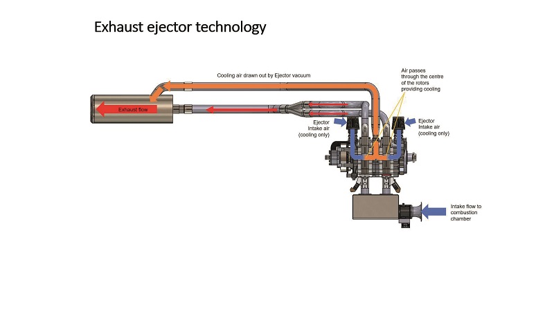
The system works by using exhaust gas velocity to generate a vacuum, which in turn draws cooling air through the engine via the Venturi effect – as used by Teledyne Energy Systems (UST 35, December 2020/January 2021). Teledyne’s fuel cell uses a Venturi ejector to passively manage its reactant gases, without the need for pumps, actuators or other moving parts that could fail while a vehicle was out in space or underwater.
In the Rotron ejector, exhaust gases exiting the combustion chamber flow into a manifold, connected to which is a channel running from an oblong aperture on top of the centre plate, which serves as an outlet for cooling air.

The wide shape of the manifold relative to the prior exhaust outlet causes a drop in local static pressure, and the ensuing pressure differential between the manifold and the air channel induces a vacuum in the latter.
Inlets for cooling air sit on the side plates, and the vacuum draws air into them through the stationary gear on the side plates, picking up oil and helping to lubricate the shaft and rotor bearings in the process before being sucked out of the centre plate aperture, into the ejector manifold and finally expelled from the engine.
Inside the sealed elements of the rotor housing is a lemon-shaped aperture. In addition to holding the stationary gear and eccentric shaft, this aperture is where the cooling air passes and is briefly concentrated to conduct heat away from the rotor.
As the aperture is completely sealed, the cooling air is prevented from entering and contaminating the combustion chamber. Given the oiling assistance it provides to the bearings, what enters the ejector typically ends up being a mist of air and two-stroke oil.
“Since 2015, we’ve matured our exhaust ejector into a piece of technology that we can integrate into lots of different aircraft and engine configurations,” Head says. “Of course, it has to be tuned for fluid dynamics and specialist materials depending on the use case, but as with any Venturi pump system it has no moving parts, which keeps it 100% reliable.
“And since the energy of the exhaust gases would just shoot out of the engine unused without this system, essentially we’re recuperating otherwise wasted energy without any detriment to engine power.”
The absence of pumps, belts and gears also keeps the system lightweight; even the ejector manifold weighs no more than a typical set of mufflers and exhaust pipes. The expansion of exhaust gas in the manifold does create some noise, but Rotron says its customers are satisfied with the present configuration and its performance.
The ejector is typically fabricated and pressed in-house, using a combination of Inconel and titanium to endure the high exhaust gas temperatures. The exact material choices are determined by the specifics of the installation, particularly regarding weight and noise requirements. Titanium is more appropriate for ‘cooler’ parts of the ejector, while Inconel goes into the ‘hotter’ sections.
Liquid-cooled housing and shaft
The housing and eccentric shaft are still cooled by a water-glycol mix, as per the LCR and XE, but rather than still using an impeller to draw water through the shaft and then send it into the housing, the HC uses a pump with a bypass valve installed to apportion the water flow between the shaft and the housing.
“The main failure mode of rotary engines is that, as they run at higher power, they heat up and near the tempering points of their metals, reducing their hardnesses, weakening bearings and so on. So getting fine control over the coolant flow, through repeated CFD analysis, has been a big focus of our activities in recent years,” Head says.
“CFD showed us that our old approach of drawing coolant in from the back and then out at the back again caused some thermal issues, so now it flows diagonally across the engine. It goes in one side of the housing, around that housing, and through the centre plate before mirroring that journey through the other rotor housing and then out of the engine.
“We’ve also designed a number of bleed apertures across the coolant flow of the engine, as well as larger waterway unions. Those, along with the bypass valve, help us control the thermal management via the ECU while generally increasing our cooling capacity.”
Aluminium piping connects via rubber ends between the engine’s coolant ports and the end-user’s arrangements of tanks, pumps and radiators, to optimise reliability for installed mass.
Ancillaries for the liquid cooling are a major focus of the customisation for each end-user, as parts such as radiators must be shaped differently to fit the fuselage of each aircraft, along with tailored parameters such as thinner cores over a larger area for greater heat rejection.
“Fans for cooling the radiator also need to be positioned and sized appropriately on a case-by-case basis, as helicopters spend a lot of time in stationary air, and you can’t hang a radiator below their propeller downwash,” Head adds.
“Fortunately though, we can now control the fans via the ECU as an automated function of engine bay temperature readings. That’s critical, because in some use cases upwards of 600 W is needed for sufficient heat dissipation, and is part of the reason more and more powerful generators are needed in helicopter UAVs.”
Hybridisation
As with the airbox, different alternators and electric powertrain configurations have been developed and supplied for different customers.
“As standard, the HC comes with a 28 V AC, 1.4 kW alternator, but we’ve configured the electric part of the powertrain in a few different ways over the years, starting with an InnovateUK project a few years back, where we worked with Cranfield University [in England] to produce a series-hybrid powertrain,” Head recounts.
“That used an Emrax motor/generator but we’ve used other suppliers, and we’ve even put generators together ourselves. What we’d particularly like to do is couple the engine to, say, a YASA axial flux motor in order to create a hybridised generator pack that fits all our customers’ aircraft. We’re aiming to do that by raising r&d funding through InnovateUK.”
For now, when it comes to customer requests for electric power within specified voltage, volume and weight constraints, Rotron opts to integrate COTS systems that suit the desired specifications.
Sullivan-Acutronic is among its preferred suppliers for permanent magnet generators and regulator units, and 3 kW systems are typically the largest Rotron has integrated, 1-3 kW versions having become quite commonly supplied to its customers.
“In general we’ll tend towards picking a high-power system but rating it a bit lower than what’s on its data sheet,” Head notes. “Because it’s typically working in the loud, hot and very harsh environment of a helicopter engine bay, even the most mature generators we use are being pushed to the limits of what they can tolerate environmentally.”
Green future
Rotron anticipates an increasing share of its r&d going towards hybridisation for cleaner and more efficient power, with higher energy densities than present battery technology, and the use of alternative fuels such as hydrogen.
“Aviation needs high power density, and burning hydrogen in our engines might be the most reliable and cost-efficient way to achieve that with zero emissions,” Head says.
“Mazda for instance are bringing out their rotary range extender which can run on hydrogen or gasoline, so there’s clearly technical as well as commercial viability in developing our engines in that direction.”
At the time of writing, Rotron had completed some preliminary tests of running its rotary power plants on hydrogen, and is keeping an eye out for the right type of grant funding or partner to take it towards its aim of a hydrogen-powered Wankel engine.
Specifications
- RT600-HC
- Wankel type
- Twin-rotor
- Unleaded 95 octane gasoline or Avgas 100LL
- Naturally aspirated
- Effective displacement: 600 cc
- Maximum power output: 64 bhp
- Maximum continuous power: 45 bhp
- Maximum speed: 6800 rpm
- Specific fuel consumption: 0.26 kg/bhp per hour
- TBO: 250-1000 hours (depending on flight profile)
- Weight: 38.5 kg
Some key suppliers
- Servos: Volz
- ECU: General Engine Management Systems
- Sensors: Bosch
- Electroplating: Poeton
- Precision grinding/EDM: A&M EDM
- Precision sand casting: Hadleigh
- Precision sand casting: Hayworth
- Bearings: Eriks
- Seals: Eriks
- Generators: Sullivan-Acutronic
- Radiators: Docking Engineering
- Radiator fans: Spal
- Coolant lines: SFS Performance
UPCOMING EVENTS


