


Lidar
Light fantastic
Laser-based Lidar ranging systems are making the most of photonic technology for integration, says Nick Flaherty
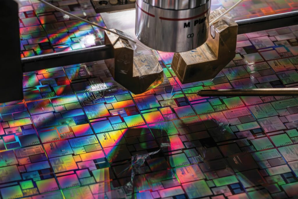
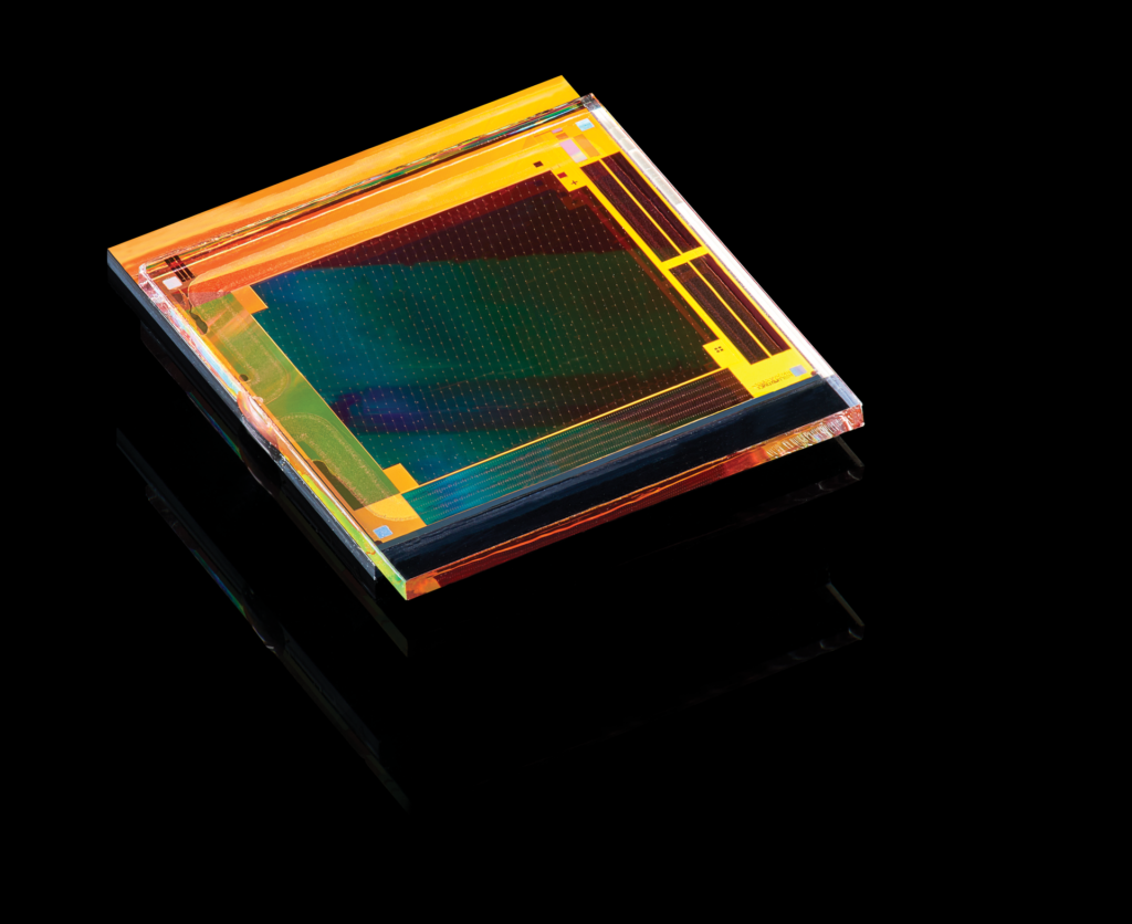
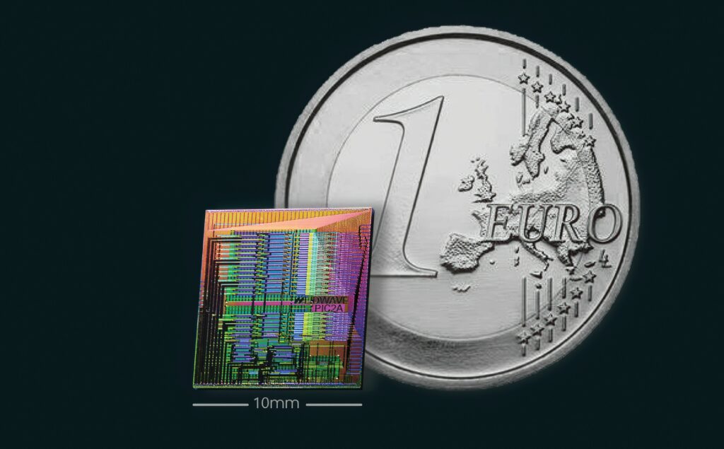
(Image courtesy of CEA-Leti)
Various laser technologies are competing fiercely to reduce the size, weight and cost of sensors for uncrewed systems. Lidar ranging systems are a key technology for long-range sensing for driverless vehicles and autonomous ground vehicles (AGVs), and they are making their way into uncrewed air system and underwater designs.
From miniaturising micro-machined mirror systems to reconfigurable metasurface materials and solid-state flash laser diode architectures, there are many ways for the companies around the world to implement these technologies.
Many are aimed at mapping and surveying applications, often as a separate payload on a UAV to provide detailed data from the air. But integrating the Lidar technology into driverless vehicles, UAVs and underwater robots presents more challenges for reducing size, weight and power consumption, as well as the cost.
For mobile applications, Lidar technology provides instant acquisition of long-range, highly accurate 3D information, enabling the detection of obstacles in complex environments. This is especially important to provide high levels of accuracy to identify the distance to an object, and its size from the time and angle of the reflected light bouncing back from a laser beam over a wide area.
All of this is coming together with a new generation of silicon photonics technology that allows the integration of the optical components on a single chip, from the laser diodes to the optical processing array and optical sensors. This is helping to reduce the size and weight of Lidar designs with a pathway to high-volume production to reduce the cost.
Lidar technology was used back in 1971 by NASA for a lunar Laser Ranging RetroReflector (LRRR) in Apollo 15 to map the moon’s surface, which later extended its use in the spacecraft bound for Mars and Mercury.
However, the laser technology has to be combined with high-performance processing to produce the real-time point cloud that can be used for sensing and control algorithms.
A typical Lidar system comprises a scanning laser, a receiver, associated optics, and integrated driver and processor circuits. It collaborates with cameras, sensors, and the position and navigation system.
Lidar types
Recent trends have seen a growing convergence on vertical-cavity surface-emitting laser (VCSEL) and anti-reflective VCSEL (AR-VCSEL) based solutions.
Lidar for autonomous vehicles falls into two main categories: primary Lidar, responsible for long-range forward perception; and supplementary Lidar, used for peripheral environment sensing around a vehicle. These can be used to provide 360° omnidirectional sensing, eliminating blind spots. The required detection range for primary Lidar varies globally from 150 m to 350 m. This is influenced by the vehicle speed limits, the targeted level of driving automation and regional regulations.
Based on the detection method, Lidar technology can be classified into two types: frequency modulated continuous wave (FMCW) and time of flight (ToF).
(Image courtesy of Vertilite)
FMCW mixes returned light with frequency-modulated transmitted light to determine the distance and velocity of a moving object. Meanwhile, ToF determines the distance by calculating the time interval between the emitted pulse and the returned pulse. ToF is also the earliest technology used for Lidar such as the LRRR used by NASA in the aforementioned 1971 Moon mission.
Currently, most Lidar manufacturers are using ToF technology due to its simplicity and lower cost. This combines separate LED lasers with a modulator, which can be a mirror or a metasurface; a material with a structure small enough to manipulate light (described below).
The 1550 nm laser used for telecoms optical fibre systems also provides long-distance Lidar with eye safety. While this contributes detection range and resolution, it faces significant challenges related to the high cost of the lasers and detectors built with indium gallium arsenide (InGaAs), as well as heat dissipation issues due to high power, reliability risk and large physical dimensions.
The 1550 nm Lidar sensors can be mounted behind a vehicle’s windshield. They consistently deliver high-resolution detection of hard-to-perceive black vehicles at a distance of over 300 m, while maintaining a 120° x 20° overall field of view (FoV).
This provides several advantages, including lower overall system costs and a cleaner roofline. The sensors have also accurately detected vehicles and other objects on busy freeways at distances beyond one kilometre.
For mid- to long-range implementations, 905 nm EEL (edge emitting laser) can provide a more economical approach in cost and size. Triple-junction EEL devices are known for their temperature stability and have been combined with MEMS mirrors in first-generation hybrid Lidar systems. The range of 905 nm Lidar has been significantly improved in recent years, thanks to the higher-efficiency, mainstream, single-photon avalanche detector (SPAD) devices.
There are three types of commercial automotive Lidar based on the scanning method: mechanical Lidar (involving the movement of lasers, lenses and sensors); hybrid solid-state Lidar (in which only the scanning MEMS/mirror moves); and all-solid-state Lidar (with no mechanical movements, as the scanning beam is controlled electrically).
Other scanning methods include optical phase arrays (OPA), focal plane switch array, acousto-optic beam steering, planar lens, MEMS-integrated metasurfaces, beam steering metasurfaces and liquid crystal metasurface (LCM) devices. OPA and LCM are commercially available, but have yet to achieve mass production, while others are still in the research phase.
Metasurface potential
One promising technology is the beam-steering metasurface. This is a programmable optical semiconductor technology, which can be used for automotive Lidar systems, AGVs with a 25 m range and a 10 Hz sensing frame rate, as well as for UAVs.
One metasurface uses liquid crystals as those structures, which can be reconfigured to change the phase of the light beams to steer them. This beam steering allows the light to sweep the area in front of a vehicle.
This technology was designed and optimised with a cloud-based simulation tool that provides an efficient method for predicting the anisotropic permittivity and the response of liquid crystal at the nanometre scale.
(Image courtesy of Lumotive)
The primary challenge when simulating performance was the requirement to model large-area optics while including the nanoscale features representing variations in the standard CMOS chip-making process. Specifically, the modelling needed to capture optical properties at a macro-scale length of over 100 µm with nanoscale precision of under 5 nm.
This requirement created significant computational complexity, requiring a cloud-based tool that can provide the necessary compute power.
The metasurface can be paired with the latest laser diodes. Recent discrete laser diodes have an optical power of 1 kW for detecting objects at greater distances with more accuracy. There is a need for laser diodes that serve as light sources to achieve high kW-level output while allowing multiple light sources to emit light at close intervals.
A surface-mounted infrared laser diode can provide eight channels at 125 W each to provide 1 kW of power for Lidar applications that use 3D ToF systems for spatial recognition. Such an LED design uses eight emission areas per element, each 300 µm wide, which are installed on a submount fixed to a high heat-dissipation substrate.
With such high power, packaging is key to the Lidar design. The emitting surface can incorporate a clear glass cap to eliminate the risk of light scattering caused by scratches, which can happen during the dicing process when the LEDs are cut, which tends to occur with resin-encapsulated products.
This will ensure a high beam quality, providing uniform emission intensity across the emission width, as well as a low wavelength temperature dependence of 0.1 nm/°C (vs 0.26 to 0.28 nm/°C for standard products).
The eight-channel array is designed with a configuration that narrows the regions of reduced emission intensity between channels, while the bandpass filter minimises the effects of ambient light noise from the sun and other sources, contributing to long-distance detection and high-definition Lidar.
The metasurface and LED laser can be combined with commercial SPAD detectors. This has the sensitivity to be used for long-range Lidar in a robotaxi or a self-driving truck.
Hybrid solid-state Lidar manufacturers initially combined a point source such as a 1550 nm fibre laser or 905 nm EEL with a 2D MEMS or mirrors. One example of a hybrid system is a solid-state source electrically scanning in one direction and a 1D polygon/mirror scanning in the other. This solid-state source consists of either a series of small VCSEL/AR-VCSEL chips or a chain of VCSEL/AR-VCSEL narrow arrays. This design eliminates the need for precise alignment between the lasers and the MEMS mirror.
EEL-based Lidars usually have a range limit of 200 m, while AR-VSCEL-based Lidars with the current six-junction technology already surpass this range, and advancements to eight to 10 junctions promise to push it towards 300-400 m. Additionally, the generally lower cost of VCSELs compared with EELs suggests AR-VCSELs may hold significant long-term advantages.
Camera hybrid
The laser technology is also being combined with a camera sensor. Aligning the optical axis of the laser system and an optical camera allows the real-time acquisition of parallax-free superimposed data, which was previously unattainable through sensor-fusion algorithms.
Typically, Lidar is used with cameras to identify objects more accurately, but parallax in the data from the various units often caused delays from calibration between the sensors. The camera-Lidar fusion approach integrates the camera and high-resolution Lidar in a single unit for parallax-free, real-time data integration, ensuring efficient and accurate results. This enables the real-time integration of camera image data and Lidar distance data for advanced object recognition.
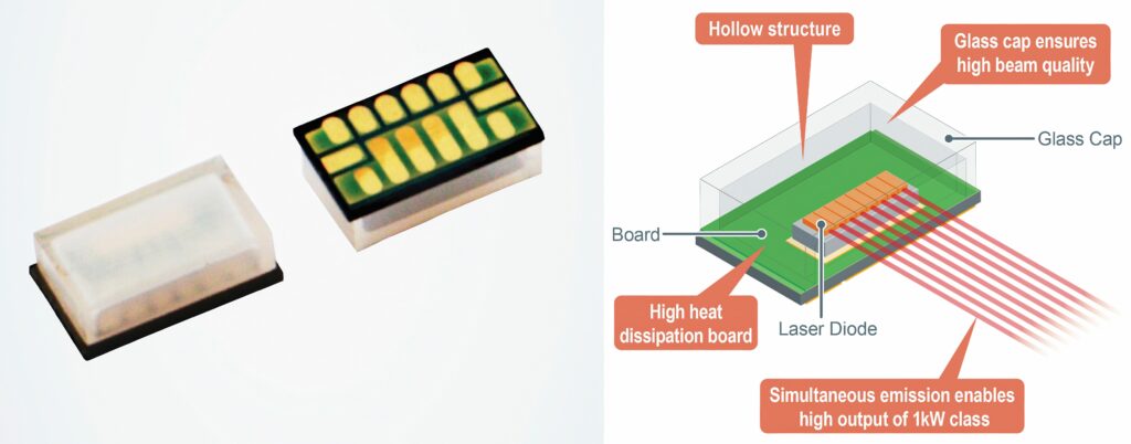
(Image courtesy of Rohm)
Lidar can recognise small obstacles over long distances by increasing the density of laser beams emitted, thereby improving resolution and accuracy. This combination sensor has an irradiation density of 0.045° with a custom scanning technology taken from laser printers. This can detect a 30 cm falling object at a distance of 100 m.
In Lidar, a MEMS mirror or motor is required to irradiate laser light over a wide, high-density area. However, MEMS mirrors typically have lower resolution and motors tend to wear out quickly.
One company’s new integrated sensor provides higher resolution than motor-based systems and greater durability than conventional MEMS mirrors.
A proprietary MEMS mirror, developed with that supplier’s advanced manufacturing and ceramic package technologies, and high-resolution laser-scanning technology, supports high-precision sensing for various industries, including autonomous vehicles, ships, heavy machinery, and more.
Solid state Lidar
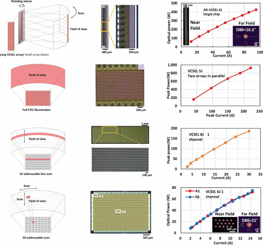
An all-solid-state Lidar eliminates moving parts and replaces mechanical scanning with electrical scanning. Among the commercially viable system designs are a VCSEL source with defocus lenses for flash illumination and 1D/2D addressable VCSEL with defocus lenses.
Additional options include VCSEL/EEL with a metasurface and a FMCW EEL with optical array.
Medium- to long-distance Lidars use an array of addressable VCSEL lasers, which can be scanned to illuminate the area in front of a vehicle. A 2D VCSEL array matrix allows individual control of both anodes and cathodes of the VCSEL laser diodes, providing more flexibility in the illumination strategies.
The metal electrodes add complexity to the fabrication, however, and it faces slightly more challenges compared with the 1D approach.
(Image courtesy of Zhejiang University)
Higher peak power enables greater signal-to-noise ratios and longer detection ranges for Lidar. Having more junctions ensures a higher external quantum efficiency, directly proportional to the junction count.
This results in a higher power density, while driving current, and a greater power conversion efficiency for the same optical power. Existing VCSEL-based Lidars typically have five to six junctions, doubling every 18 months.
Researchers have experimentally demonstrated small-divergence AR-VCSELs up to 14 junctions and, theoretically, there is no upper limit for the number of junctions. However, in practical terms, incorporating more junctions may present challenges in terms of thick epitaxial growth, high aspect ratio trench/mesa etching and coating in fabrication, and reliability concerns at higher power density and material stress.
Reliability
To ensure the reliable operation of Lidar throughout a vehicle’s lifetime, the lasers must pass the automobile standard reliability test, AEC-Q102. This testing includes a high-temperature operating lifetime (HTOL) of 1000 h, HTOL under 85 C and an 85% humidity environment of 1000 h, a low-temperature operating lifetime of 500 h, powered/unpowered temperature cycling, a harmful gas test, dew test and an electrostatic discharge (ESD) test.
While AEC-Q102 is the basic reliability standard for VCSELs used in automotive Lidar, every manufacturer sets its own standard, which is normally higher and includes rigorous requirements for the failure in time (FIT) rate – the number of failures expected in one billion device hours of operation.
AR-VCSEL array chips can survive the 6000 h HTOL test, well above the AEC-Q102 requirement and represent over 300 years of use in the field.
In addition to the long-term ageing study, tens of thousands of AR-VCSEL array chips have been subjected to the FIT study.
Although the higher power-density requirement in future Lidar systems to provide higher range sensing may add stress to the lifetime of AR-VCSEL, the tests show sufficient endurability.
FMCW tech
FMCW technology combined with OPA is seen as promising for the all-solid-state Lidar. FMCW takes advantage of the laser source coherence, granting a high immunity to ambient light of the 3D imaging system.
Inertia-less beam steering based on silicon-integrated OPA is an essential component for the solid-state Lidar. High-performance, integrated OPA should have a wide field of view and a small beam divergence.
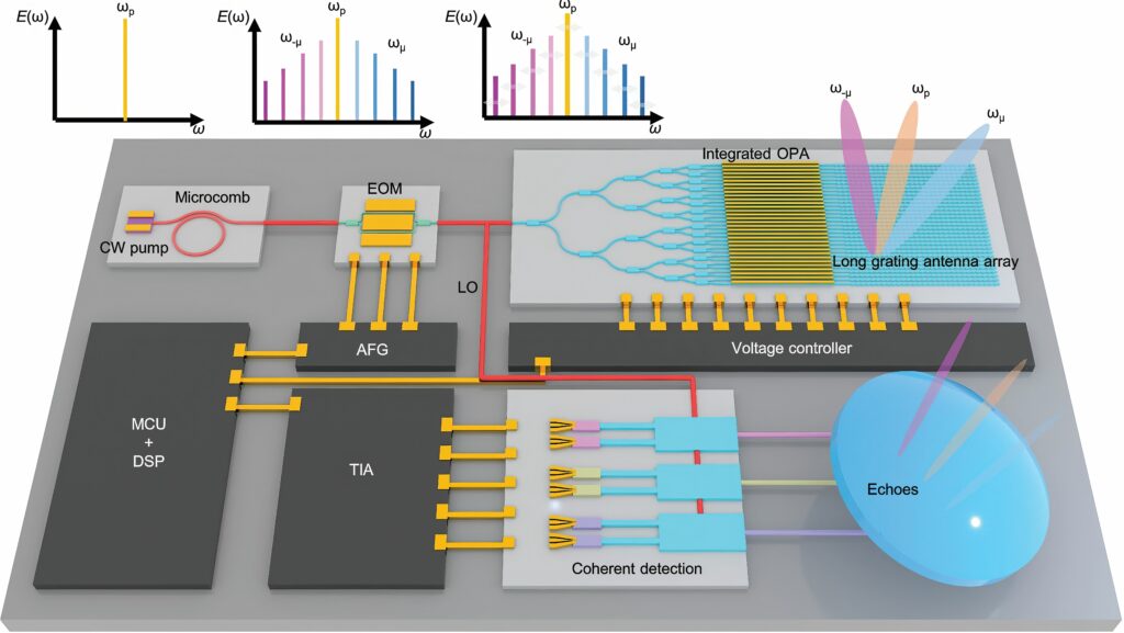
A silicon integrated OPA combined with an optical-frequency microcomb has been developed experimentally for a parallel Lidar system with four beams, each with a separate phase, to increase the FoV.
(Image courtesy of Lidwave)
The beam divergence and multi-beam quality are challenging to implement, but they are essential for producing parallel beams, with each carrying distinct wavelength information. An ultra-long, optical grating antenna with a low coupling constant and a low phase error is usually required for a small divergence.
A millimetre-scale antenna can be implemented with small etching corrugations of silicon waveguide or assisted with the multi-layer material, such as silicon nitride. However, it demands high lithography precision, etching precision or heterogeneous material growth, which is complex to make and has a high cost.
In the detection terminal, the coherent method is usually superior to the other implementations in the circumstance of low visibility or high background light. One system has been developed with a measured beam divergence of around 0.037° with the long optical grating antenna, which is consistent with the comb tooth spacing (101.3 GHz). The signals from the multiple comb tooth, carrying distinct wavelength information, are output and steered by the integrated OPA.
The all-solid-state parallel Lidar has been demonstrated with the FMCW method for 3D ranging. External modulation is used to obtain the parallel-frequency, modulated, multi-wavelength laser source with only one pump laser.
Other designs improve the optics of FMCW flash Lidar by integrating critical components into a single device, opening up opportunities for compact and efficient systems for autonomous driving. This integrated version of the illumination optics of an FMCW flash Lidar is a first step towards a fully integrated Lidar sensor that cuts costs and boosts performance.
Heterodyne detection consists of separating and then recombining a time-varying frequency laser beam. The split beam illuminating the scene undergoes a delay compared with the reference beam, resulting in a beating signal formation on the detector after recombination.
Pairing FMCW with a flash illumination (simultaneous illumination of the whole scene) instead of a scanning technique offers potential benefits such as a higher frame rate due to parallel detection and the absence of moving parts.
Full integration of this system would reduce fabrication costs, and increase scalability and compactness. An integrated design for the emission optics on a photonic chip is responsible for both functions of beam separation and scene illumination. An apodized grating coupler with few periods provides a large horizontal and vertical illumination field, homogeneous far-field profile and emission perpendicular to the chip.
The parameters of the grating coupler are numerically optimised to maximise simulated performances in the near infrared. The beam separation ratio can also be adjusted with the grating coupler efficiency to gather the two optical functions in one component, which is not possible with bulk optics.
Another technology, called finite coherent ranging, integrates the entire Lidar system, including lasers, amplifiers and detectors, on a single chip. This design uses what is called a monostatic technique, where transmitting and receiving happen from the same pixel.
This reduces manufacturing complexity significantly, eliminating the need for precise calibration and allowing for streamlined, large-scale production.
This provides a configurable FoV of up to 100° x 40° with a 0.02° accuracy, both horizontally and vertically, and a range of up to 600 m, which is significant with a frame rate of 5-30 FPS. The system can also detect the velocity of a moving object with an accuracy of 0.05 kph (10 mm/s). All of this highlights the focus on how FMCW can be used in more integrated devices to reduce the size and power consumption of Lidar sensors.
Underwater scanning
Lidar can even be used underwater. The latest patents use scanning techniques to monitor the water temperature around human-made and natural structures. A single sensor can create a 3D image and a 3D water temperature map of the area at the same time.
The latter can be used to monitor the temperature at the top of a well plug or internal pipe-sealing plug, for example, as part of an abandonment operation, during reservoir stimulation/carbon reinjection or during reservoir lifting operations. Other applications include the study of deepsea thermal vent fields or remote temperature monitoring during dry cask storage operations for spent nuclear fuel.
The same sensor can be used to measure the amplitude and frequency of vibrations to evaluate structural integrity, including measuring and calculating vibration modes of the structure.
This can also be used for exact placement of objects in an underwater environment. This can project a visible target on the seabed to aid with accurate placement of the equipment, and using the optical system on an UUV can monitor its location in reference to other underwater structures and features for more accurate positioning.
Future trends
In the short term, the rapid replacement of 1550 nm fibre lasers with 905 nm or 940 nm VCSELs in the next few years will help to reduce costs. A lower-cost alternative for 1550 nm lasers is InP-based, high-power EELs, although these are still more expensive than GaAs-based lasers.
The ongoing development of Lidar systems is a balance of distance and cost. The 200–300 m distance requirement is increasingly being met, and the further increase in performance allows engineering tradeoff for reducing the cost.
Over the past decade, Lidar costs have plummeted from over $10,000 to the current range of $500 to $1,000. This downward trend is expected to continue, potentially reaching the $100 range in the coming years as production volumes increase and technologies such as silicon photonics become mainstream.
Acknowledgements
With thanks to Dong Liang at Vertilite, Jingye Chen at Zhejiang University and Paul Camus at CEA-Leti.
UPCOMING EVENTS


