


Launchpoint EPS HPS400
Getting the technology mix right is paramount in designing hybrid-electric powertrains, as Rory Jackson finds out
The sum of its parts
As advancements in electric aviation outpace those in battery energy density, new designs for lightweight, hybrid-electric powertrains are gaining attention for combining the specific energy of liquid fuel with the specific power of batteries, and the flexibility and controllability of electric motors.
LaunchPoint Electric Propulsion Solutions (LaunchPoint EPS, or just LaunchPoint) understands well the strengths and weaknesses of the many different technologies across hybrid powertrains. Though spun out as a business entity recently, in 2020, it carries 32 years of expertise and research from its parent company, LaunchPoint Technologies (LPT).
“LPT was originally founded in 1992 as a sort of think-tank, then called Magnetic Moments, by the trio of Brad Paden [chief scientist], Dave Paden [principal mechanical engineer] and their father, Al, who was a Raytheon engineer,” says LaunchPoint chief technology officer Michael Ricci.
Critical in that project were Halbach arrays: permanent magnet assemblies configured with enhanced magnetic flux (and hence a strengthened magnetic field) at one side, and almost completely cancelled flux (with no stray field) on the other, as well as not needing back iron in the rotor.
Geoff Long (now aircraft chief engineer at Wisk) joined LPT in 2008, and proposed putting the array design from the maglev project into a circle to create a permanent magnet rotor, making for a functioning Halbach array e-motor. This configuration makes a short, flat, pancake e-motor, also known as an axial-flux motor.
After Long departed, Ricci began researching applications for the e-motor, quickly looking beyond motor-prop drives as axial-flux motors often block propeller airflow with their wide diameters. Instead, through some workshops around 2012, Ricci and his colleagues came upon a NASA project aimed at making a hybrid-electric powertrain for a UAV, intended to achieve greater than 16-hour flight endurances.

“The theory of their powertrain concept looked great, but despite being brilliant aeronautical engineers, they had no idea of the electrical, magnetic and mechanical technical details required to actually implement it. We realised there were likely masses of similar aero engineers who hadn’t experienced firsthand that it takes way more than just sticking an alternator onto an engine to create an effective hybrid powertrain,” Ricci says.
“We also then realised that axial-flux motors could make great generators. There’s little, if any, airflow for them to block, and their incredibly thin cross-sections let them ride right on the crankshaft without separate bearings. Everyone else was doing generators with shaft couplings to the engine, which were heavy, prone to breakage due to the pulsing power-strokes and created numerous other problems.”
After agreeing with his colleagues that they should build a generator set (Genset) based on their Halbach motor design, LPT sought and won Small Business Innovation Research (SBIR) funding from NASA to build a prototype.
“Simultaneously, the US Navy wanted our technology for an electric helicopter’s tail rotor, replacing the transmission shaft traditionally running turbine to tail, and our proposed design consisted of two 40 kW Halbach generators stacked together to power the associated motor. Designing such a machine was fine, but I knew it would take a lot of high-powered testing,” Ricci recalls.
LPT hence bought a Rotax engine as a prime-mover test device to get the US Navy their 40 kW e-generator, and also create a prototype, 40 kW Genset that satisfied the terms of the SBIR.
That prototype has been iterated and optimised in the subsequent 10 years as the HPS400 Genset, to date the most powerful of LaunchPoint EPS’s complete solutions for electrified aircraft power.
The HPS400 system comes in either a ‘passive’ configuration, weighing 69 kg and outputting electricity over a 215 VDC bus (104 V DC is also available), and an ‘active’ configuration, which weighs 64 kg. In addition to sharing a peak power output of 40 kW, both configurations have a SFC of 566 g/kWh at their maximum continuous power output of 35 kW (achieved at 6000 rpm crankshaft speed).
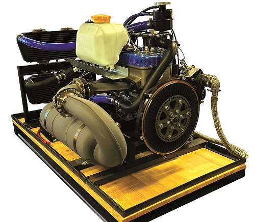
The system is built around a Rotax 582 liquid-cooled two-stroke, being a widely documented and well understood engine, with the components and instructions for maintenance easy to find. We will focus henceforth on LaunchPoint’s unique componentry around this engine and the steps taken by the California-based company to engineer its vision of the ideal hybrid powertrain.
Passive vs active
Together, the Rotax 582 and the Halbach motor-generator, LaunchPoint’s DHA120 product, form the core of the HPS400. The 48 kW Rotax engine weighs 41.4 kg, making it the heaviest component in the powertrain, while the DHA120 weighs 4.5 kg.
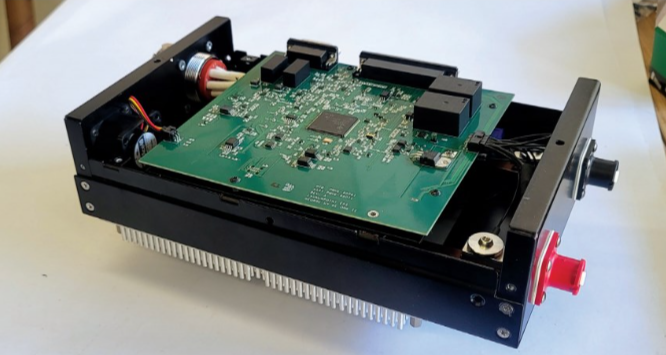
The remaining 17 kg or 22 kg (depending on whether the passive or active HPS400 configuration is chosen) is taken up by power electronics, wiring harnesses, and assorted systems for starting, cooling and control.
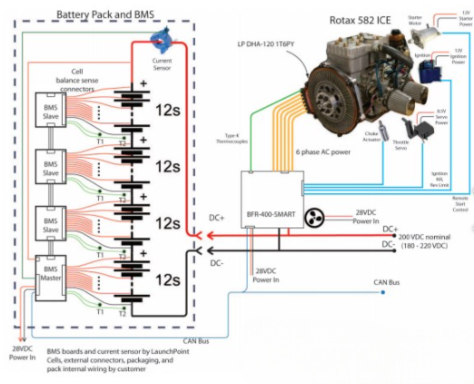
LaunchPoint’s Power Management Unit (PMU) is the control authority for the powertrain, commanding the Rotax engine’s ECU, the DHA120’s controller, and a BMS via a CAN bus, using LaunchPoint’s communication protocol originally developed for a project with NASA.
Depending on the voltage and power electronics configuration, the DHA120 generator can be a three-, six- or 12-phase configuration. Through the PMU and power electronics, the DHA120’s AC output is rectified into one or more DC channels and merged with the output of the end-user’s application-specific DC bus batteries.
“The passive configuration is a one-way powertrain, with just high-power diodes in the PMU that rectify the DHA120 generator output into DC, and a separate starter motor supplied to start the engine,” Ricci says.
“In the active system, we provide a bi-directional inverter-controller, built using silicon-carbide [SiC] MOSFETS to drive the DHA120 as a motor, so that it can start the engine and also provide shaft power in parallel hybrid configurations, where the e-machine can boost engine shaft power instead of generating electricity.”
The passive system is electronically simpler and less pricey, but requires a separate starter motor and starter battery. In contrast, the active system power electronics weigh 5 kg more, but a separate starter motor and battery are not required. The active system also achieves greater power efficiency and transient performance than the passive system.
LaunchPoint recommends the passive configuration for continuously hovering applications, like multirotors with a constant high-power requirement, whereas the active configuration provides best value to VTOL-transitioning aircraft to provide full power for hover, but then throttle back the engine’s most efficient operating point at 25-50% power in cruise.
The active system also works well with a parallel, hybrid-type system that may feature a very large pusher or tractor propeller on the engine shaft, outward of the DHA120 starter-generator. In this case, the motor-generator functions either to provide hover power for the separate electric lift motors or to provide an additional, electric boost to the main shaft for climb and high-performance peaks.
Rotax 582 aviation engine
LaunchPoint has modified the Rotax 582 with some key components. The first is a high-performance, metal-geared, industrial servo from Futaba to control the throttle, as the engine was originally designed for ultralight aircraft, and hence comes as standard with manual throttle and cable for the pilot to use.
“Through that servo, the PMU sets the throttle plate to the starting position, cranks the engine, stabilises rpm and adjusts the throttle as the loads vary, all quite transparently,” Ricci says.
The starter motor was similarly modified to accept electronic control from the PMU, rather than manual control from a pilot’s switch.
In addition to changes made for control, various other changes were made to the thermal management system to accommodate the reduced ambient airflow found in hovering flight conditions.

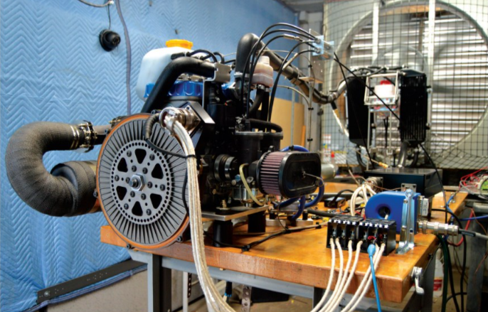
For example, a heat shield was installed between the exhaust manifold and the oil tank (to prevent the latter from melting after 1.5 hours of continuous running in hover), while a second radiator and two 30 W fans – one per radiator – were integrated into the powertrain’s cooling loop. While the 582 is liquid-cooled, it was designed for fixed-wing aircraft, where normally the airflow from forward flight would dissipate heat from the single, standard radiator.
“We’re designing the HPS400 for aircraft that will often hover, without that tremendous cooling airflow from fixed-wing flight – and aircraft reciprocating engines are almost never designed to run at full power while stationary,” Ricci notes. “We tried different combinations of thermal management solutions, including automotive aluminium radiators, and eventually doubled up the Rotax radiators and added fans to ensure proper cooling.”
Going forwards, LaunchPoint anticipates that its radiators will be customised for end-users, especially as they better understand their case-specific thermal requirements, and request units in volumes sufficient to justify the expense of a custom radiator design.
“Honestly, an aviation engine isn’t even necessarily the optimal engine for use in a Genset, because our generators want to run fast and fixed-wing aircraft engines want to run slowly. Theoretically, the DHA120 could run at 55 kW if spun at 9000 rpm,” Ricci adds.
“But the problem then is that the ideal engine for us might be something like a high-revving snowmobile gasoline engine – something that runs most efficiently near its redline – but those engines aren’t made by companies with a pedigree in aircraft engine optimisation.”
LaunchPoint is now qualifying and characterising some non-aircraft engines to modify them for aviation-critical requirements such as weight optimisation, direct drive (or at least the absence of transmissions that could obstruct mounting of the generator) and automatic digital control. The company is also open to collaboration with UAV engine companies capable of creating an ICE suited to high-speed, hybrid applications.
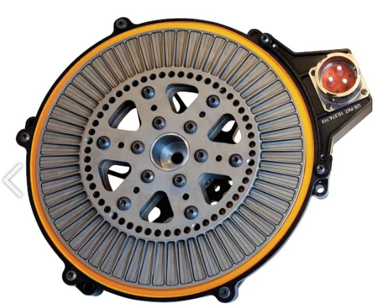
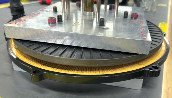
DHA120 axial-flux electric motor
The DHA120 measures 317.5 mm in diameter, 45 mm in length and is constructed with dual Halbach array rotors sandwiching an ironless stator, with 60 poles per rotor and stator.
“Our ironless rotor and stator give our motor-generator such low inductance that we can push pole counts and frequencies much higher than conventional systems, and that helps make our electric machine lighter because we’ve got lots of thin poles, rather than a few really big, heavy poles,” Ricci says. “It also helps the voltage to stay very well regulated as the load changes.”
While the machine is built around 30 pole pairs, each pole in the rotor is a section of the Halbach array, constructed of three permanent magnets: one upper part and two diagonal parts either side of it, making for 180 magnets per rotor, and 360 per DHA120.
The air gaps between rotor and stator are typically 1 mm, although they can be adjusted to specify the voltage for different applications or allow more clearance for axial movement in the bearing system. Unlike radial-flux motors, where the air gap is fixed, LaunchPoint’s rotors can simply be moved apart along the stator shaft (or crankshaft) if a reduced bus voltage or increased shaft speed is required.
“When we started, people warned us about crankshaft end play – when the crankshaft slides in its bearing with very slight longitudinal movements, not enough to cause piston scraping front or back, but enough to make engineers think the rotor and stator were going to touch,” Ricci recalls.
“We’ve designed the axial gap in the generators to be larger than the crankshaft end play in the engines we’ve used in our HPS400s and other Genset products. We’ve tested and found that the engines exhibit acceptable end-play, even when we cycle them to the limit of their TBOs. But if someone wants a different engine that shows some end-play, we can space out the rotors and stator to compensate, albeit with some voltage and maybe performance loss. There is one right now, for instance, which we’ve set for 2 mm air gaps, where maximum continuous power drops to 30 kW.”
Another advantage given of LaunchPoint’s axial-flux design is the self-cooling ability in that air gap. As the rotors spin, they entrain air through machined holes on the inner part of the motor, inducing it to spin and blow outwards at high pressure between the rotors and stator with a circular motion (discussed further below).
“Integrating a high number of very thin poles is also the key to unlocking six-phase power; conventional, slotted designs are limited to three-phase AC because they can’t make their poles narrow enough, and they’re made with iron and steel that drives up the inductance and prevent use of high pole counts,” Ricci explains.
“With six-phase, you get twice as many current pulses in your sinusoidal waveform output, so the valleys between are smaller, and you get much smoother, cleaner power output and better voltage regulation. In legacy aircraft with three-phase buses, electric engineers would install a big, heavy transformer to artificially shift three of the phases to make a six-phase output, with really large, powerful, 12-pulse rectifiers called ‘transformer rectifier units’ [TRUs] to handle the voltage and current ripple.
“We get the advantage of 12-pulse rectification, without needing a transformer, largely thanks to our unique, ironless design. Six-phase does entail twice as many measurements as three-phase, and current and voltage sensors don’t come for free, but once you’ve designed for it in your electric machine, it is not any harder to engineer or manufacture than our three-phase configurations.”
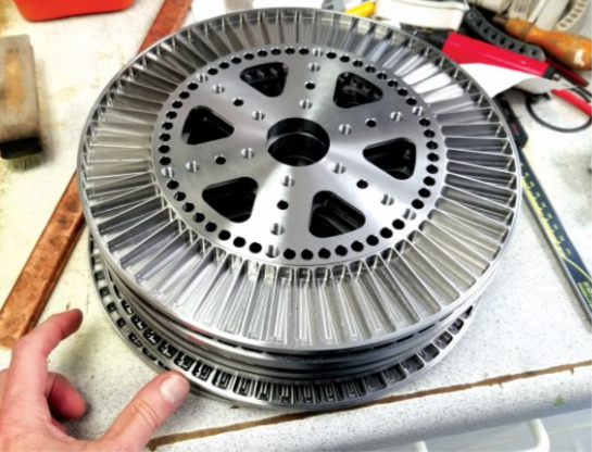
Dual Halbach array rotor
A radial-flux Halbach motor with an outrunner (internal stator, external rotor) design inherently self-confines all of its magnetic flux within the bore, making it an increasingly popular motor configuration.
Given the axial-flux nature of LaunchPoint’s motor design, however, combined with the absence of iron in its stator, a dual-rotor design was necessary to confine the flux within the space occupied by the stator (and a single rotor design would have meant that the stator windings only received around half the magnetic field from the permanent magnets).
Neodymium iron boron permanent magnets are selected to maximise the magnetic strength and hence power efficiency of the rotors, including grades such as ND48, ND45 and ND52. LaunchPoint can also work with high-temperature neodymium magnets or even samarium-cobalt magnets for applications where an extremely hot environment will tax the motor’s self-cooling, and DoD-approved (DFARS compliant) magnets if the mission requires it and the ensuing price can be covered.
“Whichever magnet we’re using, the manufacturer cuts them to our specified shapes; then we bond them together in the aforementioned groups of magnets for the Halbach array, and then we epoxy them into our rotor plates,” Ricci says.
“Those plates are machine-cut from titanium, including the pockets that the magnets insert into, but we don’t machine all the way through the plate. We leave a ‘floor’, which faces the air gap, and means the magnets can’t come unbonded, fly into the gap and jam the motor. That’s a huge reliability aid: even if the epoxy somehow dissolved, some of the magnets might slide away from the air gap a little, meaning a tiny loss of power, but the motor would keep working, with no critical loss of power mid-flight.”
In some applications, LaunchPoint will also cut thin, titanium discs and weld them onto the outer face of each rotor, hermetically sealing the magnets against coming loose or into contact with anything that could harm them or the epoxy.
Titanium has been chosen for high strength-to-weight and fatigue properties. “When a cylinder fires in a piston engine there is an incredible momentary torque pulse,” Ricci says.
“The peak torque can be 15 times the average torque in a single cylinder engine – so if you design an electric motor-generator for 10 Nm of average engine torque, you need it to withstand peaks of 150 Nm when attached to a piston engine. An aluminium rotor structure would fatigue and break off after a while; titanium wins out there.”
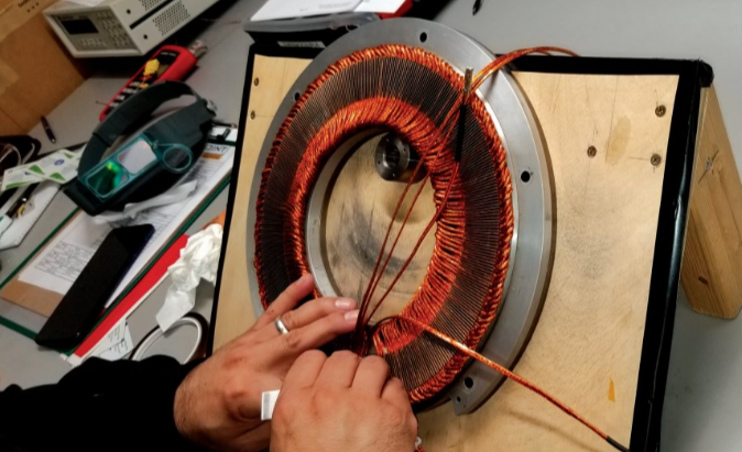
Ironless stator
Historically, ironless stators have been costly to manufacture, and challenging to produce and customise with copper fill factors above 20%, but their advantages, such as high weight efficiency, minimised thermal and eddy current losses, and smoother and quieter power output with no core iron-derived cogging have driven consistent interest in ironless designs, particularly for high-speed applications.
LaunchPoint’s ironless stator design is currently produced by initially hand-winding the copper into the desired form (a key step towards customising and optimising copper fill) and then over-moulding it with a thermally conductive epoxy resin, which, once cured, is fastened to an outer, metallic aluminium ring.
Unlike conventionally hand-wound stators, in which production engineers must pack wire into slotted structures in complex 3D geometries, LaunchPoint’s process largely just involves laying wire out into the desired form factor on a flat work surface. Hence, the winding processes will be easily automated via a robot with just two degrees of freedom (once production volumes hit about 1000 units per year and justify doing so).
“We use a full-pitch wave winding with finely stranded litz wire, in which the individual strands are insulated to break up eddy currents by preventing them from circulating strand-to-strand. It is quite known in the art of ironless designs now that you really need to opt for litz wire in your windings,” Ricci says.
While much of the specifics of the process are proprietary, LaunchPoint nods towards New England Wire Technology as its supplier of litz wire and a key source of consultation on the winding optimisation.
“Beyond that, the proprietary resin about the copper is key to both heat removal and structural strength,” Ricci says. “Motor torque is directly linked to two factors – the current in the winding and the magnetic field from the rotor. The Halbach array maximises magnetic field, and the winding design maximises the stator current density.
“Operating at maximum torque and maximum stator current density inevitably drives up heat in the copper, to the point that the stator runs up to 200 C. Finding a resin that could operate at such temperatures was a big challenge, but we’ve found and settled on a material that is rated to 220 C peak operating temperatures.
“The resin is applied using a vacuum-based process similar to compression moulding. Once cured, it exhibits enough stiffness for surviving the vibration and torque pulses from the engine, and high thermal conductivity for the forced-air cooling to dissipate the heat extracted from the copper bundles.”
SiC-powered motor control
As the MOSFETS or IGBTs in a motor controller switch on and off, the high-voltage energy to the motor is being turned on and off to alternate the current up and down in a sinusoidal waveform. The gradient of the waveform relates to the motor inductance: when the transistors switch on, energy is stored in the inductance, and when they switch off, energy comes out of that inductance. In essence, motor inductance functions like piston engine flywheels, smoothing the electrical power pulses from the motor controller’s toggling switches and enabling smooth torque from the motor.
“With our very low-inductance motor comes the issue of a tiny ‘flywheel’. With high energy or power output there’s a risk of creating huge current ripples. To mitigate that, we need transistors that turn on and off much faster than in the average e-motor to get smaller pulses,” Ricci explains.
“A conventional motor drive turns on and off 20,000 times per second, but SiC MOSFETS can do 60,000-80,000 Hz. That makes our AC pulses three to four times smaller than conventional. It is like going from a V8 engine design to a V12 or V14 engine, just in terms of our power converter and MOSFETs.”
The active system PMU contains SiC MOSFETS arranged to invert the DC input to an AC output or vice versa. A plethora of current and voltage sensors enable close feedback at high frequencies (though sensorless operation is available on request), and gate drivers with built-in desaturation protection are selected to help keep the system safe against shorting.
A high-end DSP from Texas Instruments (TI) used in the PMU embeds the motor control logic; the selection of a microprocessor capable of keeping up with the SiC’s switching speeds having been vital to LaunchPoint.
“We have really optimised our code to run our control loops at 50 kHz, which is a lot faster than most motor-generator controllers, but gives us fine management of the sine waves. With our high pole counts, we need those high switching frequencies and high-bandwidth, control-loop execution, so highly optimised code and using a costly but quality DSP was critical for making sure each system synergistically worked together,” Ricci notes.
Self-cooling
While different liquid-cooled versions of the DHA120 are available, particularly for high-altitude UAVs flying above 40,000 ft, where insufficient air for cooling is available, all run significantly heavier than the standard, air-cooled version.
Regarding how the 4.5 kg, 40 kW generator is self-cooled via air, Ricci explains: “The flat, spinning surfaces in the air gap function as an impeller via surface friction. If you look into ‘tesla turbines’, those are flat, bladeless discs that spin relative to each other and actually pump water, without needing vanes.”
Historically, metallurgy was not advanced enough in Tesla’s time to engineer tesla turbines effectively, but today’s research is yielding promising results for their use in industrial and medical applications.
In LaunchPoint’s application, the high-speed spinning of the rotor drags air into the rotor-stator gaps by way of surface friction, entering through the gaps in the rotor plate and running in a circular pattern, with centripedal force then driving the air out of the gaps.
“The high speed of the air creates a lot of turbulence, which is perfect for good convection. We get almost liquid-cooling levels of convection inside the air gap,” Ricci says. “And it’s a very small, thin, turbulent boundary layer, so the turbulence doesn’t exert enough force to cause any damage or drag inside the motor.”
The HPS400’s other components, such as the PMU and BMS, do not use any of the motor-generator’s airstream as this would require mounting them on or close to the engine, where huge vibratory or heat hazards would be presented. Instead, their enclosures are designed with heat sinks, and fans where necessary, their placement and mounting throughout the UAV to be optimised between LaunchPoint and each specific customer.
Control systems
The PMU’s DSP covers all motor and engine control functions, plus monitoring and communication with the LaunchPoint BMS. The PMU also contains the engine’s ignition control module, and the company’s CAN bus (based on an earlier protocol used by NASA, since expanded for the integrity and prioritisation requirements of LaunchPoint’s powertrains).
“The CAN protocol is simple, but can have up to 64 of our devices on the same bus, so UAVs needing two generators, two BMS, multiple PMUs working as motor controllers across an airframe, can all share a common bus and work together by monitoring each other’s real-time data,” Ricci says.
Both the passive and active configurations of the HPS400 use similar control algorithms, although the latter naturally has more functions, and more operational and control degrees of freedom. Across both, the PMU essentially runs a power control algorithm, with sensors connected across both PMU and BMS first taking load measurements from the UAV to determine how much power must be supplied (with the battery and powertrain treated by the software as a single, unified power source to the DC bus).
“The PMU then determines how the engine needs to run to generate power per load, with a feedforward algorithm calculating how to get the engine to that output. If, for example, your UAV drops out of cruise to hover mid-air at high power, our generator can certainly go from zero to full torque and power near instantly – ICEs can’t,” Ricci says.
To compensate, the battery supplies an instantaneous output to satisfy the load, the PMU ramps up the engine’s shaft power, the generator turns that into AC, and the PMU then rectifies it into DC to replenish the battery as required by the load.
“When the load drops again, the battery absorbs the excess energy from the generator during the seconds it takes to de-throttle the engine,” Ricci adds. “If the engine tries to over-rev, we can kill the ignition – we have rev limiters in there, like those in high-end sports cars, so multiple points of over-rev protection.”
The PMU also tracks cylinder head temperature (CHT) and exhaust gas temperature (EGT) sensors to govern the fans and liquid pumps connected to the radiators. If the engine overheats, it can alternatively reduce shaft power (without shutting down completely) and increase the battery discharge rate to compensate while the engine cools. LaunchPoint works with customers to size battery packs for at least a few minutes of reserve energy, to allow continued safe flight and landing even if the engine should seize entirely mid-flight.
Future
As of writing, LaunchPoint is working in three principle markets for hybridised and electric powertrain. The first two are large, DoD aircraft integrations and urban air-mobility companies, with projects including motors for high-power pumps and actuators, and radial-flux designs.
The third, and potentially largest for the California-based company, is precision crop-spraying UAVs, where one customer is working with LaunchPoint to achieve extended flight with payloads of 60-100 kg or more, making hybrid power vital for its operations.
“Longer term, those and other industrial UAVs are going to get bigger and bigger, and hybrid powertrains scale up better than they scale down,” Ricci observes. “We don’t know how big we will go, as megawatt piston engines and turbine engines both have their respective difficulties, but a lot of ag-spray drones are coming out with 20 m wingspans and have to cover vast acres.
“They will eventually reach full aircraft size, with 3000-4000 lb MTOWs to carry 500-1000 lb of agricultural product, but for now, we’ll start with UAVs at 60-100 kg payloads, and those will grow as fast as the FAA allows them. Luckily, uncrewed spray flights get clearance waivers quickly, mainly because they fly low, and always within line-of-sight (LOS). And, once there’s a Part 107-style rule for BVLOS flights by big, heavy drones, that is going to open up a huge world of new use-cases for our powertrains.”
Until then, the company has been awarded a Phase One SBIR by AFWERX, a directorate of the US Air Force Research Laboratory, to develop a modular, hybrid Genset with up to three DHA120-like systems working in parallel to power a Group 4 or 5 UAS (defined as having MTOWs of over 1,320 lb, or 598 kg).
Between that, the burgeoning tide of agricultural UASs, and its other end-users, one can expect LaunchPoint EPS to be kept very busy in the years ahead.
Key specifications
HPS400
- Hybrid-electric
- Complete system weight: 69 kg active configuration, 64 kg passive configuration
- Bus voltage: 420 V DC or 210 V DC active configuration; 210 V DC or 104 V DC passive configuration
- Maximum power: 40 kW
- Maximum continuous power: 35 kW at 6500 rpm
- Specific fuel consumption: 566 g/kWh at 35 kW
Rotax 582 engine
- Two-stroke
- Inline two-cylinder
- Spark-ignited
- Liquid-cooled
- Oil-injected
- Dry weight: 41.4 kg
- Displacement: 580.7 cc
- Maximum power: 48 kW (64.4 hp) at 6500 rpm
DHA120
- Permanent magnet synchronous motor-generator
- Axial-flux
- Dual Halbach array rotors
- Ironless stator
- Neodymium iron boron permanent magnets
- Litz wire windings
- Passively air-cooled
- Weight: 4.5 kg
- Diameter: 317.5 mm
- Length: 45 mm
Key suppliers
- Bearings: SKF
- Digital signal processors: Texas Instruments
- Litz wire: New England Wire Technologies
- Radiators: Rotax
- Servos: Futaba
- SiC transistors: Wolfspeed
- Current sensors: LEM
- Heat sinks: Cool Innovations
- Connectors: Amphenol
UPCOMING EVENTS


