


Jetoptera FTC-250
(All images: Jetoptera)
The fluid dynamic
A novel fluidic propulsion system is key to this company’s punchy contenders for the fast-growing cargo drone and air taxi markets. Rory Jackson investigates and unpacks it
Around seven to 10 years ago, the aviation industry experienced rapid growth in the number of new eVTOL and eSTOL aircraft companies, each making bold claims over what their electric air vehicles could accomplish entirely on battery energy.
And while none among the informed disagree that humanity’s long-term future is fully electric, the previous couple of years have seen most of those claims meet a grim fate. These have ranged from embarrassing downward revisions of flight endurance, to entire companies getting shut down, and battery-electric aircraft designs being overhauled and reoffered as hybrid-electric air vehicles.
“I remember one of the biggest watershed moments came from Uber Elevate,” recounts Dr Andrei Evulet, CEO, CTO and co-founder at Jetoptera. “Their 98 page paper from 2020 had so many implausible claims about the following five years for electric aviation, including that battery energy densities would follow the same curve as Moore’s Law. Not one of them came true!
“I worked for General Electric for 15 years, including in their research centre for nearly 10, where we looked into so many technologies, including batteries, fuel cells, you name it. I knew upon reading that the Uber Elevate whitepaper wasn’t a serious scientific paper, but to assume a Moore’s Law for batteries was too far; it was fantasy. Maybe some genius will come along, and not only invent but commercialise a radical new battery technology that no-one saw coming, but based on available data, I’m certain that ICEs, especially gas turbines, will remain the optimal aviation power source for at least 50 years, if not longer.”
And although gas microturbines form the prime movers of the powertrains underpinning Jetoptera’s aircraft designs – both crewed and uncrewed – those powertrains are adaptable to any kind of thrust source, including electric, when its makers deem the energy and power density to be there.
They principally operate through a fluidic propulsion system (FPS), which uses the Coandă effect as a thrust multiplier via ejector systems. Such a concept for propulsion tech was conceived long ago but overlooked by science and aviation owing to the limitations of key enabling technologies at the time. Those limitations were overcome roughly 10–15 years ago, and now Jetoptera holds between 150 and 200 patents concerning the concept. It is also happy to explain its technology to any interested parties (us included), and offer it in embodiments tightly integrated into aircraft bodies.
The company was founded in the US by three PhD graduates of Romanian origin (the other two being Denis Dancanet, chairperson of the board of directors, and Simina Farcasiu, chief financial officer). Evulet and Dancanet were childhood friends in Romania, but it was only after Farcasiu’s encouragement and initiative that, in 2015, Evulet decided to leave GE Aviation and his intensive work on the GE9X turbofan – where he served as technology maturation and integration leader – to combine his aerospace engineering expertise with Dancanet’s computer science capabilities and Farcasiu’s enterprise and finance mastery in a new startup.
“We literally started in my garage and driveway in Ohio, near Cincinnati. I rented a tow-behind compressor, additively printed hundreds of designs in plastic and started testing on a makeshift optical table right there,” Evulet recounts. “The beauty was that all my neighbours were other ex-GE Aviation personnel who would come by, not to complain but to help.”

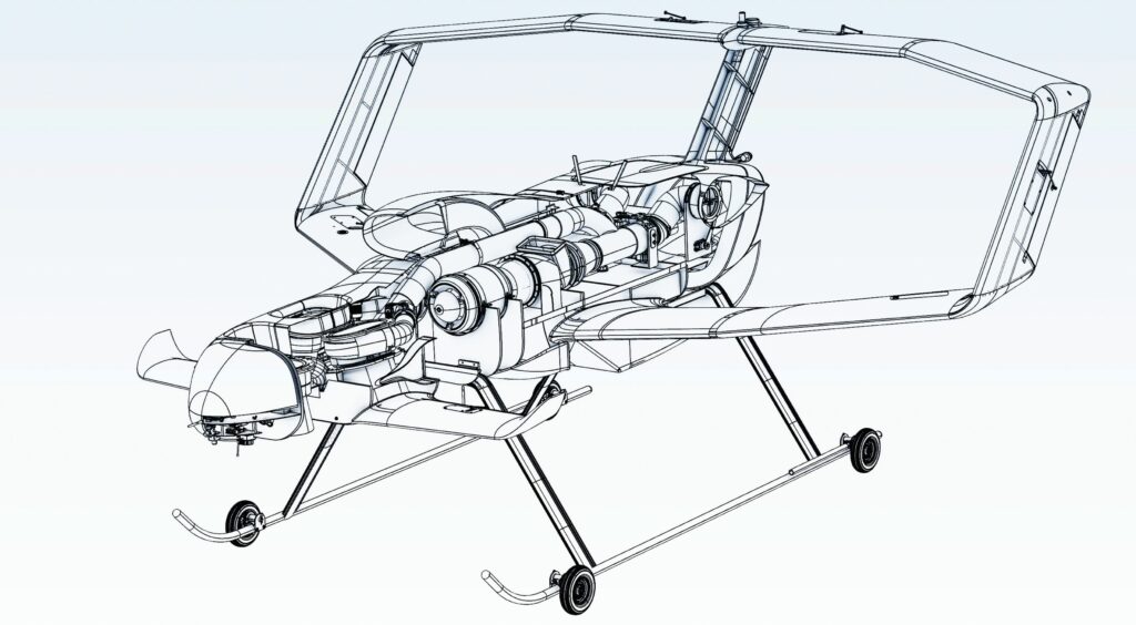
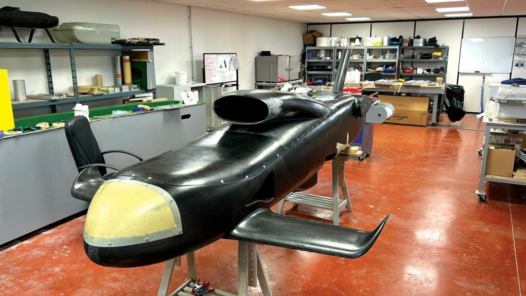
That and subsequent development work has fed heavily into Jetoptera’s first production iteration of its FPS technology, the FTC-250 powertrain, which down the line is also slated to power the company’s first production UAV, the J-500 (a 227 kg, fixed-box-wing plus canard, VTOL-transitioning craft, capable of 50 kg payload capacity and up to 200 knots true airspeed).
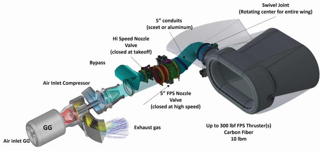
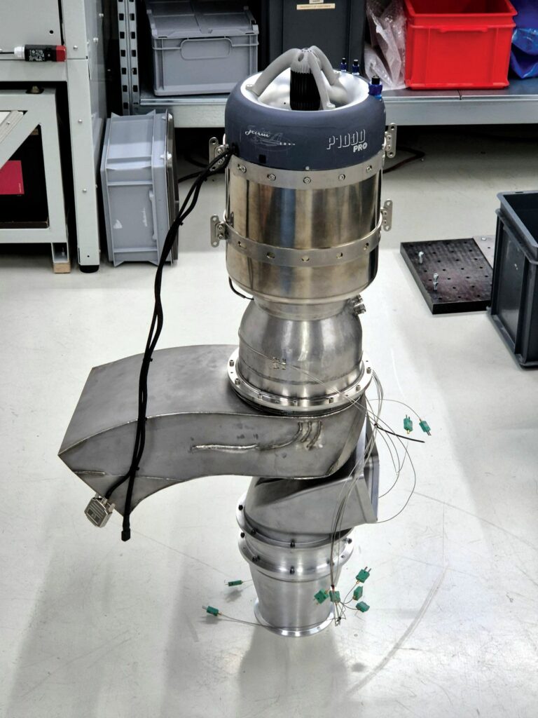
The FTC-250 powered FPS produces up to 500 lbf (226 kgf) of thrust, while weighing 115 lb (52 kg) or more, depending on exact configuration. Physical dimensions are variable depending on configurability, though as standard, a 10 in (25.4 cm) wide ‘free turbine compressor’ (hence, FTC) forms the middle, core operating stage in the powertrain. That is preceded by a gas generator (GG), as the prime power source, and followed by a series of conduits and valves, which are followed in turn by an arrangement of Coandă thrusters – with each of these stages to be explored below in an orderly fashion.
It additionally has a maximum specific fuel consumption (SFC) of 0.7 lb/lbf/h (0.7 kg/kgf/hr), a maximum operating altitude of 5000 m (16,400 ft), and a mean TBO of 200 hours. Technically, the frontal GG lasts for 50 hours on average, but can be modularly swapped out as needed with little labour, and even replaced with a different prime mover (hence, the aforementioned adaptability).
In addition to its modularity, fuel efficiency and agreeable power-to-weight ratio, the FTC-250 and other FPS embodiments by Jetoptera benefit from very quiet operation owing to the use of ejector-style Coandă thrusters instead of propellers, as well as from fairly simple in-built VTOL-transitioning attributable to the way that rotational actuators can be integrated between said thrusters and their conduits. The thrusters can be rotated and angled in a 100° range, covering vertical and horizontal flight, with power to each thruster metered via the aforementioned valves, thereby adjusting the output thrust as needed for each stage of transitioning or flight.
And because no propeller or rotor blades exist to enforce a specific, rounded form factor, the thrusters can be designed very flexibly, even conformal to aircrafts’ wings, tailplanes or fuselages (Jetoptera having successfully tested these in wind tunnels and in flight), capturing degrees of efficiency previously realised by few aircraft other than gliders, but potentially bringing its efficiency and VTOL benefits to high-speed aircraft capable of Mach 0.8. Hence, a wide variety of crewed and uncrewed aircraft applications, particularly near populated areas, might benefit from the efficient and relatively silent FPS methodology.
Before we explore each section of this unique powertrain and technology, a brief history and education in the system’s fundamental principles bears covering.
Fluidic propulsion
As Evulet tells us, fluidic propulsion functions analogously to a turbofan with a large bypass ratio, but instead of driving a bladed fan to move bypass air plus core air into a combustion chamber as the end-goal, that driven bypass portion of the air stream is used to fluidically drag or ‘entrain’ much larger amounts of air, similarly to how ejectors work.
For those unfamiliar with ejectors, these are a form of vacuum pump, in which a jet stream of liquid or gaseous fluid called primary or motive fluid moves with high velocity through a shrouded nozzle, its pressure becoming low owing to Bernoulli’s principle, and that low pressure then generates a vacuum via the Venturi effect. That vacuum draws in additional ambient fluid called secondary or entrained fluid, which mixes with the primary fluid via the nozzle’s narrowing diameter and diffusing section. The resulting mixture henceforth gathers enough velocity and mass flow to eject with increased thrust, typically from an expanded end-section of the ejector, so that the fluid pressure can smoothly increase to the ambient pressure.
Historical attempts at ejector-based thrusters, popular between the 1950s and 1990s (and laboriously studied in Jetoptera’s initial literature reviews), would largely entrain external air at a 2:1 ratio at best – their embodiments using a round shroud, around a central high-velocity jet unit, similar to modern off-the-shelf steam ejectors.
“But a Coandă ejector is somewhat inside-out, functioning via the Coandă effect in which the working fluid drags in secondary fluid based on how well the primary fluid ‘sticks’ to the curved walls of the ejector body,” Evulet explains.
“Their entrainment ratios – the equivalent of turbofans’ bypass ratios – are tremendously larger than conventional ejectors, maybe 20:1 if the application calls for it, meaning the prime thrust source’s original thrust is augmented to a final output thrust of 2.5–3 times over.”
It has taken Jetoptera years of exhaustive research to get their Coandă ejector right, including some minute information not included in their hundreds of patents or in this feature. That research included optimising the ejector curvature, determining the ideal stages of thrust generation, and identifying the optimal pressure ratio for achieving that 2.5–3X thrust augmentation over and above the frontal GG’s thrust.
“Too much compression and you get diminishing returns; we need a certain pressure ratio across our Coandă ejectors’ primary nozzles to get a fast expansion of our primary jets, which are adjacent to the walls, which in turn are designed to maximise entrainment of air, perhaps a 10:1 ratio as standard, and to do that with a turbofan it’d need to be enormous – a Rolls-Royce UltraFan or a GE9X – you can’t do air taxis or heavy-lift drones with that,” Evulet explains.
“We do get some minor losses in the conduits, but overall, we have more than enough thrust at quasi-static conditions for hover or VTOL from an engine sized for cruise.
“Compare that with the Harrier Jump Jet, which did no thrust augmentation; it had to redirect gases from an incredibly oversized and heavy engine to achieve VTOL and hover. The benefits of fuel energy density over today’s battery energy density would get mooted as a result, but with our system, we only need a small engine.”
Moreover, historical attempts at ejector thrusters – as covered by NASA and other research groups in papers available online – suffered from an absence of adequate CFD tools. Consequently, they were largely artisanal, hand-built systems, constructed with COTS turbofans and mixed-flow exhausts (instead of a separate bypass, as per the FTC-250, as we will see), driving 900 F (482 C) hot air into their ejectors.
“But instead of doing that, or instead of doing the turbojet way of ejecting a small trickle of hot gas at 1500 mph [2414 kph], we’re moving massive amounts of air at maybe 300–500 mph, which works because thrust is simple mass flow rate multiplied by velocity,” Evulet says.
“We’ve massive amounts of CFD and test data proving that it’s more efficient to drive compressed, cold air into your ejectors, which is why we place the FTC after our gas generator and before our ejector-thruster.
“That hot gas in the old attempts suffered really ‘sticky’ flow along the ejector walls, and the walls had to be heavy titanium to withstand the heat and pressure; huge losses ensued. But they had no CFD to predict the results of different airflows, no additive manufacturing [AM] to control the design, and no decent funding to pursue thorough development. We have all three, so we’ve optimised our system with better geometries, fluid flow and compressed, cold air, meaning total-to-total pressure estimated losses of just below 2%.”
Evulet notes that he met and spoke with NASA’s Michael Dudley about this topic eight years ago. Dudley was involved in NASA Ames Research Center’s wind tunnel investigations (and ultimately, rejection) of ejector propulsion in the 1980s, and in 2016 published a paper validating Evulet’s insights about the technology.
That paper (https://ntrs.nasa.gov/citations/20160011546) recommended revisiting ejector technology, stating that past analyses of its value were unscientific, imprecise and unfair, and that the advent of high computational power, major CFD advancements and metal AM could power potentially massive gains in its thrust efficiency.
Jetoptera adds that its CFD tools included Altair’s Flow Simulator software for 1D flow network analysis, primarily on the FPS’s air supply system, and Siemens’ STAR-CCM+ for detailed 3D analysis. New York-based Gas Turbine Combustor Development, LLC also executed the lion’s share of the third-party simulation work, and the advanced digital tools for predicting Coandă ejector performance are developed, owned and protected by Jetoptera.
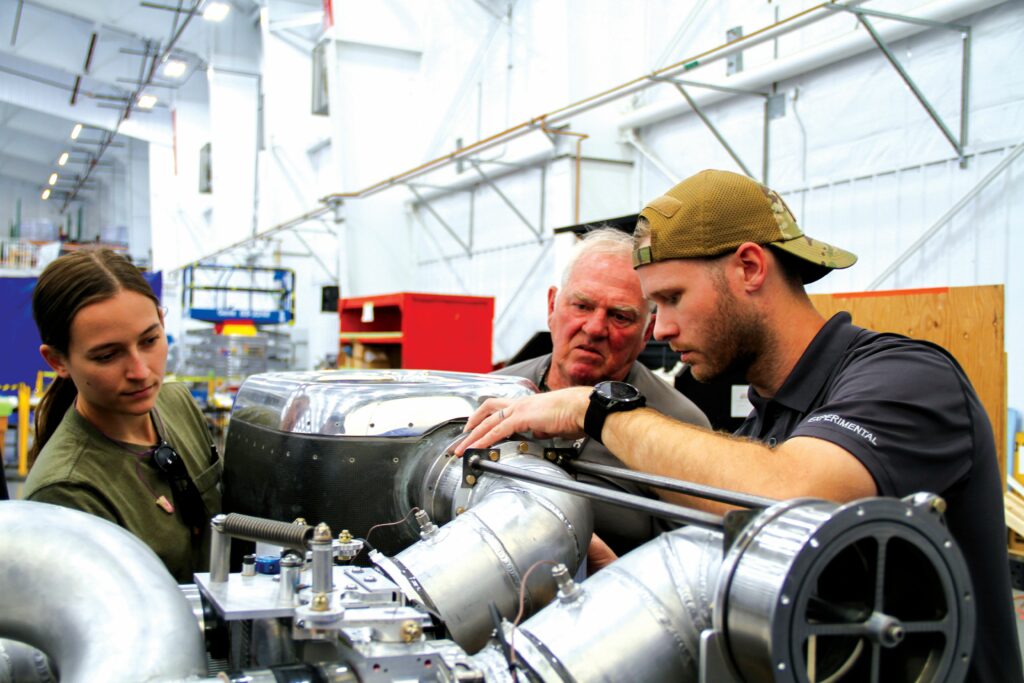
The FTC-250
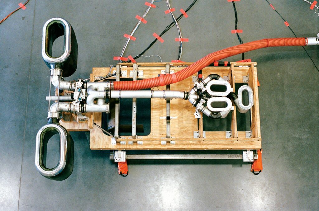
An entire FPS powertrain may encompass both horizontally disposed rear thrusters, rotatable via a servo joint and vertically oriented front thrusters fixed in position, and indeed the J-500 UAV’s FPS layout does so.
Potential variations aside, the FTC-250 solution begins as standard with a GG based on a COTS turbojet that Jetoptera modifies by replacing its thrust nozzle with an inlet for the FTC. Thus, the GG’s hot, compressed gases then drive a free turbine (so-called because it runs mechanically uncoupled from the forward GG microturbine), which in turn drives a two-stage axial compressor (or turbocompressor).
Although great thrust augmentation and, hence, efficiency are gained via the patented Coandă effect thruster, Jetoptera is also considering the integration of ceramic matrix composite (CMC) components in the hot section of its powertrains to overcome the limitations of fuel efficiency in microturbines. This will enable FPS powertrains to reduce their weight, minimise their cooling requirements and increase their firing temperatures, which will in turn reduce their fuel inputs, thereby maintaining thrust while reducing SFC.
“You would also improve microturbine fuel efficiency by increasing its core pressure ratio – which is doable but requires optimisation work by the supplier – and you can add a recuperator for heat recycling, as Turbotech [see Issue 31], UAV Turbines [Issue 11] and Turbine Aeronautics do successfully,” Evulet says.
“But recuperators generally add weight, especially when you start to go over 100 kW, as my colleagues and I at GE discovered at length when researching recuperators for power generation.”
Given Jetoptera’s wish to stay agnostic to its primary compressed air source, and the varying sizes of powertrains it plans to offer for crewed and uncrewed systems, investing r&d into recuperators as a ‘one-size-does-not-fit-all’ solution was seen as suboptimal. The company anticipates higher pressure ratios and raised firing temperatures to become more commonplace for fuel saving as ceramic parts for small turbines grow in availability.
Past the compressor’s outlet, the highly compressed air passes into a first manifold, featuring one main channel leading to control valves for flow and thrust modulation, the thruster with its rotatable joint and a bypass channel for sharing compressed air with the other thrusters, for enabling balanced thrust distribution across the UAV.
The control system opens and closes the valves to determine the flow rate and pressure of the air that passes through to the downstream thrusters, vectoring thrust to suit whether the system is flying in VTOL, cruise or high speed (enabling the GG to keep running at its optimal rpm).
These and the thruster’s swivel joint are governed by electromechanical servos from Volz, chosen for their hardiness and longevity, as well as their quick throttle response, which enables transition between vertical and horizontal flight (and vice versa) within six seconds, with even that short latency coming more from the J-500’s 227 kg MTOW than any limitation on the Volz servos.
Between the nozzles and joint is a manifold of either thin aluminium or SCEET (aviation-grade, silicone-lined tubing), with a silicone-based joint connecting the first and second manifolds, which also provides sealing and baffling to compensate for thermally expanding components.
“The temperature of the air passing through that manifold is less than 150 C, and with a 2:1 pressure ratio; it’s very benign. That’s a big reason we save so much weight because we don’t need oppressively heavy metals to contain the pressure or heat like they attempted in the past when they were using the mixed bypass air and hot core exhaust gas to feed the ejectors,” Evulet says.
Overall, a single FTC-250-powered FPS, as standard, technically consists of one sequence of a GG, FTC, manifolds, valves, swivel joint and thrusters, as described above. The complete J-500 prototype powertrain is a set of two FTC-250s; hence, two rear thrusters with three additional, fixed, vertically disposed forward thrusters, all interconnected via bypass manifolds of the type previously mentioned, to ensure balanced thrust during VTOL. Each forward thruster has a single valve (also Volz-actuated) to shut them off during horizontal flight, with the rear thrusters (combined with flaps, rudders, tilt-wings or so forth) angling as needed for attitude control.
Gas generator
Jetoptera preferentially uses microturbines from Jetcat, with a modified P1000 on the FTC-250 and a derivative of the German company’s P550 used for initial proof-of-concept flights.
“Jetcat is one of the largest manufacturers of small turbojets for both military and civilian applications; I knew about them back in my GE days and was very impressed with their quality,” Evulet says.
“I spent some time with them, visiting their facilities and convincing them to make our modified P550 system; today, I suspect they might be the best in the world at systems of their size, power and cost. Like many other turbine experts, they were in some disbelief that our system would really work, until we took our test rig to them, measured our thrust and actually stuck their hand through the test thruster to see that it really is just high-mass, low-velocity, low-temperature, entrained air driven thrust generation.”
For the J-500, the standard P1000 – as with virtually all turbojets – integrates a convergent nozzle at its outlet for concentrating its hot, pressurised exhaust into a concentrated
1500 mph stream of thrust-generating air. As indicated, Jetoptera’s requested modification of the P1000 consisted solely of removing this nozzle, resulting in the present-day GG.
“Replacing that nozzle with our FTC hot gas transition piece gets us a better, more efficient flow for driving our free turbine and thus our two-stage compressor; there’s maybe a little further optimisation in the future, requiring a bit more modification to the GG, but this way works great for the initial introduction on the J-500,” Evulet says.
“Future GGs on future products probably won’t be the P1000 exactly because we’re working on something better with higher pressure ratios and potentially ceramic hot gas path components that can shave off a quarter of the current fuel burn, like we talked about. It would also improve significantly on the TBO to over 200 hours.”
As mentioned, the GG may be replaced with any other kind of compressed air source, including electric compressors (one 300 V, 200 A compressor from BorgWarner having been trialled successfully), or turbines optimised for fuels compliant with environmental regulations, such as hydrogen, biofuels, or SAFs.
And while the FTC-250’s GG runs on jet fuels as standard, it can also burn diesel, provided some oil is mixed in. Jetoptera notes here that the small turbojet’s bearings and their lubrication requirements are the main reason for its 50 hour TBO; hence, significant research is going into longer-lasting bearings to extend the FTC-250’s maintenance interval.
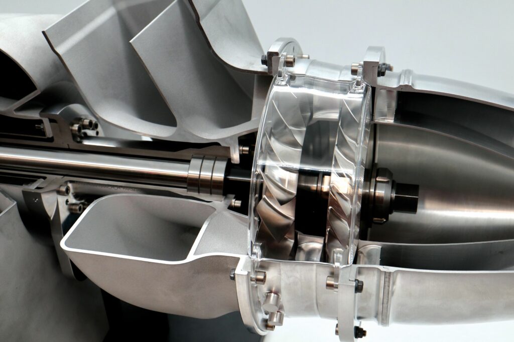
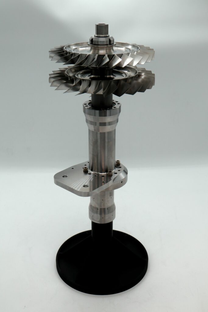
Turbine & turbocompressor
Design of the FPS air supply system, running from the GG into the free turbine, and then from the compressor to the thruster, utilised both 3D and 1D analyses. As Jetoptera describes to us, the 3D CFD analysis was used to help define the 1D flow network element layout, and optimise the 1D modelling results. The 1D modelling was then used to rapidly assess changes to the system configuration and sizing to provide the required flow and total pressure at the inlet to each thruster.

The proprietary FTC system, encompassing the exact architectures and geometries of the free turbine, axial compressor and shaft between them, was designed with crucial support from Parametric Solutions of Jupiter, Florida, with that company consulting on and outputting designs to Jetoptera using the latter’s continuous input, requirements and feedback (“In record time,” as Evulet tells us).
The system was then built by Van Der Lee Turbo Systems in Zaandam, Netherlands, Jetoptera citing the Dutch company’s pedigree in motorsport (Formula One included) and aerospace turbochargers as having been key to its quality and high capability, as was its network of subcontractors.
The GG’s hot (but annularly distributed) exhaust gas flows and expands over the free turbine, transforming the gas’ energy into torque, which drives the turbocompressor much as a helicopter’s turbine drives a gearbox and rotors, or as a turboprop’s turbine drives a single reduction gear and propeller.
The transition piece from the GG to the turbine, containing the turbine inlet guide vanes (IGVs) was manufactured using AM. The turbine wheel was cast and machined with abradable shrouds used to enhance its performance. Great attention was paid to its design using 3D aero tools and enhanced features for the aerofoils of the vanes and blades.
A two-shaft system connects the turbine and compressor. However, rather than nesting the two shafts together, as in a turbofan, they are connected in series one after the other, with the second using pre-greased bearings with no active oiling required. The system’s cooling and lubrication (and those of its bearings) are aided, however, using a minute trickle of the turbine’s air outflow.
“The FTC uses four bearings in two locations and they last a very long time – hundreds and hundreds of operating hours – so long as we keep that grease within a particular temperature range,” Evulet adds.
The turbine and compressor move at a maximum speed of 38,000 rpm during normal operations (thrust being metered not by their speed but by the nozzles downstream), which is notably lower than the P1000’s 61,500 rpm.
The reason for designing the compressor as a two-stage axial machine (or a single compressor with two axial stages) rather than a centrifugal compressor is that the latter approach typically compresses a trickle of air at very high pressure ratios. At this stage of the powertrain, Jetoptera has no need for pressure ratios higher than 2.5. Changing that figure would mean re-optimising for flow quantities and pressure differentials along the subsequent manifolds, in order to get the precise primary airflow needed for driving the ejectors at the thruster end of the powertrain.
Jetoptera had previously planned to additively print the designs of the turbine and compressor as they currently stand, and indeed extensive AM has been key to development so far. However, as of writing, just three sections are printed: the transition piece that enshrouds and seals the inlet from the GG to the turbine – including the IGV, the turbine exhaust manifold (owing to some small and geometrically complex baffles inside) and the air inlet section to the turbocompressor.
“We use powders of Hastelloy [a nickel-molybdenum-chromium alloy from Haynes International] to print the transition piece; and that last inlet part might sound simple, but it’s directing in the turbine’s output gas from one, concentrated side and then distributing it equally all over the periphery of the turbocompressor turbine wheel. So, geometrically, it’s complicated enough that it makes more sense to print it than CNC machine it,” Evulet says.
“The rest are machined: turbine, shafts, stators, rotors and even the outlet from the compressor. Mainly we use aluminium, including in the compressor, but we do use titanium alloys for both the compressor rotors, as well as some very typical, high-temperature stainless steel alloys on the turbine to endure the heat.”
The aforementioned exhaust section expels much of the gas’ remaining heat from the turbine before the air can enter the compressor, aiding greatly against hot gas re-ingestion into the air inlet. Its noise remains minimal because the gas exits at roughly 100–200 mph (161–322 kph) thanks to the design of the internal baffles.

“Of course, you need to size the exhaust so that it doesn’t slow the aircraft, but it’s not doing too much work as most of the gas’ kinetic and thermal energy will have been extracted directly by the turbine, and like elsewhere in industry, we’ll often use that exhaust stream to create another ejector which pulls stagnant air out of the aircraft. So, it’s just as important a section of the FTC to keep optimised as the turbine and the compressor,” Evulet says.
Fine response
Each of the five thrusters has a single control valve, with each of the two rear powertrain sections also integrating an additional high-speed valve (HSV), these coming into play (briefly but crucially) during transitions between vertical and horizontal flight. Each of these seven valves (or nozzles) is a butterfly valve, operating via a cam-actuated assembly to achieve ideally linear and highly controlled and predictable performance, and measuring 5 in (12.7 cm) in diameter for the rear thrusters and 3 in (7.62 cm) in diameter for the forward thrusters.
Engineering for the network of thrusters and valves is led by Gene Katz, consultant to Jetoptera and veteran former engineer for General Dynamics and Cloud Cap Technologies.
Katz first observes some critical properties of the thruster layout for us. “When looking at the forward thruster configuration for the J-500, you can see the two radially disposed ones are also canted 10° off the vertical axis. That allows any UAV integrating this powertrain very fine yaw control, basically using differential thrust vectored on those two.”
The remaining, forwardmost thruster is distinctly vertical and uncanted, thereby providing pitch control owing to its placement giving an ideal lever ratio to the CoG. Together with the rear thrusters orienting downward, the UAV can precisely target attitude adjustments while in VTOL or hover, despite the very delicate and nontrivial nature of maintaining balance and control in these states of flight.
“As you know, we actuate those thrusters’ valves using Volz servos, which are very well known and established in aviation, including in industrial drones. And their selection is supported by the size and ruggedness of their packaging for aircraft applications,” Katz continues. “They also provide a large range of torque and size configurations, and – maybe most importantly – their servos come with a digital command interface with telemetry feedback. So, we’re not driving them with traditional, analogue, PWM signals – driving them with a single digital bus is optimal for reduced cabling and EMI shielding needs.
“Plus, with the telemetry feedback, we get positive information for precise command and control and, overall, their control loop response time is excellent: the quality of each valve’s flow control is proportional to the speed of its servo. We don’t get rotary or prop inertia problems, so we have test data proving we can do 50 ms signal responses and control changes in VTOL, compared with the 500–1000 ms VTOL flight responses of conventional electric quadrotors, making our approach to distributed lift way better for handling turbulence.”
Close control is also critical for the HSVs. While the collective pressure across the network of channels connecting the two GGs and five thrusters is theoretically enough to achieve supersonic jets at peak power output via the entrainment at the rear thrusters, it can also cause the two turbocompressors to stall if excessive downstream air pressure builds up.
To avoid this, the HSVs will open at a key moment during VTOL transitions, when the forward thrusters’ valves shut them off from the air network, so that the excess air no longer leaving via those pitch and yaw thrusters can instead escape via the high-speed nozzles out the back of the aircraft, in addition to feeding the rear thrusters as they pitch from downwards to rearwards.
Thus, they provide some minimal forward thrust (with no entrainment, hence just a fraction of the rear thrusters’ power) while the rear thrusters adjust attitude, and some relief as a wastegate for the turbocompressors, much as the original P1000s each feature a bypass valve to supply air for secondary uses, such as pressurising fuel tanks.
The swivel valve sitting just prior to each rear thruster incorporates a ring bearing, enabling the thruster’s side to rotate without obscuring the air passage. Each swivel valve is actuated via one of Volz’s redundant duplex servos, which integrate dual powertrains of inverters, electric motors and gearboxes, ensuring continued (if slightly slowed) VTOL transitioning in the event of one servo powertrain failing.
“And again, the ruggedness of Volz’s servo packaging is really critical for the degrees of power and mass flow we’re handling, and the kinds of turbulence we want to be able to deal with – they’re certainly not cheap, that’s for sure,” Katz laughs. “But with servos, you get what you pay for. There’re other brands out there but Volz is undoubtedly the best for our application right now.”
Control
With the Jetcat turbojets persistently running at their optimal speed, and thrust metering achieved simply via the valve servos, it’s not necessary to have complex engine management software, ECU hardware or FADEC for governing the FTC-250 or broader UAV powertrains from Jetoptera.

Instead, Katz notes to us: “As exotic as it looks from above, the control functions of our powertrain are actually highly analogous to the flight controllers you get for multi-rotor-type distributed lift platforms. From a software perspective, the servo-driven valving looks exactly like the motor controller network on a quadcopter; we talk to our servos’ motor controllers with a flight controller just as any UAV autopilot talks to its electric rotors’ motor controllers, we’re just targeting mass flow rather than rpm.”
Any errors against commands are sufficiently detected using any open-loop IMU already present on the UAV, adjusting for attitude based on that inertial feedback. Some extra tuning is required to ensure the FPS’s balancing for VTOL and hover, given Jetoptera’s greater mass and tighter response loops than electric multi-rotors, as well as the moderately different aerodynamics of the J-500 or other fixed-wing UAVs integrating powertrains based on FTC-250s.
“That includes completely different configurations, like FTC-250s maybe driving four or six rear thrusters; since we understand exactly how to size our piping, how to place our valves and so on, we’re very flexible in how we can reshape the whole powertrain without losing a grain of controllability or balance,” Evulet notes.
“You can see that on our website, with our high-speed VTOL model using much smaller thrusters, distributed over a wing, with a manifold running inside the wing, making for an upper-surface blown wing configuration to generate extra lift at higher velocities. When retracted into the wing, the compressed air bypasses the thrusters and is expanded via high-speed nozzles, making the aircraft both aerodynamically clean and more than enough thrust to go to speeds thrice as high as any rotary wing aircraft, including tilt rotors.”
Future improvements may include programming PID loops around each valve, which would further enhance their performance, while adding a modicum of complexity into the software. Other advancements in flight control software may also benefit Jetoptera’s powertrain control.
“What’s especially interesting is that some flight controller packages now bring varying measures of certification with them. So, our selection of controllers really comes down to whichever flavour the end-integrator likes best for their system and mission,” Katz adds.
“As for us, we’re custom-developing our own, so that we can offer what we feel is an optimised control package. But that doesn’t preclude a customer using someone else’s software or developing their own control functions for a powertrain we’ve provided for them. Controlling an FPS doesn’t come down to complicated science so much as solid programming work.”
Thrusters
As pressurised air passes through the swivel valve, it first enters an annular chamber around the front of the thruster, distributing it throughout an internal set of primary nozzles. The volumes and geometries of these nozzles are proprietary – having been optimised through exhaustive r&d – and critical to how the air goes from its manifold pressure ratio to ambient in a controlled manner. These can also be designed specifically for the application for which the customer needs the propulsion.
“That creates a low-pressure area in the front of the thruster, so that massive amounts of ambient air rush in to fill that area, getting sucked in and dragged through the thruster,” Evulet says.
“Those jets of entrained inrush air then stick to the walls inside the thruster, bending to follow their curvature and so achieving the Coandă effect we previously talked about. Those dynamic jets accelerate, and a very thorough [and well-engineered] mixing follows, where the wall jet of very high-velocity air grows to fill up to the centre of the thruster, while admitting and entraining more air still from the surroundings.”
The end result is a near-uniform velocity profile of air exiting the thruster because the mixing process has taken place very quickly, and the high-energy wall jet has diffused into the core area in the middle of the thruster, giving an almost perfectly unidirectional output thrust with close to constant mass airflow (with some minimal peaks occurring, depending on each thruster’s design parameters).
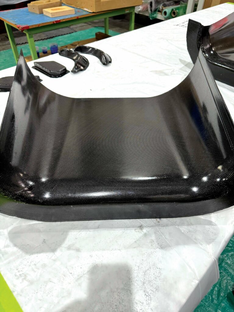
The FTC-250’s thrusters have been manufactured and trialled using many different materials, including various metals and plastics, as well as different machining and printing methods. In some tests running particularly hot gases through the thrusters, cast titanium and CMCs were used, with Jetoptera’s original flights having been made possible with CMC thruster bodies from Walter E.C. Pritzkow Spezialkeramik. Jetoptera also tells us that this Stuttgart-based company has a unique formula for the oxide–oxide CMC that enabled production of the extremely lightweight, easily swivelled and high-temperature thrusters.
“We even made silicone thrusters to try compressing and hiding them in a wing during Mach 0.8 flight, and seeing how well they inflated after being deployed for vertical take-off and landing,” Evulet adds.
In the J-500, carbon composite rear thrusters are presently used, based on test results from supplier AeroTEC indicating that such material gives the best performance-to-weight ratio. In future, however, Jetoptera anticipates moving to hydroformed and welded aluminium thrusters because these will give even better reliability and far reduced costs, without incurring significant weight increase. The frontal aluminium thrusters meanwhile come partially from Keselowski Advanced Manufacturing (KAM) – now a subsidiary of ADDMAN – and which provided consistent support and quality in its additively printed parts for Jetoptera. JJR Fabrication have provided additional components for these thrusters.
AeroTEC also provided invaluable support in this and other projects with Jetoptera, through key in-house and certification-compliant development capabilities, as well as providing its Flight Test Center in Moses Lake, WA (USA) for all of Jetoptera’s systems testing to date.
Design of the thrusters relied heavily on 3D CFD, first through setting CFD model requirements to match thrust measurements from wind tunnel tests of the original thruster configurations.
“These are challenging analyses, modelling transonic flow conditions with large-scale air entrainment from the upstream environment; both steady-state and detached eddy simulation transient analyses were evaluated and used in the design process,” Evulet says.
“After validating the modelling approach, new thruster configurations were designed, with excellent agreement between predicted and measured thrust. This validated process allows Jetoptera to develop new thruster configurations for a wide variety of new applications.”
3D CFD analyses of the thrusters on the airframe were also performed to assess thruster performance at various operating conditions, including cruise conditions at sea level and design altitudes, and during VTOL operation. Such analyses provided key feedback on thruster design, airframe design and layout, and location and orientation of hot exhaust flow from the gas turbine.
And, as mentioned, the thrusters’ bladeless operation yields atonal thrust, meaning significant noise reduction – up to 40 dB lower than an equivalent power bladed system, as Jetoptera states, measured at the same distance. Low-frequency noise sources like propellers cause far-travelling noise through the atmosphere with little or no attenuation, but the almost frequency-less thrust from the FPS more closely resembles the acoustic characteristics of white noise.
“We hired Dr Robert Dougherty – formerly of Boeing but now of OptiNav – who received the prestigious AIAA aeroacoustics prize in 2019 for his contributions to the art of measuring noise, to analyse our thruster noise, and he said: ‘Your device is going to sound more like the wind’,” Evulet muses.
“That’s vital to air mobility because current air taxis built with props and rotors just won’t be allowed to operate around the clock in cities like their makers claim they will; they’re too noisy for human health regulations. It’s not the motor that creates noise, it’s the blades, regardless of whether they’re driven electrically or by shaft horsepower.”
Conclusion
Along with continuing remaining r&d on its powertrains, its J-500 UAV and its J-2000 air taxi, Jetoptera is still expanding its ranks to better tackle its projects across commercial and defence applications. With its technology highly matured and capable of flexible modularity without sacrificing optimisation, one can expect to see Jetoptera’s technology across skies from the Americas to Asia before long.
Key specifications
FTC-250
Ejector-based fluidic
propulsion system
Turbojet thrust
Minimum bypass ratio (turbofan): 1.5
Minimum pressure ratio: 2.1
Minimum weight (turbofan): 50 lb (23 kg)
Minimum weight (FPS): 65 lb (29 kg)
Minimum total weight: 115 lb (52 kg)
Maximum thrust: 500 lbf (226 kgf)
Maximum SFC: 0.7 lb/lbf/hr (0.7 kg/kgf/hr)
Maximum FTC power: 250 kW
Maximum altitude: 5000 m (16,400 ft)
TBO (gas generator): 50 hrs
TBO (FTC-250): 200 hrs
Some key suppliers
CAD support and manufacturing drawings: Alternative Design Solutions, Inc.
3D CFD analysis: Siemens
1D flow network analysis: Altair
Simulations: Gas Turbine Combustor Development, LLC
Turbocompressor design support: Parametric Solutions
Thruster components: JJR Fabrication
Composite manufacturing and Testing/Certification: AeroTEC
Additive manufacturing: Stratasys
Additive manufacturing: ADDMAN
Metal additive manufacturing: EOS GmbH
Ceramic matrix composites: Walter E.C. Pritzkow Spezialkeramik
Turbomachinery Manufacturing: VAN DER LEE Turbo Systems
Gas turbines: Jetcat
Servos: Volz
UPCOMING EVENTS


