


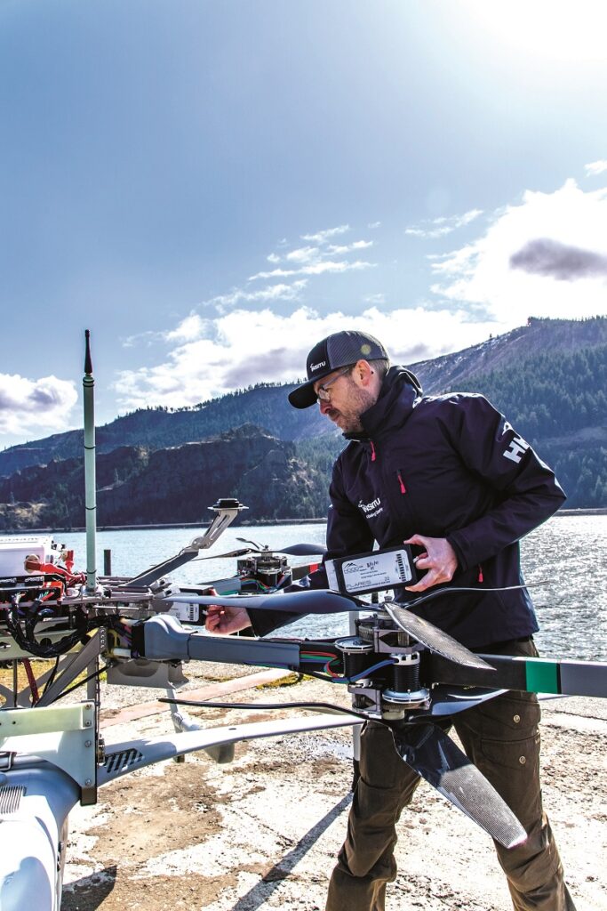
Insitu’s ScanEagle & Integrator
Rory Jackson speaks to the company behind this iconic, fixed-wing UAV and its sibling – progenitors of much of the modern industry that now exists around them
Eagle-eyed veterans
Since the dawn of the century, countless programmes for high-end, long-endurance UAVs have come and gone, with varying degrees of success and contribution to autonomy, aerodynamics and power for uncrewed systems. Few have managed to stay the course quite like Insitu’s ScanEagle has.
Since its inaugural flight in 2002, this iconic, fixed-wing aircraft has flown across Arctic, desert and ocean environments worldwide to now serve customers in 35 countries. It performed the first FAA-approved, commercial, beyond-visual-line-of-sight (BVLOS) flight in US national airspace in 2013.
Located in Bingen, Washington, Insitu was founded in 1994 by engineers with a collective ambition to develop robotic aircraft for remote, in-place (or in-situ) atmospheric monitoring, before pivoting into monitoring for the tuna fishing industry with its SeaScan aircraft around the end of the 20th century.
With the advent of the US War on Terror, Insitu saw the potential for uncrewed aircraft in military intelligence, surveillance and reconnaissance (ISR), so SeaScan was redesigned and rebranded as the ScanEagle, going on to be used widely as an aerial, full-motion video tool for numerous defence organisations.
Since then, a vast ecosystem of tech firms has spawned across the US West Coast to support Insitu and the many aerospace manufacturers (uncrewed or otherwise) that its alumni have spun out. The company has also birthed other aircraft from its amassed pool of r&d, the most successful being the Integrator UAS, first announced in 2007 as a larger, more modular cousin to the ScanEagle, and designed around intermodal transport and expeditionary assembly.
Such is the size and symbiosis of Insitu relative to the wider UAS space that the development history of its two aircraft is, in many ways, a microcosm of the industry’s story as a whole, with their capabilities being adapted to meet changing military demands as such users realised what 15-25 kg UAVs were technologically capable of.
As Michael Hartley, product manager for the Insitu ScanEagle, says: “In much of its early military usage, ScanEagle really just flew full-motion video payloads, but then demand for additional payload capabilities started coming in, specialised for varying mission sets.
“In its second decade, there was a significant design effort throughout Insitu to modernise ScanEagle from its old, serial-based, analogue architecture to a system of digital networks, high-end computers and modular adaptability, with the result that what customers are flying today is technologically very different to what flew in Iraq in 2005.”
The Integrator has built on the lessons gleaned from ScanEagle, initially to serve requests from the US Navy and Marine Corps in 2007. This morphed into the Small Tactical Unmanned Aerial System (STUAS) competition, which Insitu won in 2010 (under the product designation of RQ-21A Blackjack).
“Like ScanEagle, Integrator has predominantly been used as an ISR platform, but, technologically, it has evolved past that as market applications for its higher endurance and payload capacity have grown and diversified to include ISTAR [intelligence, surveillance, target acquisition and reconnaissance] and maritime domain awareness,” says Steven Todorov, Insitu’s senior product manager for the Integrator UAS.

As of writing, the Integrator has a maximum take-off weight (MTOW) of 74.8 kg, a wingspan of 4.9 m and a length of 2.5 m, with an 18 kg payload weight limit and 350 W of payload power capacity. Through its engine it can achieve airspeeds of 90 knots (46 m/s), altitudes of 19,500 ft (5944 m) and endurances of up to 24 hours (or 16 hours at maximum payload).
The ScanEagle, by contrast, has a 26.5 kg MTOW, a 3.1 m wingspan and a length of 1.71 m length. Maximum endurance is 18 hours, with a flight ceiling of 5950 m and an 80 knot top speed.
These differences mark the complementary nature of the two platforms. Integrator may be slightly larger and heavier, with advantages in endurance and payload capacity, but it nonetheless leverages vast portions of the technical know-how gained from ScanEagle’s development.
To Insitu, one of the most important shared technical properties between the ScanEagle and Integrator is their historic use of the same launch and recovery equipment (LRE). For most of the last 20 years, this has consisted of the company’s well-documented Mark 4 pneumatic launch catapult and SkyHook rope-capture assembly.
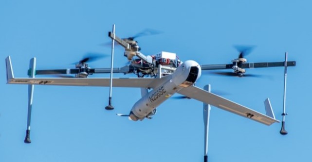
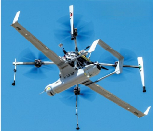
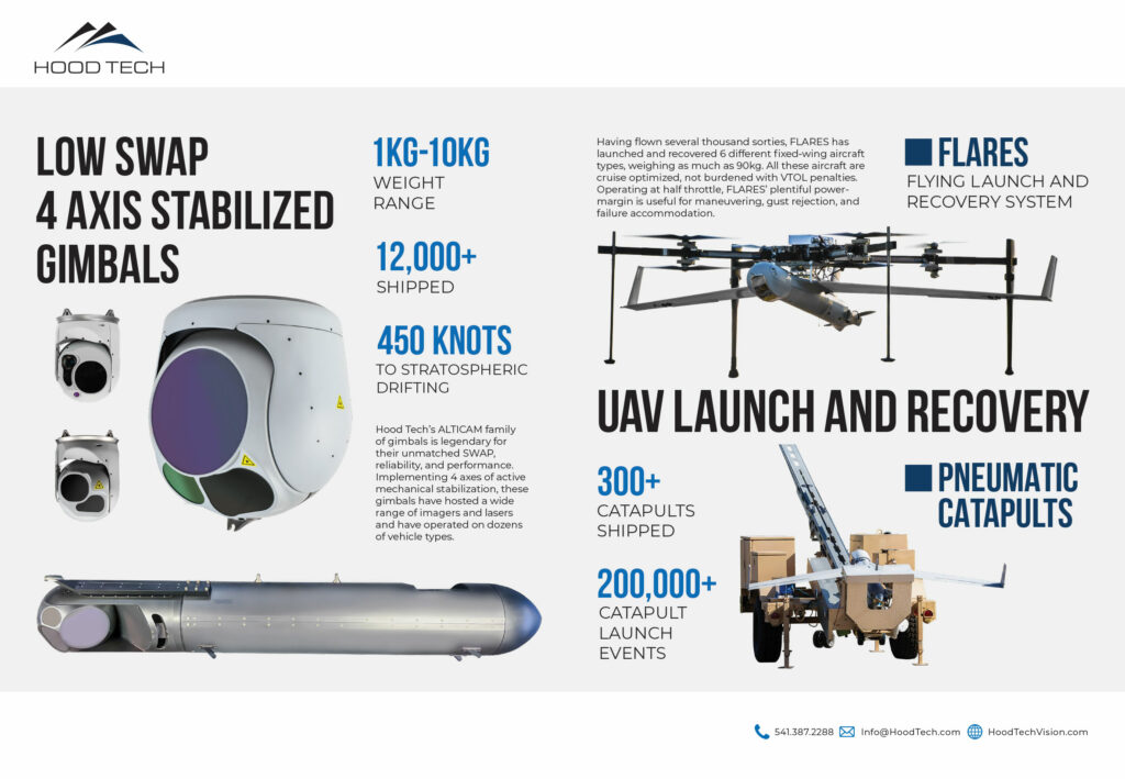
But, today, as vehicle take-off and landing (VTOL)-transitioning has taken the UAV world by storm as a must-have capability across all applications, Insitu has optimised and matured its Flying Launch and Recovery System (FLARES), developed by Hood Tech Mechanical, as a mission-ready solution for VTOL with either UAV.
Insitu in the age of VTOL
Paired with FLARES, the UAVs are now designated as the ScanEagle VTOL and Integrator VTOL. No modifications or upgrade packages are needed on either craft to form a seamless solution.
FLARES is essentially an automated multicopter in its own right, which in takeoff grips an Insitu fixed-wing UAV underneath by the latter’s wing roots. In recovery, it equips a rope to capture the fixed-wing UAV before lowering it to the ground, with the latter remaining very similar to SkyHook, both, for instance, using Differential Global Position System (DGPS) or other satellite positioning, as well as the same software logic to line up the capture rope with the wing of the UAV.
“Because SkyHook could be installed and operated on a variety of ship classes, its users could recover ScanEagle [and eventually Integrator] off of ships’ sides, without the hazardous across-deck approach that nets often needed,” Hartley says.
In time, some customers notified Insitu that they still had to conduct takeoff and landing with a flat, horizontal approach, which could not tolerate obstacles such as trees or buildings, and by the early 2010s the language of VTOL was promulgating audibly around the industry.
Justin Pearce, vice-president of programs, engineering and flight at Insitu, says: “Maintaining the success of ScanEagle and Integrator mandated a VTOL capability that wouldn’t compromise our endurance or payload performance by disrupting the weight, balance and aerodynamics with onboard lift rotors, tiltrotors, and all the extra electrical and electronic systems needed for those to run safely.
“Separating the VTOL component away from the fixed-wing UAVs into its own, packetised, independent LRE became the agreed way forward, so we started working with Hood Tech – started by former Insitu founder, Andy von Flotow – on FLARES.”
By 2015, FLARES had been prototyped, with the two West Coast companies juggling trade studies into available motors, ESCs, software integrations and other key engineering options. In 2019, serious interest in FLARES came from a long-time military customer for reducing its equipment footprint (compared with the catapult-and-SkyHook approach).
Successful trials followed, and as Insitu and Hood Tech had iterated FLARES into a stable configuration (referred to internally as FLARES 2) in both software and mechanical terms by then, initial customer training started soon after in 2020, with the first units fielded in 2021.
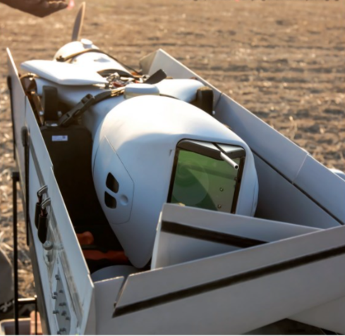
“That came with our Common Ground Control Station (CCGS), a productionised, reduced-footprint version of our previous ground control systems for ScanEagle, so customers received packouts that fitted in the back of a pickup truck – meaning ScanEagle and its peripherals were packaged into a very SWaP [size, weight and power] optimised UAS that could be launched and recovered pretty much anywhere, and operated from moving vehicles in tactical, mobile situations,” Hartley says.
Since 2021, Insitu has continued investing in and rapidly developing FLARES to scale it up for use with Integrator. Rather than simply picking bigger e-motors, ESCs and props, the company opted to start doubling up the drive components, enabling redundancy while still leveraging the vast bodies of legacy test data on the components being carried over into what is today known as FLARES 3.
“The larger, Integrator-version FLARES 3 has been in tests for 2.5 years now, with around 300 sorties tallied up on it,” Todorov says.
Although FLARES was originally designed as manually operated, today it is highly automated, with only a couple of button pushes required from the operator, and it has gradually overtaken the catapult in standard launch.
ScanEagle architecture
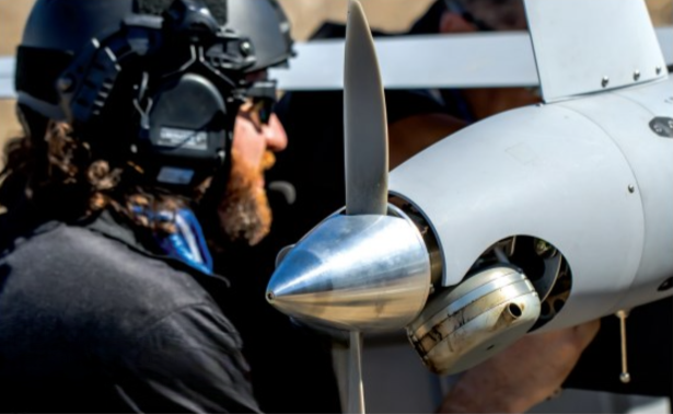
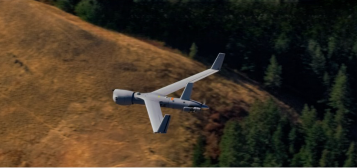
The ScanEagle airframe was designed from the outset with a cylindrical fuselage, with the shape having been deemed optimal for aerodynamic efficiency and endurance. Typically, the body consists of four sections: from front to back, these are a nose, a main fuselage, a fuel section and a propulsion section. Two wings and two winglets fasten at the sides to complete the airframe.
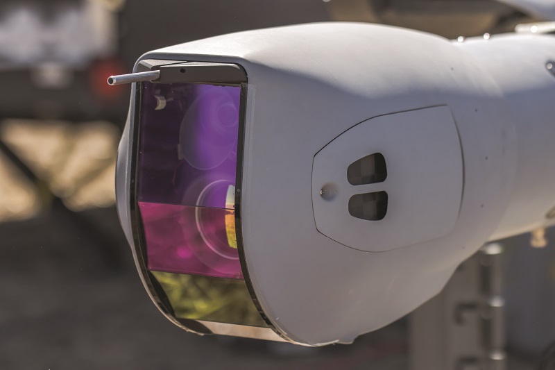
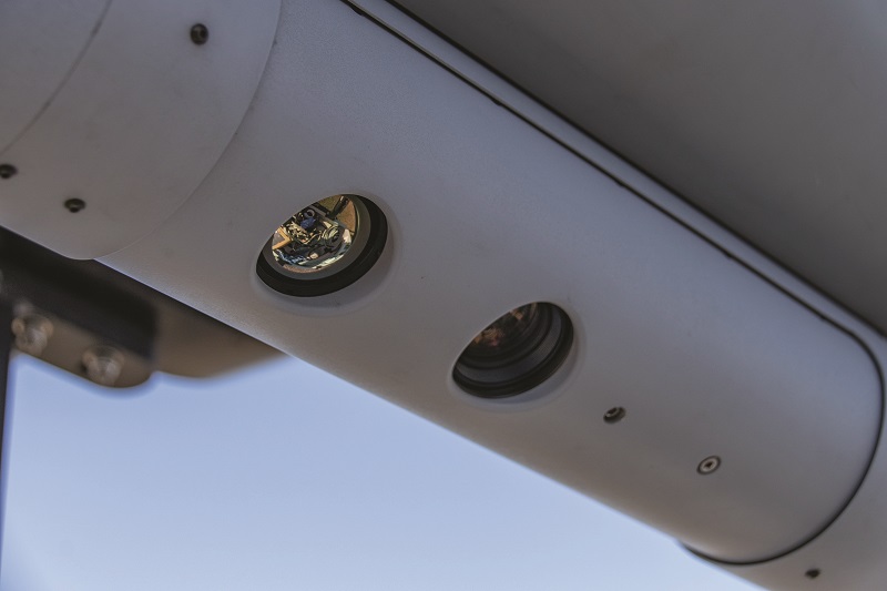
The ScanEagle VTOL’s nose is largely occupied by a gimbal, which traditionally integrates full-motion video cameras. This design choice, combined with the pusher propeller arrangement (which sees the engine and prop placed at the back), minimises the risk of occlusion from propeller blades and other devices, and maximises opportunities for clear, wide field-of-view (FoV) surveys.
“We have avoided standardising the kind of payload bay where gimbals get slung under the fuselage – common in other fixed-wing UAVs. Forgoing that for a design where the main payload forms part of the aerodynamic profile helps keep our OML [outer mould line] streamlined and aerodynamically efficient,” Hartley says.
“Through partnering Hood Tech Vision, we’ve made standard offerings of differently articulating and tilting gimbals, with both EO-only [electro-optical] and multi-sensor EO/IR [infrared] solutions for housing different sensors. The nose features our pitot-static system, with the pitot tube and static ports on the side of the payload module, as that ensures we’re getting the cleanest ram air, for the sake of getting accurate air data to the autopilot for flight.”
The fuselage’s cylindrical form factor enables a high degree of modularity, which most often takes the shape of conformal ‘slices’ containing extra subsystems to be inserted between standard sections of the UAV. These might, for instance, contain additional, mission-specific payloads, and hence sit between the payload nose and the main fuselage, although such systems can also integrate at the back.
A GNSS antenna installs atop the main fuselage, and aft of the fuselage, the fuel module contains the standard fuel tank, which runs into the propulsion module.
Body of Integrator
Like the ScanEagle, the Integrator is designed with payload and pitot static systems at the nose, and the propulsion module at the rear.
“We follow a similar subsystem layout as ScanEagle in that we want any optical systems as far away from the engine as possible to prevent occlusion- and vibration-related interference,” Todorov says.
“While that is true of almost any UAV design layout, our users will often integrate something like our Alticam 14 EO/IR turret, in which the imager’s optical zoom narrows down as precise as 0.13o for long-distance ISR, so it really is incumbent on us, as the platform designer, to mitigate as much vibration from being induced into the stabilised gimbal as possible.”
Integrator’s blended-wing body affords significant and advantageous internal space for fuel, with multiple different fuel-tank sections conformal with the OML and its aerodynamic profile, to tailor total fuel capacity for varying mission needs.
These tend to cluster around the main fuselage module, which again contains the aforementioned avionics module, as well as boards for power and signal routing from Integrator’s two payload bays (the second, larger payload bay is installed below the main fuselage section), the data link and actuator systems in the wings and winglets, and the propulsion and generator systems at the rear.
“Integrator also features an empennage connected to the fuselage’s wing roots via two carbon booms. It’s in the empennage where we typically carry transponders, and there is optional space for extras or other mission-specific systems,” Todorov notes.
A total of eight control surfaces are distributed across the wings and twin-tail empennage: two flaps and two ailerons in the wings, as well as two rudders and two elevators in the empennage. As with the ScanEagle, Integrator’s engineers tend to put their comms antennas (for radio and transponder functions) in the winglets to maintain the aerodynamic profile and keep the antennas spaced apart to optimise radio-frequency (RF) performance. However, the empennage provides additional locations suitable for antennas and data-link equipment.
“As far as space for mission systems goes, the payload bay under the fuselage serves as this wide-open, customisable sandbox – the aircraft is called Integrator for a reason,” Todorov muses. “Including the two main bays, there are five locations where we tend to mount payloads, and like ScanEagle, we can also engineer slices to modularly add on different sensors, data links, transponders and what have you.”
Both UAVs are mainly constructed using carbon fibre-reinforced plastic, and such is Insitu’s long history of working with such composites that it has amassed a diverse supply base for carbon parts. As with many of its subsystems, local suppliers generally form the first port of call for carbon fibre, and Pearce points to Decavo, Carbon by Design and Sekisui as some US-based suppliers that Insitu uses.
Mission systems
ScanEagle’s fuselage has a diameter of roughly 7 in (17.78 cm), so any sensor that can fit within that width can be installed at either the nose payload bay or in a slice module, so long as the slice maintains some empty space inside for routing wires and fuel lines, as well as for integrating ballast if needed to keep the CoG or CoB steady.
“Sometimes we need to do OML modifications, depending on the payload. For instance, ScanEagles sometimes fly with the NSP-3 synthetic aperture radar from IMSAR, and we can’t cram all of its components into a 5-7 in slice,” Hartley says. “So, instead, we hang its radar pod below the fuselage, with some of the core control electronics in a dedicated slice.”
The payload philosophy and history around Integrator is similar to ScanEagle’s, albeit with the addition of the rectangular, secondary payload module, which helps cater for the fact that “so many companies make sensors and comms systems for mission capabilities as boxes – rectangular things with 90° edges that don’t fit easily into Insitu’s predominantly cylindrical fuselages”, Todorov observes.
“So we offer a few different variants of that square payload bay, one of which has an outer skin that serves as a structural fairing, and another where all the structure-critical parts mount up into the aircraft, and the outer fairing for that version is non-structural, hence giving that base design a lot of flexibility for whatever customers want to put into the bay. Being a simple, rectangular component also allows us to customise for different internal mounting or cooling needs fairly easily too.”
Also key to this has been judicious selection of components such as electromagnetic (EM)-shielded connectors and cables to minimise the RF emissions of both UAVs, as a sizeable portion of Insitu’s customers fly highly EMI-sensitive solutions, such as signals intelligence, non-communications-based signals and communications relays.
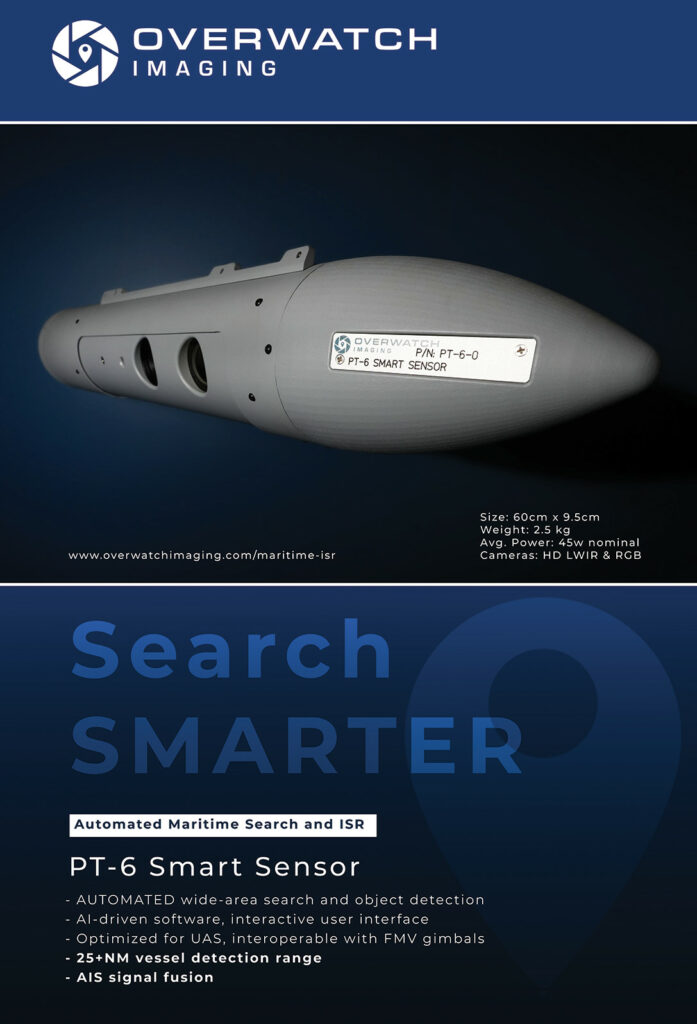
In addition to the wide range of EO and IR cameras compatible with the nose turrets of both UAVs, today’s ecosystem of core payload offerings encompasses numerous high-end systems embedded with critical image-processing algorithms for actionable wide-area surveys, including Overwatch Imaging’s PT-6 EO/LWIR maritime gimbal, Sentient Vision Systems’ ViDAR (typically integrated as a slice), and Logos Technologies’ wide area motion imagery (WAMI) and middle wavelength infrared (MWIR) sensors.
Structure and hull
The defining factor behind the structures of ScanEagle and Integrator is the highly energetic catapult-launch event that has kicked off the majority of their missions over the years. The shock and force of catapult launching places a minimum structural-strength requirement across numerous key points of both aircraft.
As a result, the shapes and structures of both UAVs have remained mostly unchanged over their years of development, with the most noticeable evolutions including ScanEagle’s move from a fixed nose globe turret to an articulated dome that can roll 360o. The remainder have been minor tweaks for qualities such as structural strength, vibration damping and the packaging of internal systems.
While the catapult launch is far less vital a consideration for customers relying on the modern VTOL-capable version of either UAS, Insitu is determined to maintain backwards compatibility with the SkyHook, just in case customers need to use them in rare instances.
“We use some complex, finite element analytical tools to generate effective heat maps of any mechanical stresses that get communicated through the monocoques of our aircraft during launch and recovery, and we know from routine analysis that loads during cruise are very stable and straightforward,” Todorov says.
“It is in launch and recovery where we get highly dynamic forces acting on the UAVs, and load-paths changing very rapidly, and coming in from directions that you might not normally expect. We use all that data to inform our carbon lay-up structures, and from there it’s just a matter of close interaction with and deep trust in our composite suppliers.”
Pearce adds: “We control our part designs and stocks to very tight tolerances, and there is a lot of ‘coupon testing’, where we put samples of materials through rigorous validation processes. When we release a design for a structural part every numerical parameter that can be specified, verified and validated in the material is specified, verified and validated at Insitu.”
Significant interactions tend to follow the validations of structural parts to achieve secondary (though still important) goals such as manufacturability and weight optimisation. Despite the minimum structural strength requirements, Insitu’s engineers constantly evaluate every structural part in terms of the mathematical relationships between grams added onboard either UAV and the corresponding number of minutes that endurance would shrink by.
GNSS and MEMS
Insitu primarily partners NovAtel for its navigation systems, with a variety of GPS and multi-constellation GNSS receivers (with MEMS IMUs) from the Hexagon company having been installed on the ScanEagle and Integrator over the years, largely for their high positioning accuracy.
“When you look at the numbers, say the level of navigation accuracy gained from flying with a FOG over long periods of time, FOGs don’t have such a huge performance advantage that they’re vital to the missions we fly,” Todorov says.
“What’s more interesting to our users are parameters like the geolocation estimate accuracy of the payload sensor’s point-of-interest or the target location error. Our level of drift would not suddenly become commensurately better with a FOG or RLG to the point that we would be happy to fly and navigate on inertial data alone. A combined approach of GNSS, IMU and multiple other sources for PNT that we can fuse, and evaluate against each other, is the best solution.”
A question of autopilots
The autopilot systems integrating these navigation components differ considerably between the two UAVs. On the ScanEagle, autonomy is enshrined within an autopilot proprietary to and originating within Insitu. “We’ve integrated external sensors such as accelerometers, gyros, pitot static systems and other sensors into that over the years,” Hartley says.
“Options were limited 20 years ago, particularly in terms of the SWaP that Insitu’s founders wanted their autopilot to conform to, so they decided to make one on their own, and they were successful. A lot of the original ScanEagle autopilot code and logic was written by Dr Tad McGeer [founder of Insitu Group, and now founder and president of Aerovel] himself.”
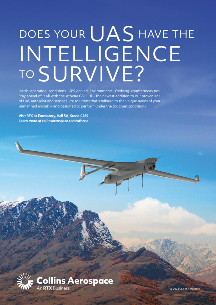
The Integrator’s autonomous functions, by contrast, are powered by the Collins Aerospace Athena autopilot.
“It is generally associated with very large and high-end UAVs. When you run the Athena software, combined with the standard-issue hardware, and an INS [inertial navigation system] that typically comes with it, those provide a very comprehensive flight-control systems network,” Todorov says.
“Collins has a really sophisticated test suite, including Monte Carlo simulations that they run against all of Athena’s code. They focus with similar dedication on very robust enclosures to keep their ASICs safe and sealed, and they use advanced, embedded Kalman filtering for taking in multiple PNT-critical data sources, and intelligently recognising and rejecting erroneous inputs.”
A plan for every servo
A detailed system of fault trees and similar reliability analysis tools are routinely leveraged to inform Insitu’s minimum requirements on servo lifetimes and tolerances. With these, the company has periodically looked across the industry to identify ideal matches, although Todorov and Hartley note that, historically, a mixture of hobby- and industrial-grade devices were often the best that could be found.
As well as comparing unfavourably to the highly reliable and SWaP-optimised servos made especially for the uncrewed market today, these would rarely come with any reliability data, so Insitu has long since developed its own internal testing processes for evaluating servo MTBF.
“Depending on the criticality of the application, we can tolerate some margin for failure in the control surfaces. If we lose one, we can often maintain normalised flight control, but in missions where we can’t tolerate even one failure, the MTBF estimate is very useful for informing servo inspection, testing and replacement schedules for servos,” Todorov notes.
A touch of FLARES
Programming and testing has contributed to FLARES’s development in some surprising ways, as Hartley relates: “In a computational sense, FLARES is surprisingly simple, because the multicopter’s manoeuvres aren’t complicated. The really interesting launching code is on the ScanEagle and Integrator’s side: we’ve added logic to both flight-control systems, such that the operator indicates in pre-flight planning whether they are catapult-launching or FLARES-launching.
“If it’s the latter, the aircraft is tasked with detecting when FLARES spins up its rotors, when it ascends, when it reaches the ideal height for mission commencement and, most importantly, when it starts dashing to give a viable speed for release and hence launch. Then, the ScanEagle starts running queries as to whether it is moving at a good airspeed, a good altitude – essentially, are all the conditions right to support a drop into free, fixed-wing flight?”
Once the launch conditions are acceptable, the operator is notified, who then provides a green-light trigger to the autopilot to begin the automated launch sequence, allowing the UAV’s powertrain to start and FLARES’s docking clamps to be released. In turn, FLARES keeps track of key timing and altitude stepping points through its internal clock and altimeter respectively, which trigger it to transition from ascent to dash.
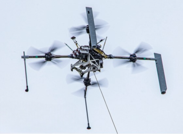
Despite its metallic appearance, the FLARES airframe is mostly built from carbon fibre and it features four rotor arms. In FLARES 2, each one is designed with a ‘leg’ or strut for landing, while in FLARES 3, two of the legs are designed as fin-like components for greater stability during the dash phase of launch.
Each arm on FLARES 2 integrates two electric motors and propellers in a coaxial configuration. In FLARES 3, this is doubled, meaning two motors per prop and 16 motors in total, for extremely high redundancy in launch and recovery, and thus minimising the chance of ScanEagle or Integrator suffering damage due to a motor failure. The four arms run into the central hub, where FLARES’s Lithium-ion batteries, ESCs (with Currawong’s Velocity ESCs among those used), autopilot and flight sensor package sit.
A few components outside of the multirotor include the capture rope for recovery, an automated winch that installs at the ground to lower the captured UAV downwards for safe and steady recovery, and a mast-like, proprietary, mechanical anchoring point to fix the rope to the ground, referred to by Insitu as MARS (mast-augmented recovery system).
“That differs from SkyHook in the sense that it folds very neatly into an 80 in storage container, hence that mast structure can be transported around in a much more mobile way, and secured into most terrains to ensure a fixed position for the bottom end of the rope during recovery,” Pearce says.
In addition to the redundancy espoused as a vital target over iterations of FLARES, power efficiency is critical, with Hood Tech Mechanical’s credo of ‘hover at half power’ indicating that it designed the multirotor to be capable of achieving hover with half of its maximum thrust capacity while still carrying a ScanEagle or Integrator underneath.
Hartley says FLARES can do a better job of gust rejection and operations in high sea environments than most integrated, VTOL-transitioning UAVs. It can maintain stability against winds of up to 30 knots and gusts up to 10 knots by virtue of its greater size, power and authority in pitch and roll than one would find on an aircraft-installed VTOL system.
Insitu’s engines
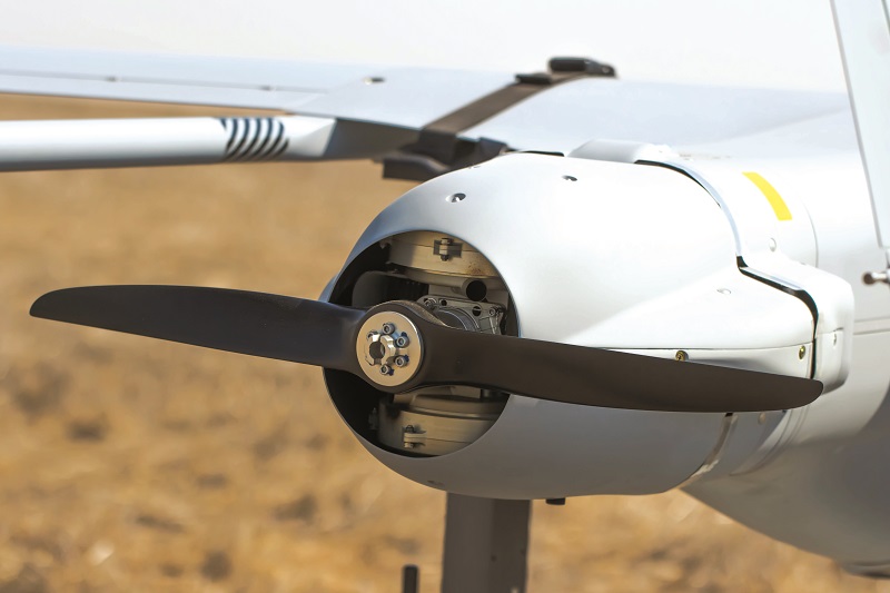
While both UAVs operate on the basis of two-bladed, carbon-fibre pusher propeller drives, their powertrains start to differ greatly from each other as one moves forwards into their engines.
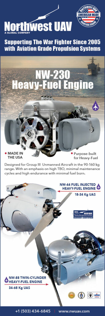
As our long-time readers will know, the ScanEagle comes with a few engine options, including: a 28 cc single-cylinder, originally from 3W International, but heavily modified by both Insitu and NWUAV; the NW-44, designed and produced by NWUAV (detailed in Issue 6); and the N20, co-designed by Insitu and Orbital UAV (detailed in Issue 8).
“Which engine is ‘better’ depends hugely on where and how the end-user is operating. As the gross takeoff weight on different ScanEagle configurations has increased, the N20 can provide a degree of higher value among customers with greater payload requirements, and significantly higher power generation than our traditional, 28 cc engine,” Hartley says.
“We have a gasoline, carburetted version of the 28 cc engine and an EFI, heavy fuel version, which provides some versatility, although the N20 was designed to run especially efficiently on heavy fuel via its compressed-air, assisted direct-fuel injection. We also have specific customers who prefer the NW-44.”

The NW-44 and N20 have been covered extensively in this publication, and were among the first UAV-specific engines designed with eventual FAA certification in mind. Both of these are spark-ignited, naturally aspirated two-strokes, designed around single cylinders and using electronic fuel injection (EFI), which have been optimised to run on multiple different fuels, including gasolines, Jet-A, JP-5 and JP-8. The NW-44 is a 43.6 cc product with an all-up weight of 4.3 kg, a maximum power output of 3.5 hp (2.6 kW) at 7250 rpm and a TBO of up to 500 hours. The N20 is a direct-injection engine, displacing 49.9 cc, producing 2.95 kW with a total weight of 4.97 kg.
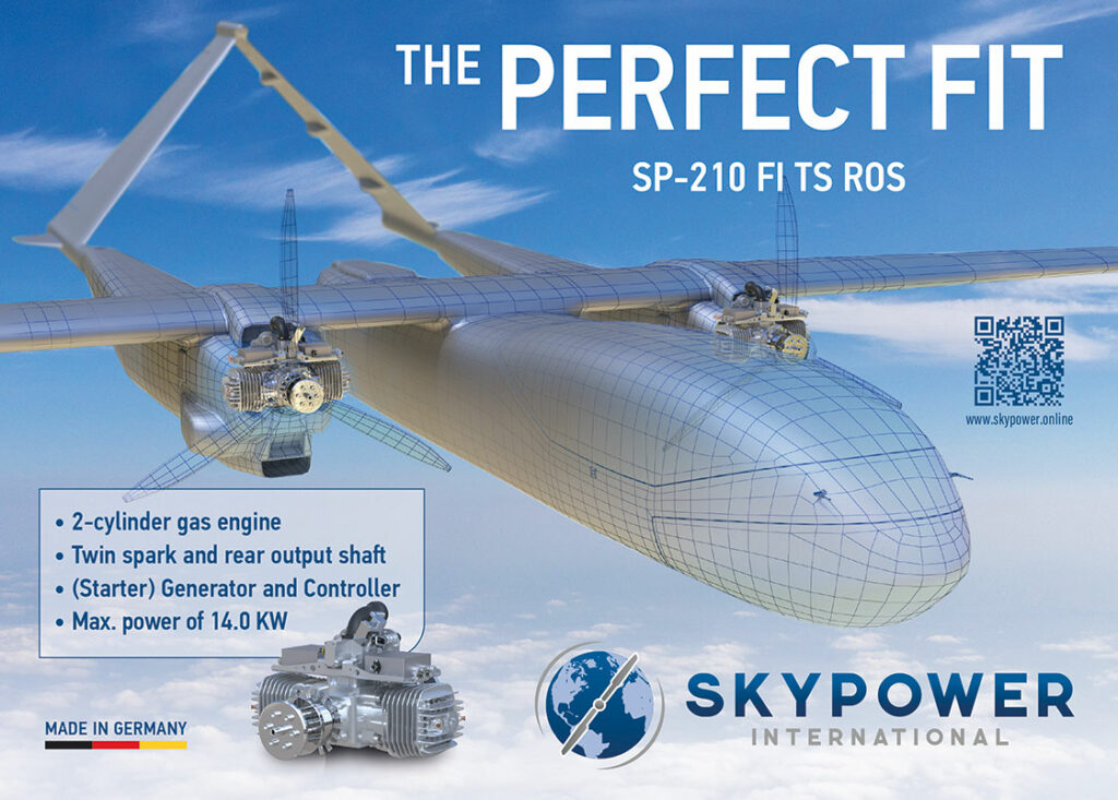
The Integrator, by contrast, comes with just one power unit option, developed in-house and referred to as the Integrator PMU (Propulsion Module Unit), which is described by the company as being in its third version (V3).
Details on this engine are kept tightly under wraps by Insitu’s flight sciences team, but the company tells us that like the ScanEagle’s engines, it is a spark-ignited, air-cooled two-stroke, specifically designed for heavy fuel operations (particularly JP-5 and JP-8).
It is configured with two cylinders rather than one (arguably an inevitable consequence of needing more power to shift the far heavier of the two UAVs), and it has been optimised to fit within the specifications laid out in original STUAS competition that spawned the Integrator over a decade ago.
“We started with a blank sheet design, initially configured for running on gas or avgas, just to speed up the prototyping process, and evolved that into a heavy fuel engine after the programme was awarded,” Todorov says.
“The PMU V3 is a wholly original Insitu engine design, maintained and iteratively optimised over the last 15 years, with specific improvements in durability, reliability, shaft power, and ultimately electric power for payloads being key targets.”
More power, more footprint
Fuel runs to the PMU from carbon-fibre tanks integral to the Integrator’s structure, with baffle designs to maintain centres of weight and balance during fuel drawdown during flight. Through the shaft power driving an alternator, a standard electricity supply of 350 W is provided from the PMU for payload use.
“We’ve done a lot on both platforms to keep separate, segregated payload power buses from our flight control buses, so payload demands from a power standpoint do not impact either of the UAVs’ ability to constantly maintain normal flight,” Hartley says.
Hartley, Todorov and Pearce note that customer demands for power continue to rise, which has contributed to the integration of more capable engines and generators over the years, and vindicated the choice to design Integrator’s airframe with structural margins, along which the fuel tanks could be expanded.
“Payload power growth has always been on Insitu’s roadmap, and we approach Integrator’s engine development almost like car companies do – as soon as we finished V3, we almost immediately started work on its next variant, based on industry trends we were seeing, even though the need wasn’t explicitly out there yet,” Pearce adds.
Insitu is now conducting development and tests of a 4th generation PMU in response to increased customer demand for payload power, in pursuit of missions with more sophisticated maritime patrol radars, signals intelligence payloads and so on.
“Fortunately, while copper is copper, there have been great advances in material science that allow you to lighten, strengthen and optimise the supporting structure around your copper wiring by using more advanced alloys and whatnot,” Todorov notes.
“But it is a gradual process. With engines, you don’t want to change parts that are working, because there are so many ways to break your engine along the way. However, there has undeniably been great advancements over the years in alternators and generator control units, so we’re in the down-selection process for components to go into the V4 PMU.
“Give it a year or two, and we will likely have made some interesting choices on that engine, which we could then tell you a lot more about.”
Radio systems
As mission-specific as data links are, ScanEagle and Integrator can come standard with Freewave radios for their C2 links, while using L3’s BANDIT transceiver to power the higher-bandwidth payload data link. Persistent Systems’ Wave Relay 5 (a version of its MPU5, designed as a node for embedding on uncrewed vehicles) has also been used.
“Those connect to custom PCB antennas we’ve designed for compatibility with the radios and our SWaP limits,” Hartley says. “We have retained an RF engineering team at Insitu to research and guide all our RF design decisions, with lab set-ups for developing and testing antenna components, including a small anechoic chamber for modelling the performance of PCB antennas in relation to other surfaces.
“Once we’ve characterised an antenna, and reached the point where we need a system-level evaluation, we will usually contract the final tests to a third-party laboratory, and our RF team will go there to guide testing and analyse the results in person.”
In addition to its comms radios, a variety of transponders have been installed on the Insitu platforms over the years, and the company notes that Sagetech is its typical go-to (particularly for ScanEagle). Usually, a Mode 3 C-type transponder is chosen to broadcast the UAVs’ altitudes and a four-digit octal identification code, although ADS-B systems are also supported for when the broadcast of identification, position, altitude and velocity data is a requirement.
Ground control stations
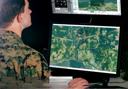
ScanEagle is typically preprogrammed, monitored and controlled during missions via the I-MUSE (Insitu multiple UAS software environment) GCS software, which was developed in tandem with the UAV’s autopilot software, and it has been continually updated over the years while remaining backwards-compatible with all configurations of ScanEagle.
I-MUSE serves as the base software of ScanEagle’s C2 structure, allowing for mission planning, launch and recovery, aircraft and multi-aircraft tasking, target tracking, automated-target following and payload operation, its map indicating waypoints, targets and aircraft tracks.
That map provides the pilot with situational awareness information via visual displays of terrain, obstacles, altitudes and other data. It also provides multiple pre-flight, post-flight and emergency electronic checklists, and a means for point-and-click real-time control and monitoring of the aircraft.
Hartley describes I-MUSE’s interface as “having been designed by engineers, which means its layout is rich with detailed engineering panels that you wouldn’t normally find in other common operating platforms for UAVs.
“There are pros and cons to that. Our customer base has become very familiar with it, and they get to do a lot of things via I-MUSE that they wouldn’t get to on other uncrewed systems.”
These include the development of deployment- and payload-specific UIs to reduce operator workload and fatigue while providing the best actionable intelligence – the operator essentially draws lines for flight paths and target paths, and specifies which one to follow, enabling the multitasking of operational requirements.
Rather than I-MUSE, Integrator uses Insitu’s Windows-based INEXA Control suite as its GCS software and is compliant with NATO STANAG 4586 on the interoperability of UAV control solutions (covering requirements in C2, human and machine interfaces, and data links, while also defining requirements in architectures, interfaces, comms protocols, data elements and message formats), as well as STANAG 4609 on digital motion imagery.
“It is a multi-purpose tool, covering mission planning, C2 and flight operations, and it can be networked across multiple GCS computers. We have demonstrated simultaneous control of multiple uncrewed platforms through INEXA,” Todorov explains.
“Like Integrator, it is a highly modular interface, which users customise as needed using a system of vehicle-specific Platform Kits and vehicle-agnostic Mission Kits, which are essentially plug-ins created via Insitu’s SDKs that account for the specifics, real-time conditions and dynamics of each uncrewed vehicle and mission type registered in our system.”
Those can include air vehicles’ specific acoustic profiles to visually project audio-detectability onto the operator’s moving map display, thus ensuring the vehicles remain acoustically undetectable. Additionally, for safe integration into congested airspace, INEXA’s airspace management plug-in displays other air-traffic tracks (including air speed, heading and altitude) and alerts operators to unsafe headings, based on mid-air collision volumes.
Through Insitu’s parent company, Boeing, INEXA has incorporated software features such as Boeing 777-style air speed and altitude gauges, as well as what Todorov refers to as a net-centric, plug-in based, service-oriented architecture, capable of synchronising events, video and communications across myriad computer interfaces for shared operations.
“INEXA’s AVOS [Augmented Video Overlay System] has been designed to allow video to be overlaid atop of satellite imagery, to display full-motion video on a map where the UAV is geographically in real time. It can also display all other sorts of incoming payload data, such as locations of tracked targets or signals intelligence,” he adds.
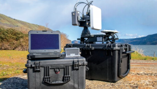
While customers have historically used many different control stations to oversee ScanEagle and Integrator missions (including fixed consoles in ships and ground bases), Insitu has converged over the last five years around its aforementioned CGCS, which consists of a ruggedised laptop capable of operating in climates from -32 C to 49 C, running either I-MUSE or INEXA, and swapping various radio modules in and out.
The system complies with STANAGs 4586, 4609 and 3607, runs on a 20-35 V DC power input (from batteries, shore power, grid power or even a road EV) and can link to the customer’s UAVs via ground antennas of various ranges up to 130 km, with S-band, L-band and C-band data links available as standard.
“As a control console, we’ve designed it to be as open as possible to non-Insitu UAVs and computer peripherals. If the end-user wants to wirelessly connect a field tablet computer to it, or plug in five huge monitors and joysticks, they can,” Hartley says.
“As we integrate different radios and data links for our systems, or for others, it is just a matter of putting those in ruggedised boxes, and connecting them with standard power and data interfaces via our Device Control Unit, which is what we call the central computer block in the CGCS.”
Future
Looking back over the way ScanEagle and Integrator have evolved since the early 2000s, one finds that Insitu’s UAVs entered life as disconnected systems, owned and operated outside of their users’ circles of control. But, as data links, networks and the need for multi-domain solutions arose, the Washington company has toiled strenuously to reimagine its aircraft under the lenses of connectivity and standards compliance.
“As people’s understanding of what small UAVs can do has advanced, so too have we seen opportunities to leverage technological advancements to extend the range of our platforms, both in terms of increased endurance, longer-distance connectivity and more robust autonomy,” Todorov says.
On the last of these points, Todorov, Hartley and Pearce note that considerable work has gone into each stage of the extended logic tree that the ScanEagle and Integrator go through when the operator triggers a high-level function, encompassing both normal and emergency flight behaviours that they can engage in. They add that while many mission-specific autonomy engines are coming to market, both open-source and otherwise, system-wide vehicle autonomy is just as critical for the utility and survivability of uncrewed systems.
“That is really what we see as the future of UAV engineering: users have increasing expectations around the aircraft’s ability to sense its environment and react accordingly, including maintaining normal flight control, without needing its operator’s permission to keep itself flying safely,” Todorov says.
“With that in mind, we are receiving more requests from other Group 2 and Group 3 UAV manufacturers to licence some of our autonomy and automation subsystems, including I-Muse and INEXA.
“So, as large as our ecosystem of suppliers is across North America, and as important as they will continue to be in our capacity as a provider of global ISR solutions and services, going forward we will likely take an increased role in the uncrewed industry as a supplier ourselves, providing the mission and vehicle systems we have innovated here back out to this industry that has supported us so consistently for so long.”
Key specifications
ScanEagle VTOL
- ScanEagle VTOL
- Fixed-wing
- Spark-ignited engine
- Gasoline & heavy fuel
- Wingspan: 3.1 m
- Length: 1.71 m
- MTOW: 26.5 kg
- Max payload weight: 5 kg
- Max payload power: 150 W
- Maximum endurance: 18 hours
- Ceiling: 5950 m
- Max horizontal airspeed: 41.2 m/s (148.32 kph)
Integrator VTOL
- Fixed-wing
- Spark-ignited engine
- Heavy fuel
- Wingspan: 4.9 m
- Length: 2.5 m
- MTOW: 74.8 kg
- Max payload weight: 18 kg
- Max payload power: 300 W
- Maximum endurance: 24 hours
- Ceiling: 5944 m
- Max horizontal airspeed: 46 m/s (165.6 kph)
Some key suppliers
ScanEagle-specific
- Autopilots: In-house
Integrator-specific
- Autopilots: Collins Aerospace
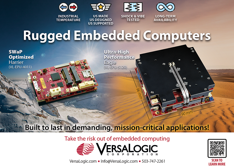
- Embedded computers: VersaLogic
- Engine: In-house
- Engine: NWUAV
- Multi-sensor gimbals: Overwatch Imaging
Both UAVs
- Antennas: In-house
- Antennas: Antcom Corporation
- Antennas: Radiall USA
- Antennas: NovAtel
- Carbon composite: Carbon by Design
- Carbon composite: Decavo
- Carbon composite: Sekisui Aerospace
- Gimbals: Hood Tech Vision
- GNSS: NovAtel
- Launch and recovery systems: Hood Tech Mechanical
- Launch and recovery systems: Zepher
- Multi-sensor gimbals: Overwatch Imaging
- Radios: Freewave
- Radios: L3
- Radios: Persistent Systems
- Synthetic aperture radar: IMSAR
- Transponders: Sagetech
- Wide area optical sensors: Sentient Vision System
UPCOMING EVENTS


