


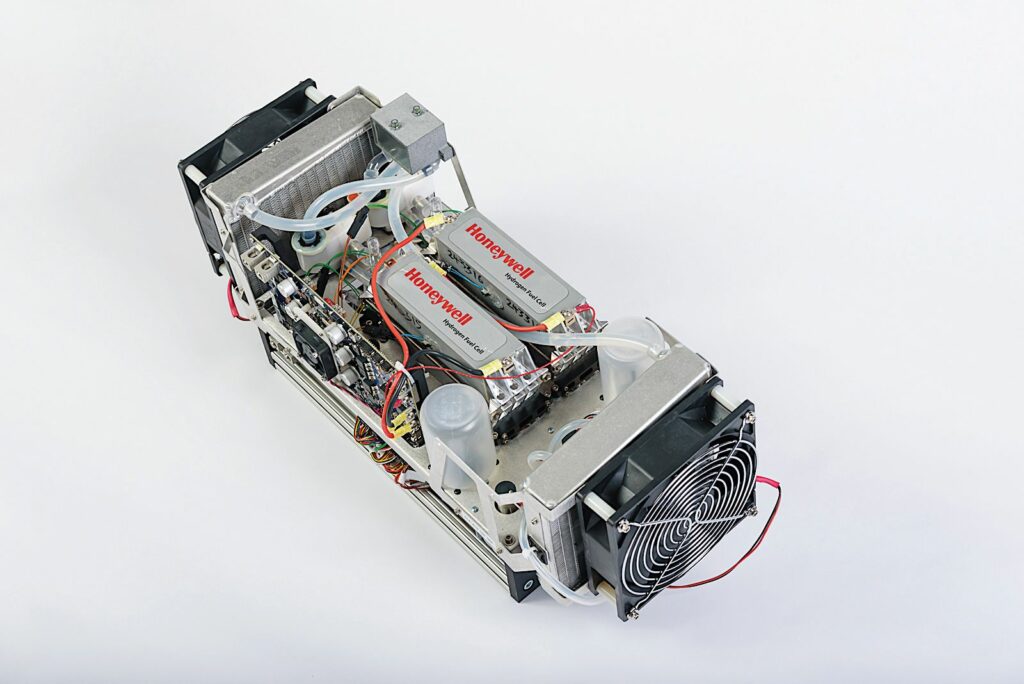
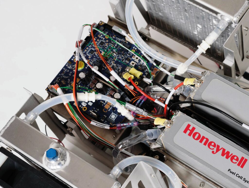
Honeywell 600U, 600U-HV and 1200U fuel cells
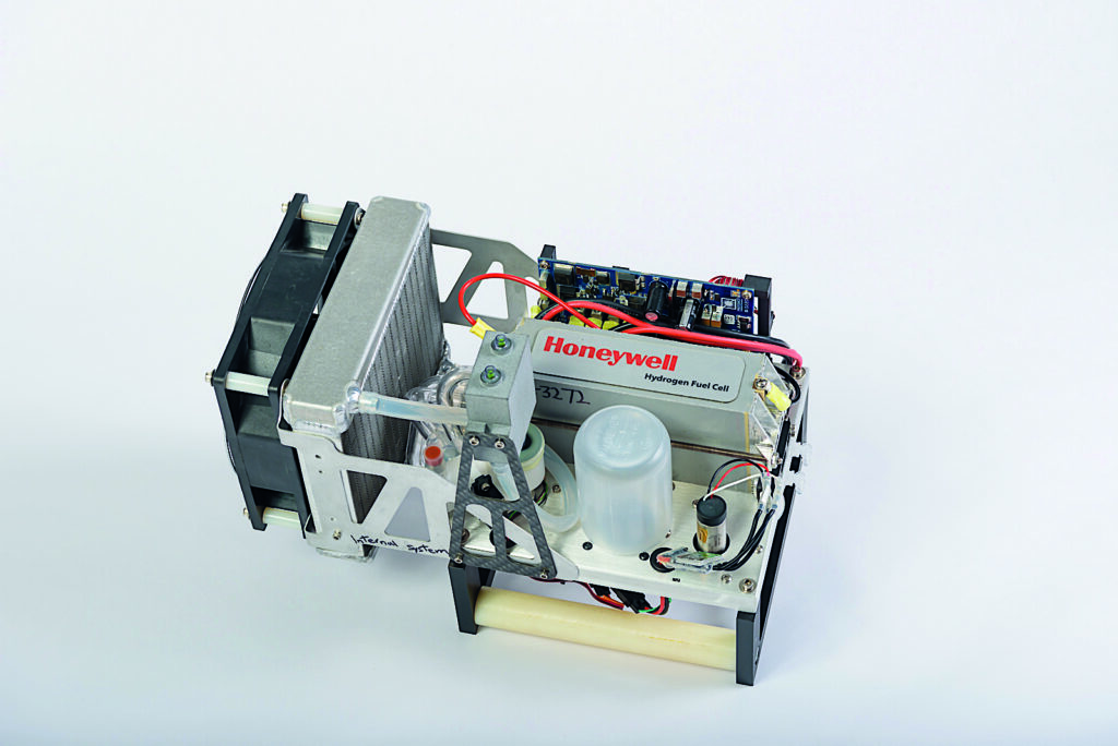
(Images courtesy of Honeywell)
Hydrogen Update
Rory Jackson looks at how this PEM technology has been developed since Honeywell took it under its wing
In UST 14 (June/July 2017) we featured the hydrogen fuel cell from the Protonex Technology Corporation, which at the time was principally used by Insitu as a swap-in replacement for the ScanEagle’s two-stroke spark-ignited engines from Northwest UAV and Orbital UAV.
Since our first article on the technology, its commercial success has continued. More than a dozen UAV platforms and some UUVs now use the Protonex-designed PEMFCs, including the Solus-LR LUUV from Cellula Robotics (discussed in detail in UST 30, February/March 2020), which is still a customer. We are therefore revisiting the technology to examine the current state of its design, subsystems and operation under its Honeywell ownership.
At present, Honeywell offers two fuel cell products: a 1200 W system called the 1200U, and a 600 W system that comes in two versions. Of these, the standard-issue 600U is designed to output power at 12 to 33.6 V DC, with 30 A of continuous current up to peaks of 50 A, while the 600U-HV is designed for voltages from 8 to 58.8 V, and currents of up to 60 A continuously and 100 A at peak. Both can be referred to collectively as the 600U.
The 600U weighs 1.8 kg, while its high-voltage variant is 1.9 kg. The 1200U weighs 4 kg, and while the 600U communicates over an RS-232 connection with its host platform’s autopilot, the 600U-HV and 1200U do so over RS-422 or CAN bus. All three have a time between overhauls – defined in this instance as the interval between replacements of the balance of plant (BoP) – of 1000 hours, and a service life of 3000 hours.
“We’ve gone through extensive testing as it pertains to our different customer groups,” says Phil Robinson, senior director of engineering for zero-emissions aviation at Honeywell Aerospace (formerly VP of defence power systems and then of unmanned systems at Protonex, and general manager of the Ballard Unmanned US subsidiary as well).
“For our Department of Defense (DoD)customer, for example, we’ve put fuel cells through Mil-Std electromagnetic testing to ensure we don’t interfere with other systems, as well as shock and vibration testing mainly for rough shipping, and even orientation testing where we show the fuel cell works for a period of time upside down or in different gravity conditions, despite the fluidic challenges of maintaining stable hydrogen, oxygen and waste water flows amid changes in gravity.
“On that note, we have also made a unit for an uncrewed space launch vehicle, which underwent immense g-forces during lift-off, so we know how to make fuel cells for punishing applications.
“We’ve put a lot of expertise and investment into hydrogen test capabilities, and Honeywell has considerable internal facilities and knowhow for testing to FAA certification. We’re only now beginning to understand what BVLOS UAS certification requirements will be, but we’re well-prepared for whatever the case.”
Architecture and operation
Around the fuel cell stack is a BoP consisting of control electronics, a blower, humidifier and other electronic and electromechanical parts. The 600U measures 24.1 x 17 x 14 cm, while the 600U-HV is 23.1 x 15.5 x 13.7 cm, and the 1200U is 43.2 x 26.67 x 16.5 cm.
Each is built largely as a single, monolithic unit that is integrated for simplicity as well as to minimise cabling requirements, but it can also be designed as a cube-shaped system for multi-rotors or as a longer, thinner package more suited to fixed-wing aircraft. There are several systems for mounting the fuel cells in different ways, the most widely used being an aluminium tray with mounting holes on its top, bottom and sides for bolting into any fuselage.
While the overwhelming majority of parts in the 600U and 1200U are made in-house by Honeywell or its partners, one item that Honeywell does not make are the membrane electrode assemblies (MEAs), given the delicate balancing of materials and understanding required to fabricate such items.
“Even when we were still Protonex, we used a COTS automotive-grade MEA,” Robinson recounts. “When we were part of Ballard, they made us a special custom MEA that was optimised for UAVs, and although we’re now part of Honeywell, we continue to use that MEA primarily; it’s a five-layer component supplied by Ballard.”
As discussed in UST 14, those five layers consist of a central Nafion membrane that’s responsible for conducting protons and hence outputting current. They are coated on each side with a catalyst layer made from carbon black and platinum, and with a carbon gas diffusion layer over each coating.

Also, being a liquid-cooled fuel cell, it is a closed-cathode system, meaning the oxidant and coolant flow channels are separate rather than being the same. That gives advantages such as more optimised and responsive cooling and oxidant supply rates, easier humidity control, less need for current pulsing, and a wider environmental operating range than open-cathode PEMFCs – the 600U and 1200U are recommended for use between 5 ºC and 45 ºC, compared with an upper limit of 35 ºC in most open-cathode systems.
“That’s a very conservative environmental operating range,” Robinson adds. “We’ve done a lot of testing down to -20 ºC. Also, the MEA has some inherent features that are optimised for UAV operations.
“Consider a typical automotive PEM fuel cell stack, you tend to run it very conservatively. Because you don’t pull a lot of power from it, you operate it fairly high on the voltage-current curve. You do that because you want it to last tens of thousands of hours, maybe even 100,000.
“The thing about this market is that nobody flies a UAV for 100,000 hours. Even the most robust commercial uncrewed aircraft will undergo either an overhaul or potentially an ‘unplanned landing’ before then, or just as likely they’ll be obsolete well before the PEMFC nears that lifespan,” he says.
That enables the Honeywell fuel cell stacks to be run far harder in terms of current than a typical automotive stack, meaning more power versus weight. The MEA is optimised to withstand the resulting environment and still achieve its 3000 hour service life.
Another key operational consideration is start-up time. PEMFCs have an inherent advantage over other types such as solid-oxide fuel cells, which can take 20-30 minutes to warm up sufficiently for take-off. The liquid circulation inside the 600U and 1200U however enables a warm-up time of about 30 seconds, during which the control systems initialise, any leftover water or hydrogen is purged, and the heat inside the stack reaches its preferred operating point.
Robinson adds that when air-cooled fuel cells aren’t running, their MEAs are typically exposed to the atmosphere, as air tends to sit and flow freely in the coolant-oxidant channel. That risks drying out the MEA, increasing their start-up times because the internal environment must be re-humidified to prevent damage during power generation.
“A liquid-cooled stack is completely sealed though, so the water you left in there the last time you shut it down is still there when you fire it back up,” he explains. “No humidification period is needed during start-up, which is quite a bit more convenient not only for the DoD, which often wants to fly at a moment’s notice, but for any user looking to maximise uptime.”
Fluid management
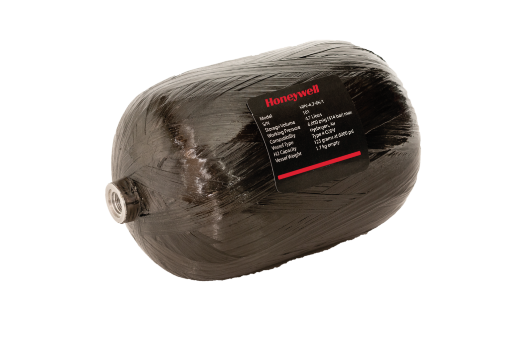
Hydrogen typically flows at 1 bar into the fuel cell system, via the BoP which contains a system of channels and valves for delivering hydrogen as needed for stoichiometric balance of hydrogen and oxygen. For early integration programmes, Honeywell also provides a carbon-overwrapped pressure vessel as well as the pressure regulator for stepping the stored hydrogen down to 1 bar.
“In Europe, that’ll be a 5000 psi tank, or around 350 bar; in the US it’ll be a 6000 psi or 414 bar tank, simply because of differing commonly available hydrogen cylinder pressures in Europe and North America,” Robinson says. “Our pressure regulator and related components are rated for 414 bar, so they’re safe for use with European and US tanks.
“We also supply a hydrogen fuel level sensor. This is a pressure gauge designed with an electrical interface to run to the aircraft so that the remaining quantity of hydrogen gas can be measured and communicated to the operator at the GCS, as well as a fill coupling so that swapping the tank or bringing the UAV to a refill station is an option for replenishing the hydrogen.
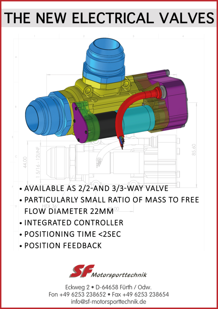
“At the moment, we’re working with two pressure regulator companies, and one good thing about both systems is that they’re multi-stage regulators. Since they’re going to take gas from 5000-6000 psi down to around 20 psi, any company trying to do that with one or two stages will struggle to keep the output pressure stable over a wide input pressure range. In addition to avoiding drift, they’re small and lightweight – they were designed expressly for UAVs.”

As well as delivering hydrogen, the fuel cell stack must intermittently purge waste water and nitrogen through an exhaust valve. This process can also release a small amount of hydrogen, and in automotive fuel cells a hydrogen recirculation pump is often installed to capture expelled hydrogen gas and send it back to the system’s input point, to prevent fuel waste as well as potential safety hazards.
“We have a proprietary hydrogen recapture method that does not require a pump,” Robinson says. “We route purged hydrogen through some valves and ballasts that allow us to achieve a 99.6% hydrogen utilisation rate with no parasitic loss.”
For air intake, a proprietary blower designed in-house is used, since as far as the team knows, no blower exists that is light enough to be used on a UAV while still providing enough air pressure and throughput to run the closed-cathode fuel cell. It is designed into the fuel cell system enclosure, and features an integral filter for preventing contaminants entering the oxidant feed.
“An open-cathode stack just uses a fan to pull air through the cooling and oxidant paths simultaneously, but we need to force it through flow fields in the plates of the stack, so we need more pressure, hence the need for the blower,” Robinson explains. “We are also doing r&d with newer things such as Honeywell’s turbo-compressors, which we think are going to bring really interesting, potentially more powerful capabilities in future generations of the fuel cell.
“The blower is naturally the most energy-parasitic component on board – it represents more than 60% of the total parasitic load – but reducing the parasitic power relative to the airflow and pressure is a consistent focal point of our research. And of course, with UUVs such as Cellula’s, the oxygen comes from a tank, so in situations like those the very minor concern of the blower is replaced by more of a metering concern, as with the hydrogen.”
Electrics and electronics
The fuel cell controller is a microcontroller engineered in-house and based around an STM32 processor from STMicroelectronics, which is highly centralised to minimise weight and complexity. It actively manages all the BoP’s components and hence the various functions that are key to the PEMFC’s operations – including purging, current pulsing and managing the cell-by-cell voltages – by sensing when they are needed and executing them accordingly.
“Although we worked with distributed control systems at Ballard, UAVs can’t really afford the weight of anything other than a centralised control architecture,” Robinson says. “Our software on the other hand is highly modular and object-oriented, which allows us to iterate new versions very quickly or trial new components such as different fuel monitoring sensors, fluid valves and coolant pumps.
“Most of our functions are standard, closed-loop PID controls, which is useful for instance in the thermal management target of keeping the internal environment at 60 ºC. If it drifts above that, the controller pumps water faster to the heat exchanger, or if it drops below that it sends some water to bypass the heat exchanger. It does the same for maintaining humidity, stack health, purged hydrogen recovery, waste water expulsion and related parts.”

As well as running all the valves and pumps, the blower and so on, the fuel cell controller also runs the BMS. The fuel cell system almost always integrates a hybrid battery, virtually always a lithium-polymer or lithium-ion battery, which takes the current peaks, troughs and sudden transitions demanded by the UAV motors and outputs a stable voltage and current to the UAV while gently ramping the fuel cell output up or down.
The BMS also takes into account battery state of charge (SoC), battery voltage and current, and load (UAV) voltage and current. That helps with managing the fuel cell because it provides a window into how the PEMFC itself needs to be managed.
Core data points such as the battery’s health, SoC and cell temperatures can be monitored closely so that the fuel cell’s operations can be adjusted to keep these within normal parameters, batteries being a rather more hazardous component than PEMFCs.
“The battery also lets us output a reasonably high voltage to the UAV so that the cables running to the electric motors don’t have to go through a DC-DC converter,” Robinson notes. “If they do, you or the customer then have to size the converter to the maximum load power, rather than to the maximum fuel cell power – which are two very different numbers.”
Although the voltage and current ranges are as specified above, technically anything from a 6S to a 16S battery can be used in either the 600U or 1200U, enabling power output supplies from around 20 V up to about 90 V DC.
Robinson says, “Based on what output voltage the customer wants from the battery, we’ll then optimise our fuel cell stack for a similar kind of voltage, because we’ll probably need a DC-DC of our own inside the enclosure between the two, and the less that converter is bucking or boosting, the more power-efficient our system will be overall.
“Losses are directly proportional to the scale of DC-DC conversion you’re doing. The reason we made our 1200U using two 600 W stacks rather than a single 1200 W stack is so that we can connect them in parallel for UAVs running on lower voltages, or in series for UAVs running on higher voltages. Series gets you twice the voltage, which makes series-circuit architectures generally a closer match to the newer generations of electric motors, and hence more power-efficient.”
Stack components
Between each Ballard MEA is a bipolar plate (BPP) that is responsible for the flow of hydrogen and oxygen across the MEAs’ outer layers. Honeywell uses graphite plates for the ease of machining and customising they bring: metal plates for bespoke applications require enormous tooling (or re-tooling) investment and time, which the team considers to be unsuited to the fast-moving UAV market.
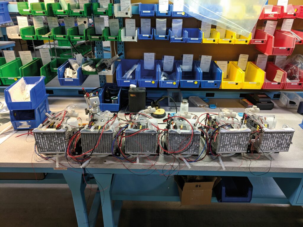
“We supply volumes of tens to maybe 100 fuel cell products per year, and if we go up to thousands or tens of thousands then we might well convert to automated stamping of metal plates,” Robinson says.
Notably, the MEAs are not manufactured with gaskets or other sealing components – they would be referred to as ‘seven-layer MEAs’ in this case – nor does Honeywell manufacture its stacks by fitting a gasket between each MEA and BPP. Instead, it uses a sealing method pioneered by Protonex that enables a stack that uses no gaskets.
“For each unit, we stack up all the MEA and BPP layers; then, in a patented one-shot automated sealing method, all the ‘gaskets’ are formed in situ, around the stack, keeping its internal channels and its exterior sealed,” Robinson explains.
“That is critical to allowing us to mass-produce these stacks at a fraction of the cost of the conventional approach, because we remove the labour cost of including physical gaskets in the stack-up process.
“If you think about a gasket between two surfaces, the only way it works is if the surfaces are precisely flat and tensioned – too much and it flattens out and leaks, too little and you get gaps, and it leaks. Most stack producers therefore resort to very heavy tensioning hardware such as titanium through-bolts to keep sufficient pressure for sealing. Since we don’t use gaskets in our assembly, we don’t have to worry about tensioning, which is what enables us to make a liquid-cooled stack that’s so lightweight and small.”
Thermal management
As mentioned, the 600U and 1200U are closed-cathode, liquid-cooled systems. “As the US military needs to have reliable power from mountain to desert, they were never interested in having us develop air-cooled systems that are sensitive to environmental conditions,” Robinson says.
Although the standard-issue coolant is water, the company can alter its coolant according to the expected operating environment. In its tests at sub-zero temperatures for example, it has used water-glycol as well as water-methanol mixes.
“At higher temperatures, the limitation comes from the fuel cell stack’s internal environment being run at 60 ºC,” Robinson adds. “The closer the ambient temperature gets to 60 ºC, the larger the heat exchanger needs to be – the heat exchanger’s size correlates proportionally with the ΔT.
“For most UAVs, a 45 ºC maximum ambient temperature enables an appropriately small heat exchanger that’s easy to integrate, and which is not problematic to design into your aircraft. We’ve run special tests and applications with the DoD where we had to run hotter than that, and in those cases we went with a bigger heat changer to keep the stack’s heat from rising above 60 ºC.
“To be honest, we’ve generally found that for almost every aircraft we integrate on, we make a custom heat exchanger. We work with a number of heat exchanger companies that can customise their components quickly and affordably, and we can’t pass that up if it means the customer gets to minimise or even not need any changes to their airframe to accommodate the heat exchanger.”
The stock heat exchanger is typically square-shaped, measuring around 10 cm2. Most customisations stem not only from the aircraft’s shape but from the airflow rate, and integration is typically carried out in one of two ways. In fixed-wing UAVs it will probably sit inside the fuselage and receive airflow via a duct, whereas in multi-rotor aircraft there will be a pair of them, one each under an opposing rotor arm for balance, with direct cooling coming from the propellers.
“As liquid is pumped through the fuel cell, we have a proportional valve system that can route more and more coolant through the heat exchanger as the temperature shows signs of rising,” Robinson says.
“Obviously, the further you place the heat exchanger from the fuel cell, the more tubing weight you carry, and the harder the pump needs to work, but we tend to work closely with customers on optimising their hydrogen powertrains for both weight and thermal efficiency.”
Future plans
Although the move from Ballard to Honeywell was motivated primarily to best serve its DoD customer, interest in Robinson’s team’s fuel cell designs (and the range of partners it therefore works with) continues to widen. Robinson says, “We’ve recently started field trials with a couple of interesting companies and their platforms, which we can’t name at the moment.
“One is a VTOL-transitioning aircraft, which is ideal for fuel cells as you can size the battery to the take-off and landing, and size the fuel cell for the cruise phase, getting the best of both worlds. The other is a UGV, specifically a quadrupedal robot, which is a commercial as well as a DoD platform. It’s a vehicle type we’ve not worked with before, which is quite exciting for us.”
Protonex company history, from Ballard to Honeywell
Protonex spent the early 2000s developing numerous small fuel cell technologies to enable reliable electric power for the US Department of Defense (DoD) in extreme environments. UAVs emerged as the most viable application of these technologies, and in 2015 Protonex was acquired by Ballard, but Protonex saw applications in larger-scale urban air taxis and even crewed aircraft as a potentially critical direction to move towards. Their development was driven strongly by the DoD, as well as some civil and commercial organisations.
“Honeywell was one of our partners and customers that we were working with on hydrogen-powered UAV solutions, and Ballard’s long-term strategy did not include the US DoD or the aviation market,” recalls Phil Robinson, senior director of engineering for zero-emissions aviation at Honeywell Aerospace.
“It was therefore decided that the business originally started at Protonex would be better placed at Honeywell, not Ballard,” he says. “Honeywell has long been closely aligned with the aviation world and has had a lot of success with DoD programmes, so it acquired the UAV business in 2020.
“The big advantage for us since then has been Honeywell’s expertise in what it takes to build, and most of all certify, aircraft-grade equipment. Commercial users increasingly want to fly BVLOS, and there’s going to be a wave in the near future of uncrewed aircraft well over 25 kg carrying Lidar, multi-sensor gimbals and cargo deliveries. So, knowledge of how to engineer and manufacture subsystems in a way to ensure they can be certified by the FAA and similar organisations is really critical.”
Specifications
600U
Dimensions: 24.1 x 17 x 14 cm
Weight: 1.8 kg
Maximum continuous power output: 600 W
Voltage: 12-33.6 V
Maximum continuous current: 30 A
Peak current: 50 A
Specific fuel consumption:
53 g/kWh at 200 W
63 g/kWh at 650 W
600U-HV
Dimensions: 23.1 x 15.5 x 13.7 cm
Weight: 1.9 kg
Maximum continuous power output: 600 W
Voltage: 12-33.6 V
Maximum continuous current: 60 A
Peak current: 50 A
Specific fuel consumption:
53 g/kWh at 200 W
63 g/kWh at 650 W
1200U
Dimensions: 43.2 x 26.67 x 16.5 cm
Weight: 4 kg
Maximum continuous power output: 1200 W
Voltage: 18-84 V
Maximum continuous current: 60 A
Peak current: 100 A
Specific fuel consumption:
53 g/kWh at 400 W
63 g/kWh at 1300 W
UPCOMING EVENTS


