


Cable harnesses
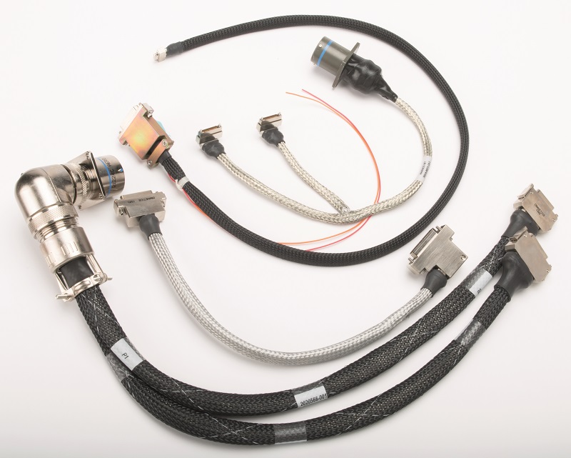
Harness designs depend on the material and engineering requirements of the wiring in them, writes Rory Jackson
In many ways, cable harnesses are a microcosm of the autonomous vehicle world. As uncrewed systems become bigger, more complex and with more and more electronics and functions, so harnesses are becoming larger, more complex and more diverse in their constituent parts.
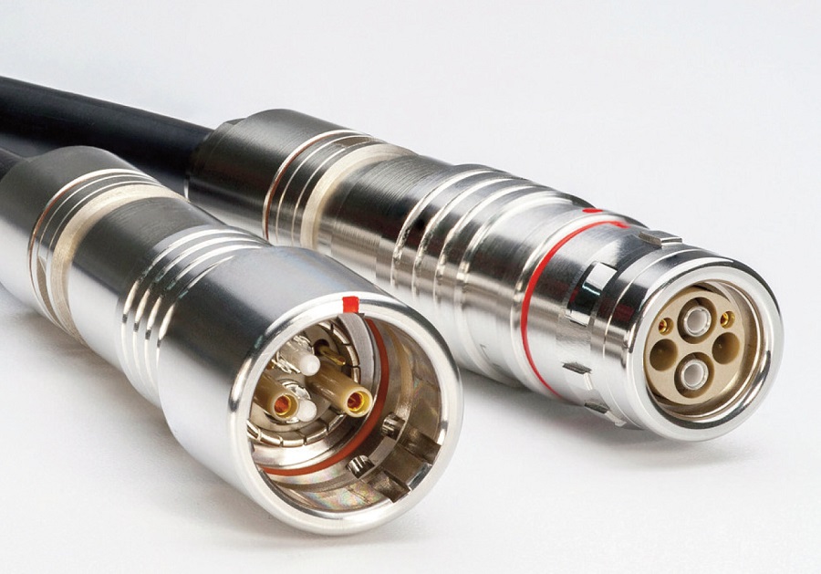
It therefore pays to pack as much power and data capability into each harness as possible. Our past features on connectors (issue 12, February/March 2017; issue 24, February/March 2019; and issue 44, June/July 2022) have shown the growing popularity of ‘hybrid’ arrangements that achieve this very purpose.
This carries through to how harnesses are being designed and produced these days, using combinations of different wiring gauges and materials. At the same time though, demand for such products is at odds with mounting EMI issues and heat build-ups inside vehicle bodies, owing to a greater number of subsystems and the cables connecting them being squeezed inside the hull sections for a range of functions, and for compliance with regulations on transponders, GNSS, data links and other RF-centric componentry.
The right harness for the job
Vehicle OEMs need to work closely with cable harness manufacturers to establish the key requirements and constraints of a harness. Critical parameters such as lengths, voltages, local temperature ranges, flexibility requirements, strength requirements, and the systems to be connected at either end should be determined in-house and presented to the harness maker, as more information will naturally mean a more optimised product.
For instance, a cable designed for running into a gimbal could consist of a silicone rubber jacket for high flexibility, and the wiring inside could have extremely high stranding.
Rather than using something like a conventional 7 or 19-strand copper wire, the high-density data outputs and high-speed and fidelity control inputs typical of modern UAV gimbals could mean using wire in excess of 40 very fine strands. The more strands in the wire , the higher its flexibility, life expectancy (particularly against scratches and nicks), and heat dissipation.
On top of that, speciality wires such as tinsel wire are available that can provide very high flexibility but at the cost of low current throughput.
Also, safety-critical niche requirements must be addressed early on. Some vehicle OEMs require harnesses and other components to be made without magnetic materials if, say, a magnetometer or similarly sensitive instrument is nearby and the vehicle designer wants to avoid sources of interference. In that case, connectors with nickel plating for instance would be off limits, as would any shielding or braiding.
Some customers choose to approach cable harness manufacturers with source control drawings, which will typically define the range of tests they need across conductivity, vibration and so on. From reviewing that information, a cable harness maker can produce a list of what does and does not need to be discussed further to pin down material and engineering requirements, as well as potential substitutes, as those discussions progressively unearth which wire types, manufacturing approaches, or jacket materials for instance are unacceptable for the use case.
Once the ideal components and parameters of the harness are defined, the cable producer can start modelling the ideal harness in CAD (not with FEA, as there are too many variables to accurately simulate lifespan or performance), to produce a drawing that the customer can check and send back with requests for iteration or sign-off. Manufacturing can then begin.
Manufacturing and QC
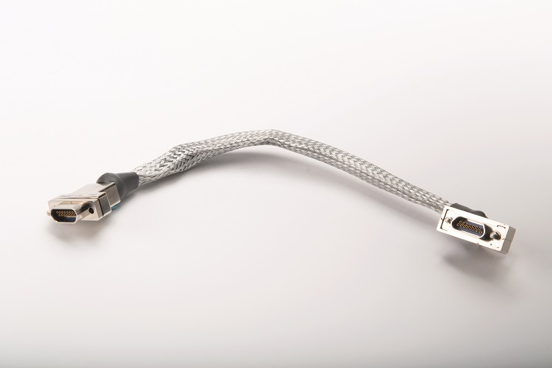
Production of a cable harness typically begins with cutting multiple single wires to the desired length, after which the ends of the wires are stripped of their protective coatings so that the exposed copper (or other core material) can be attached to connector pins.
The wires are then bound or twisted together depending on the end-user’s preferences. Twisted pairs or higher quantities of wire being weaved together is desirable from an EMC standpoint as it reduces EM radiation from the weave and increases rejection of external EMI, although it does drive up the cost of cable harnesses owing to the labour-intensive nature of the weaving process.
Naturally, twisted or weaved wires are increasingly popular in the uncrewed world given the higher quantities of embedded computers, modems, sensors and other electronics and sources of EMI inside vehicle hulls.
After that, the wire assembly can be fitted into its protective jacket, which can encompass various materials and layers depending on the application and integration case. Aluminium shielding for instance can provide further EMI absorption, and a wide range of plastics are available for different temperature, chemical and physical hazards.
After these main jackets, other components such as abrasion-resistant sleeves can be fitted over key sections of the harness to counter potential threats to its integrity in the vehicle. Lastly, the exposed conductor is attached – by crimping or soldering – to its connector, each wire and its pin corresponding to a function for the harness.
Adhesive and other bonding options are available for securing outer cable jackets to connector shells, with stronger adhesives used in cases such as military uncrewed systems, where technicians in a rush could grasp and pull cables with more strength and at angles than are not ideal for safe de-mating, creating a risk of wrenching cable and connector apart.
Most of these steps in the manufacturing process are still carried out manually. Procedures such as weaving, or inserting and routing wires through sleeves, are cumbersome for a machine to execute.
Also, the inputs and conditions they are subject to, such as variances between batches of materials or humidity or heat during shipping, will induce minute differences between wires, plastics and other materials that could interfere with the precision a machine would need to produce cable harnesses repeatably. Automation therefore still has many limitations in terms of cable harness production.
There are some exceptions to this though. Braiding looms for instance can achieve fast and uniform weaves of protective jacketing material about a set of fastened cables in an automated or semi-automated way. They typically wrap their materials much tighter than human workers can, which leads to the harness being stiffer than manual workers could make it, and which can make routing and integration more challenging.
However, that tightness also makes it harder for EMI, heat or anything else to penetrate or escape from the wires. A slip-on braid by contrast could be looser owing to the flexing that often occurs while workers pull or push it over wires.
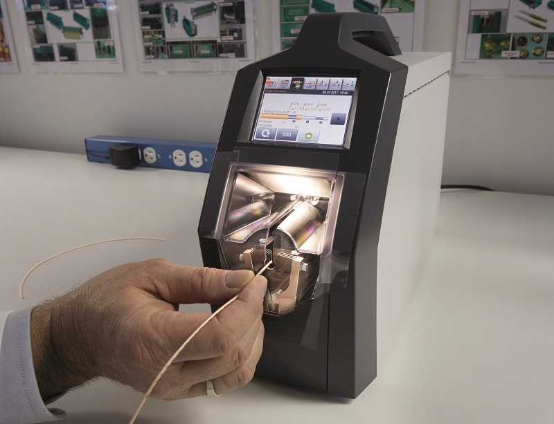
Also, automated machinery is available that can perform consistent and repeatable stripping of sets of wires that are controlled for their cross-sectional diameters, and semi-automated stripping devices will function by performing the cut when it detects that a person has inserted a wire into its aperture.
Lastly, semi-automated crimping systems can terminate wires to contacts in a repeatable and less labour-intensive way than conventional hand-crimp tools. These are often pneumatic systems, using pressurised air to drive down the crimping tool to compress an exposed wire conductor (inserted into the tool by a human worker) against the contact terminal.
The efficacy of these machines can drop as wires and contacts get smaller though, as it becomes challenging to position wire and contact together for the machine to work.
Performing the termination by hand might seem more onerous, but for twisted pairs it is vital, as the pair must first be slightly untwisted, so that the wire can be stripped at the correct length, the conductor can be crimped or soldered onto the contact, and finally the crimped cable can be re-twisted back to the form it started with.
Crimping is generally agreed to be more easily performed, more repeatable, easier to train and check for, and safer than soldering, although soldering can be preferred in certain use cases, with some power wires measuring around 10-
14 AWG being designed for soldering only. Also, one advantage of soldering is that crimp tools are more expensive, but most applications nonetheless recommend crimping, with some companies estimating that 75-80% of their cable assemblies are crimped.
Either way, that process must be handled carefully, particularly for twisted pairs so that the twist is maintained as the wire terminates at the connector. Any disruption in the twist that makes its way into the final product will lower the impedance and EM performance of the connection.
As a final, optional manufacturing step, some suppliers will perform back-potting, for greater stability and protection for the cable assembly against ingress of water and dust through the back of the connector shell. This typically involves applying resin, a curing phase, then a visual inspection.
Testing
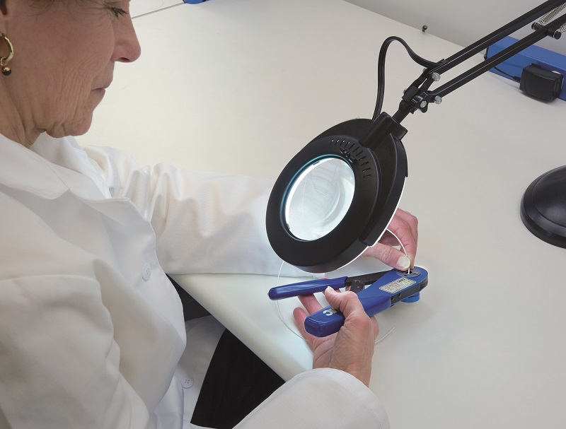
Quality control systems in manufacturing typically ensure consistency in physical and performance characteristics between units and batches of harnesses, with both human inspectors and automated vision systems scanning cables coming off production lines such that tests are limited to initial units of a new design, or to one-off sample tests to gauge the viability of a batch in production.
Certification and homologation requirements typically define the type and extent of testing cable harnesses. These can include electrical tests in which they are cycled through different voltages and currents, to observe how they behave and last over extended use and misuse, or what resistance characteristics they exhibit, which becomes increasingly important with longer cable lengths.
Also, flexibility tests will put a physical strain on cable assemblies to replicate those that the design will experience during repeated routing, mating and un-mating. Particular attention is paid to the joint between cable and connector interface, as that is assumed to be the part most likely to break first.
Beyond that, more specialised tests for high-end requirements include flame testing, water testing, drop testing, strength testing and many other ways of investigating the suitability of a harness to its environment.
While this list can become a long one, much of the testing can be automated, with a lot of it being carried out inside programmable machinery to ensure the repeatability of test results. Reports on these tests can be sent to customers and their technicians to show the limits of what their products can endure.
Jacket materials
There are many outer jacket materials, thicknesses and structures available, with the best choice depending strongly on the environment in which the harness will operate. Understanding local properties such as temperature ranges, what chemicals it will be exposed to and their physical state, or the likelihood of icing or outgassing at altitude are key. It is increasingly common for instance that harnesses in high-end applications need to survive in temperatures from -55 to +175 oC.
Also, military integrators increasingly want specific properties, such as requiring that the jacket’s chemistry be smoke-free or sometimes halogen-free; the latter is also being requested by civil and commercial organisations. Despite their excellent flame and heat-resistance properties as additives in a cable harness jacket, halogens are harmful to human health.
Technicians can avoid their negative effects by using PPE, but this move by the industry towards halogen-free materials could lead to a growing use of jackets made from plastics such as silicone rubbers, polyurethanes, polyethylenes, polyamides, polypropylenes, thermoplastic elastomers or ethylene propylene diene rubbers.
That said, materials such as ETFE (ethylene tetrafluoroethylene), PTFE (polytetrafluoroethylene), PFA (perfluoroalkoxy alkanes) and FEP (fluorinated ethylene propylene) are popular across a range of heavy-duty applications and jacket types.
Among these, heat shrink tubing is increasingly used, as such materials contract radially when heated. That means wires can be fed through them in their comparatively spacious normal state, and then the subsequent heating enables the jacket to tighten and the overall harness to take up less space.
PTFE tubing exhibits low friction, strong resistance to puncturing and chemical damage, and can operate in temperatures from -55 to 175 oC. FEP is less expensive than PTFE, and lacks some of its temperature and mechanical properties, but it is more flexible and easier to manufacture.
That trade-off tends to happen with other materials as well. ETFE for instance can exhibit up to 33% higher tensile strength than PTFE, but the latter is again more flexible: it will stretch 66% more than ETFE before breaking. PTFE also retains the advantage in friction, with one-third of ETFE’s coefficient of friction, meaning reduced wear in tight spaces where many enclosures or other cable harnesses might be tightly fitted, and where movement might be induced by vibration or g-forces.
Polyurethanes and silicones on the other hand are widely used in harnesses for those seeking simpler, less expensive and halogen-free materials in light-duty applications. While both materials come in many forms, silicones mostly have better thermal and UV resistances, while polyurethanes have the advantage in terms of abrasion resistance and tensile strength.
On top of these various, well-established materials, some unconventional jacket choices are gaining in popularity, such as cross-linked polymers, which are being adopted more in engine and battery compartments for their heat resistance properties. They also exhibit significant low-temperature toughness, abrasion resistance and radiation resistance, while also having lower hardness and rigidity than conventional polymers (enabling greater flexibility).
The exact process of cross-linking refers to creating bonds between polymer chains within the material, and can take the form of different chemical reactions, including the use of electron beams, peroxide and silanes.
More unusual options have included heat shrink tubing material with silver embedded in it. While the material remains non-conductive, it integrates a degree of EMI protection directly into the jacket material without necessarily using a conventional shielding component.
Shielding
Materials and components used for shielding in modern cable harnesses continue to consist largely of aluminium foils and braids. Modern approaches to shielding include a growing popularity of combining a braid and a foil across the length of a harness (the former providing 85% EMI protection, the latter 100%).
The total quantity and hence cost of aluminium shielding can be minimised by using shielded twisted pairs (STPs), which are an increasingly popular harness design for dedicated high-speed comms or LAN connections. In these applications, power and low-speed comms are not combined within the harness, and can reduce the overall use of shielding by limiting the use of aluminium shields to those comms-heavy cables that need them most to prevent signal interference.
A typical STP cable harness contains multiple twisted pairs, each pair having its own individual shielding to minimise interference between them. The term has also however been used to describe cables with multiple twisted pairs, each individually unshielded but with a single foil or braid shielding encompassing all of them, concentrically and just inside the final protective outer jacket.
Beyond this are many terms for the various combinations of shielding approaches to high-speed twisted pair cabling. S/UTP (shielded/unshielded twisted pair) for instance can be used to describe designs in which the twisted pairs are shielded collectively but not individually. When they are shielded individually with foil, they are often called foil twisted pairs (FTPs), although FTP foils are light and therefore prone to tearing during integration and routing if tugged or bent excessively.
Conversely, S/FTPs (shielded/foil twisted pairs) specifically describe those instances where twisted pairs are shielded individually and collectively. Foil is applied at the individual level, and a thick braided shield around the outside makes the cable more resilient to bending or pulling damage during installation.
There are many other permutations, such as F/UTP, when a foil is used collectively with no individual EM protection, or SF/UTP where both foil and braid are applied at the outer level about the individually unshielded twisted pairs.
Cable management
When routing cables throughout avionics bays or other vehicle sections, it is common to use a wide range of external components such as cable tie straps, slotted panels, P-clamps or T-clamps that can be fastened to walls, brackets or bulkheads.
These can therefore bond a cable assembly to an airframe or chassis, and keep cables from becoming a disorganised mess with the risk of one cable tugging on another, or hazardous levels of friction occurring between them.
These sorts of external fixtures are well-understood and widely available. Gaining popularity however is a range of internally fixtured cable-tie mounts. One new example of these is a type of injection-moulded part produced in Ultem 2400, PEEK and other plastics.
As these feature an internal fixture, it replaces the external fixtures used with many cable management products, saving technicians from having to remove the external fixtures when reorganising cables and cable ties. That design aspect makes integration easier, as well as passively applying 20-35 kPA of pressure to the area being bonded.
Future of harnesses
As discussed, there are a wide range of approaches cable suppliers will take with the various plastics and coppers making up their cable assemblies, and in future these are likely to incorporate an array of technologies such as additive printing for bespoke connectors and cable management solutions.
New materials such as foamed plastics are also likely to emerge, which can hugely reduce the weight of cable assemblies across vehicles.
However, the biggest shift in cable technology to come within the next decade might stem from manufacturers increasingly developing and offering fibre optic cable assemblies to uncrewed vehicle manufacturers.
The high-speed data rates and bandwidth advantages of fibre over copper are well-understood – optical cable transmissions are theoretically only 31% slower than light itself, and could have over 1000 times the bandwidth of an equivalent size of copper cable. On top of that, optical fibre is effectively immune to noise interference, as its laser signals are not disrupted by EM emissions, and it does not emit EMI either.
That closed architecture is useful for defence operators and anyone else concerned about data security. So long as decent encryption modules are used in the network, it becomes nigh-on impossible for hostile parties to log what is being communicated across a fibre network, unlike in a copper one.
Now, with autonomous vehicle OEMs and fibre cable manufacturers both targeting 100 Gbit/s comms capacities, the former increasingly discusses potential supply capabilities with the latter. Also, the cost of fibre – which in the past was prohibitively high compared with copper – is falling. Although it was around twice the price of copper just a few years ago, their prices have grown much closer thanks to higher manufacturing volumes and r&d into production methods.
The growing use of fibre is in turn spurring more interest in active cabling. These are copper-based harnesses for data links that contain integrated circuits in their connectors for mitigating or compensating for attenuation, cross-talk and other problems affecting data fidelity, speed and bandwidth in otherwise ‘passive’ cables, hence improving the overall performance of the harness.
Through the signal and fidelity-boosting nature of their ICs, active cables can use much less copper than passive cabling for a given set of performance parameters, so potentially they can be far lighter. They can also be made more than twice as long as passive cables with the same end-to-end performance.
The drawbacks of active cabling revolve around the greater complexity of designing and manufacturing them, owing to their ICs and the fact that they tend to integrate a lot of shielding, which contributes to them costing five to 10 times as much as passive cables.
But just as demand has pushed down the price of fibre cables in recent years, so the rise of connected and autonomous vehicles might well drive a boom in these and other forms of harnesses to come.
Acknowledgements
The author would like to thank Scott Unzen and Travis Neumann at Omnetics, Steven Lassen at Lemo, Jeff Lewison at Northwire, Giorgio Potenza at Harwin, Dax Ward at St Cross Electronics, and Moises Valle at Click Bond for their help in researching this article.
UPCOMING EVENTS


