


H3X HPDG-30 hybrid

(All images: H3X)
Beating the battery
Rory Jackson unpacks how this company took on some of the biggest challenges to efficient UAV power and succeeded, creating this turnkey hybrid powertrain along the way
The company H3X is an aerospace-focused e-powertrain developer and manufacturer, which was founded in 2020 primarily out of a desire to take on a challenge set (unofficially) by the US’s Advanced Research Projects Agency-Energy (ARPA-E) in 2019.
While much of the discussion around decarbonising aviation has focused on making battery packs more energy-dense, breakthrough advancements in lighter, more energy-dense batteries are rare and their successful productionisation is rarer still. Hence, when ARPA-E looked instead into how making e-powertrains (from the motor to the inverter, gearboxes and all related housings) lighter might be a more feasible approach, it determined that an e-powertrain capable of 12 kW/kg would indeed enable all-electric flights of 150–200-passenger commercial aircraft (akin to the Boeing 737) on modern batteries and hydrogen fuel cells.
Although it also determined such power density was “beyond the capability of state-of-the-art technologies” (with e-powertrains of the time capable of little more than 3 kW/kg at best), H3X took matters into its own hands, subsequently engineering and supplying products capable of over 10 kW/kg.
As Jason Sylvestre, CEO and founder of H3X recounts: “We went through Silicon Valley’s Y-Combinator accelerator in 2021, and shortly raised a seed round after that, using it to develop the core tech by which we’re achieving very high efficiencies and power-densities.
“We developed a range of solutions, including a 250 kW e-motor, which was then sunset by a 180 kW system, but then a DoD customer complained of a gap in the sub-50 kW power class. So, in four months in 2023, we went from a concept to a shippable prototype for our 30 kW HPDM-30 motor drive, which is a key enabler of our new HPDG-30; our first hybrid powertrain developed specifically for UAV integrations.”
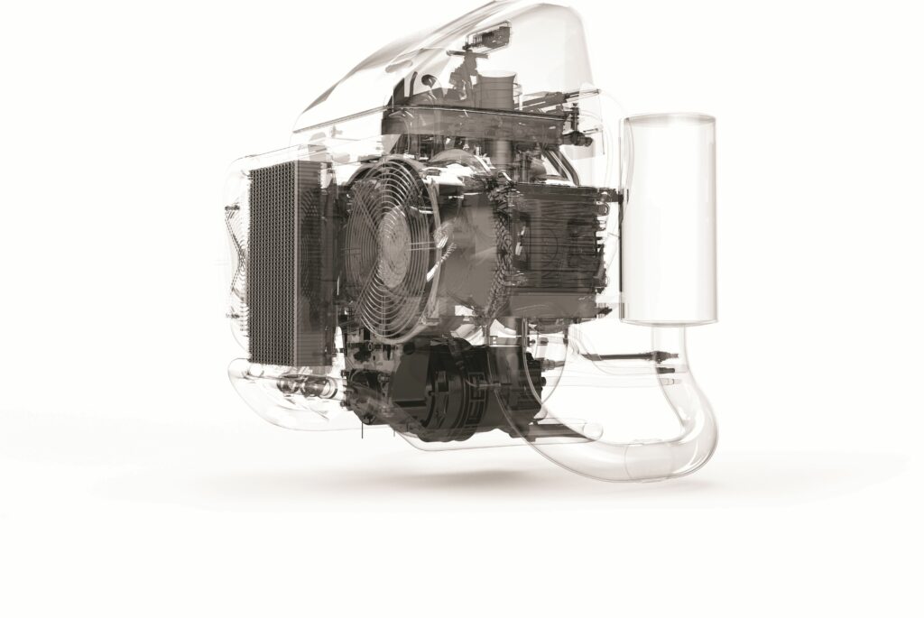
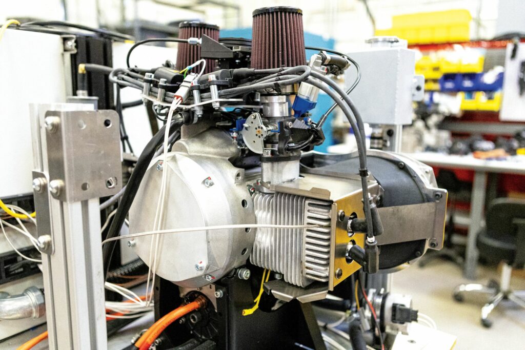
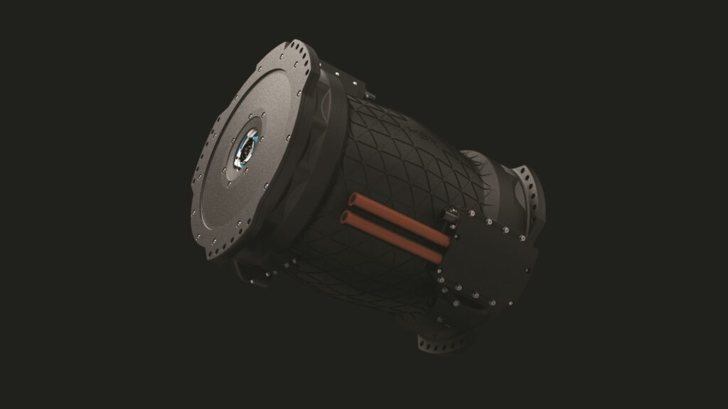
The HPDG-30 broadly comprises H3X’s electric propulsion systems integrated around a naturally aspirated, two-stroke, spark-ignited boxer from Hirth, resulting in a 32 kg, 30 kW (180–450 V DC) hybrid unit, with a 650 g/kWh specific fuel consumption (SFC), a combined air- and liquid-cooling architecture and an anticipated time between overhauls (TBO) of 500–1000 hrs.
This new hybrid system was similarly solicited by the US DoD in 2025, who sought new, efficient UAV power plants. Fortuitously, H3X had been working on some turbogenerator prototypes since 2024, and although these exhibited high power density, they also suffered poor SFC and TBOs.
“So, we looked into some Wankel rotaries and two-stroke reciprocating engines, eventually coming across the Hirth F23, which paired brilliantly with the HPDM-30 from a power density perspective, and brought Hirth’s great track record on reliability with it,” comments Blake Bremer, senior mechanical engineer at H3X.
“We did some studies and calculated that if we could hit a 1 kW/kg power density, or around 30 kW continuous output for a roughly 30 kg total hybrid powertrain mass, that would outcompete lithium-ion batteries and most turbogenerators on the market.”
Knowing its tech was more than capable of achieving such targets, H3X adopted a go-fast prototyping approach, testing and iterating to see what would (or wouldn’t) work, starting in May 2025 and bench testing proof-of-concept builds from July that year.
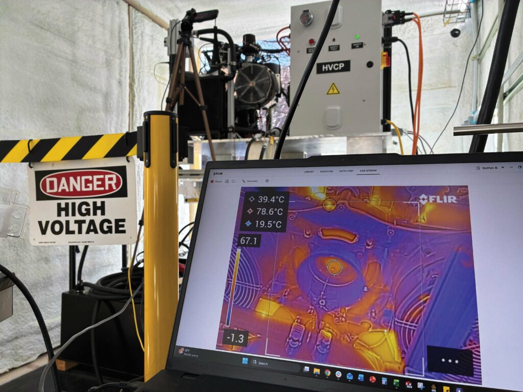
Following some hardware refinements in December 2025, the first prototype was shipped to a beta customer in January 2026, and as of writing the system has been tested with just over 65 hrs at maximum continuous power output across two test units, with 500 hrs due to be reached by close of 2026. Cold-starts down to 0 C, density altitude operations up to
9000 ft (2743.2 m) and effective thermal management at maximum power output up to 35 C ambient have also been validated.

“We have a three-generation release strategy: Gen1 was purely a bench top integrator for customers’ iron bird testing, to plan system integrations, battery sizing, CAN interfaces and those sorts of things,” Bremer continues.
“Gen2 is set for availability in Q3 2026. That’ll carry over Gen1’s hardware, COTS components and design intent into a flight-testable format. And Gen3 will be a fully optimised genset, offered in customisable, turnkey packages in which the HPDM-30 makes at most 15% of the all-up weight – with batch production of that to start in the first half of 2027.”
System integration
The internal combustion engine core of the HPDG-30 is the Hirth F2302, which has been manufactured in available volumes for decades, and thus has a lengthy, proven service record, including bulletins and updates, contributing to its reliability. Although H3X had experimented with several other engines at lower levels of technical readiness during its early DoD work, they showed myriad issues that the Colorado-based firm was keen to avoid running into again.
“So, that maturity is really appealing for a new product, where we want to de-risk certain aspects while easing R&D needs. Plus, its peak output of around 35 kW matching with the HPDM-30’s of 33 kW, meant neither was over- or undersized at all compared with the other,” Bremer says.
“Hirth was also very open to working with us; they’ve been an excellent partner, with really good engineering and customer support teams. They’ve helped us overcome any issues or obstacles really quickly and efficiently.”
As of writing, the COTS 2302 has not been modified at all, but the Gen3 will undergo some mass optimisations, such as the removal of redundant systems like the 12 V starter motor and the 500 W, 12 V generator, which Hirth packages as standard with the 521 cc engine.
The HPDM-30 comprises both a permanent magnet synchronous motor (PMSM), a three-phase inverter and a control system. It is mechanically coupled to the 2302 via a belt drive with a 3:1 reduction ratio, enabling both machines to run in their optimal speed bands – the engine from 4900–6500 rpm and the motor drive at 15,000–20,000 rpm.
“Using a belt is far lighter than an equivalent planetary gear system, and it’s very low maintenance – there are no oil changes or rotating lip seals,” Bremer adds. “And we’ve chosen a belt product that has a long, proven track record operating in similar systems and environments, so we’re very confident in how it performs.”
As the 2302 is an air-cooled engine, intended to have its heat (particularly at its cylinder heads) dissipated by propeller downwash, or by free air from the forward motion of a fixed-wing aircraft, the HPDG-30 adds two electric fans for forced-air cooling. The system can thus function safely on multi-rotors or VTOL-transitioning fixed-wing aircraft that may hover or otherwise sit relatively motionless for extended periods.
“We also have a liquid cooling loop integral to the HPDM-30, to which we also add a pump, a radiator and a radiator fan, and then we also integrate an auxiliary electronics module, which does power regulation for the subsystem lower bus voltages and some of the CAN bus comms for control from the host aircraft, while also reading all the temperature sensors that we integrate,” Bremer continues. “In short, Hirth provides the engine, exhaust, fuel pump and ECU, while H3X adds everything else.”
Mounting provisions and exhaust routings are freely customised per end-user needs, with flying leads provided for DC connections and fluid connectors present for fuel lines.
The motor-generator
Considerable weight in our investigation must be given to the HPDM-30, owing to its role as the electromagnetic means by which the 2302’s mechanical horsepower is converted into high-voltage direct current.
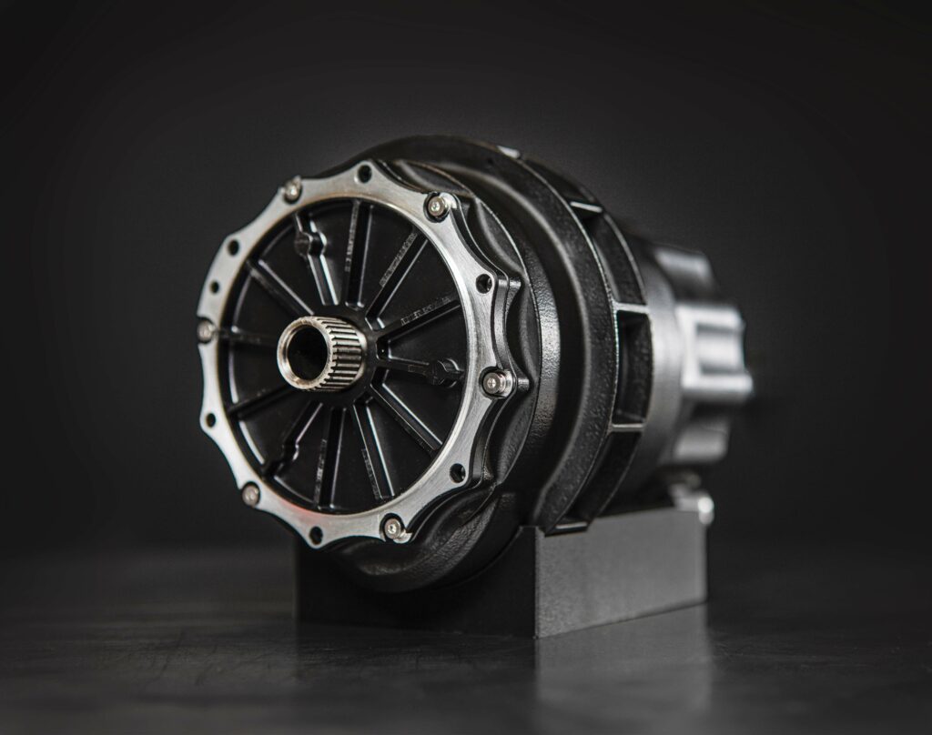
The HPDM-30 is an integrated motor drive, which means that it combines both the electric motor and the inverter into a single housing, enabling them to share an active liquid-cooling system, designed and patented by H3X for optimising the powertrain’s efficiency with respect to weight, power and heat.
“The liquid cooling is something we’re happy to explain a lot about because it’s really necessary for reaching the power densities we’re capable of. Being able to efficiently pull waste heat out of the motor lets us shrink many components without sacrificing power output or throughput,” Bremer says.
“We have looked into making a new design for a future air-cooled version of that motor, with the aim being to reach the same power levels while also reducing the weight of the thermal management system.”
The electric motor itself is a high-speed radial flux machine, spinning at 20,000 rpm in typical operations (hence the belt), featuring an interior permanent magnet (IPM) rotor design, as well as a stator, which comprises many of the innovations key to the high power density in H3X’s powertrain. Most importantly, those include a winding insulation system configured for very high thermal conductivity, as well as a stator structure consisting of electric steel laminations exhaustively selected and manufactured using proprietary means (with both of these technologies discussed below).
Control of the motor-generator and rectification of its AC power into DC comes by a three-phase, silicon carbide (SiC) inverter. In addition to the thermal management benefits already given above, housing the motor and inverter together means running little-to-no cable lengths between the two, preventing risks such as overvoltages, excess EMI and damage to windings or bearings that could result from excessive lengths of three-phase cabling.
“It’s just a lot easier to contain EMI – specifically, common mode EMI – and tightly filter it when we house the motor and the inverter together,” Sylvestre says.
The HPDM-30’s housing is predominantly an additively manufactured (AM) system. That process is vital to achieving the helical geometries of the liquid cooling loops that run adjacent to the heat-generating stator teeth and inverter power electronics. The exact channel geometry is patented, and enables H3X to print the motor drive jacket while forgoing the use of support material (and thus skipping the challenge of washing or removing such material from the printed parts afterwards).
“Once printed, we take each housing and post-machine all critical surfaces, as you still get a very rough finish even with very good quality AM parts,” Sylvestre notes.
“So, for example, really important mating surfaces like the stator or the inverter cavity, we use standard CNC equipment to give them a smooth finish that’s better for mechanical integration and thermal interfacing. In fact, both the stator’s and the rotor’s lamination stacks are made here, in-house. Our past suppliers for those just weren’t hitting the tolerances and stacking factors we needed, so we’ve made our own tooling, fixtures and processes to produce stacks with very tight tolerances and about a 98% stacking factor – or a 96% electromagnetic stacking factor when accounting for layers of insulation coating on the laminations.”
The final inverter integration and assembly is also performed in-house, the company opting to vertically integrate wherever sensible, if doing so stands to pose a benefit in terms of performance, quality or lead times.
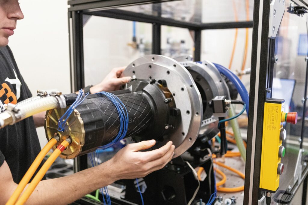
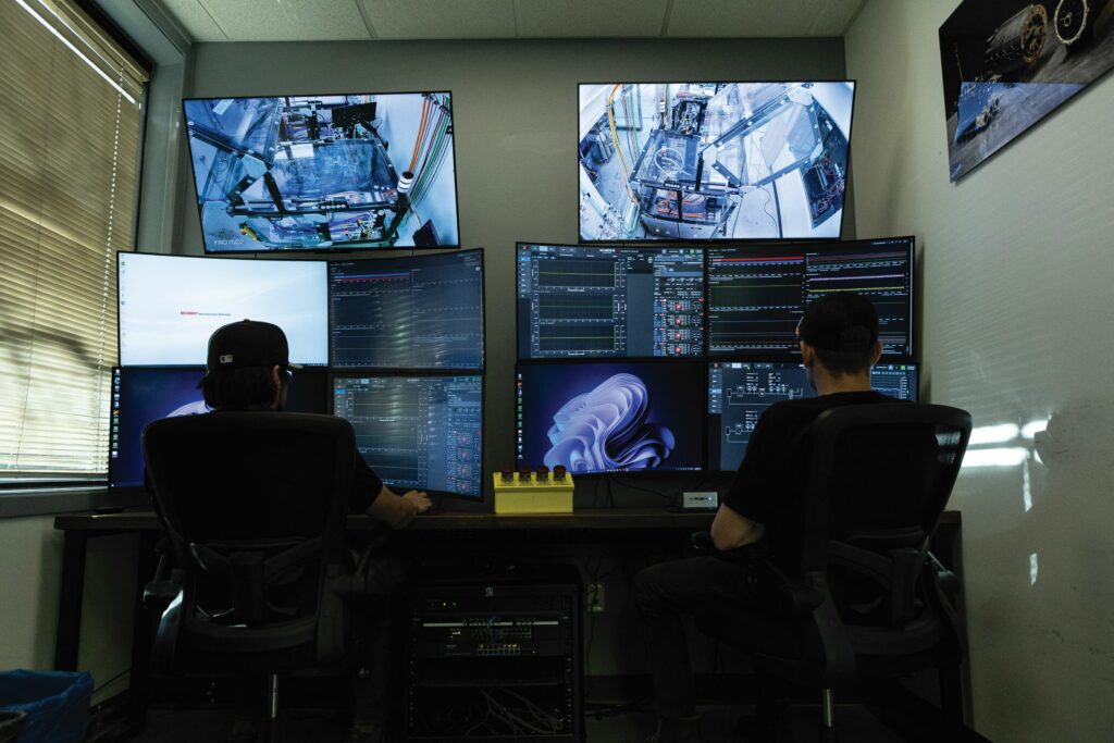
To that effect, H3X has also designed and constructed four proprietary dynamometer test stands in its Colorado facility – with a fifth under construction as of writing. Its IP there includes all electrical and software systems underpinning the dynamometers; for example, data processing, data visualisation and data accessibility infrastructure.

“We’ve set up a platform by which any engineer in the company can view live or historical dyno data from any computer’s browser; that’s really important, because we really want to remove any friction that engineers would typically have in viewing data from any test,” Sylvestre adds.
“It’s crucial to be able to rapidly make decisions or give feedback relevant to our design processes, to make that iteration loop between design, build, test and redesign phases run as quickly as possible. A lot of our engineers previously worked at Tesla, and being given a blank canvas to design their dream testing and data platform is something that makes them really excited.”
The software platform is also key to automating the testing processes, enabling greater efficiency and quality of life for the H3X engineers’ workflows. Moreover, designing their own test stands enabled the team to agree on a dynamometer configuration flexible enough to support testing of all of H3X’s different motor designs, as well as one compact enough to fit two stands per cell and robust enough to run 24/7. Those qualities thereby unlock high rates of testing throughput in both R&D testing and automated production testing.
IPM rotor
As mentioned, the motor’s permanent magnets are mounted inside the rotor, the IPM design being highly flux-concentrated in comparison with surface permanent magnet (SPM) designs, enabling improvements in the former in both inductance and reluctance torque.
“We’ve seen SPM machines that have 10–20 microhenries [µH] of inductance, and because of that they need an inverter capable of switching frequencies of around 100 kHz to avoid crazy current and torque ripple,” Sylvestre says.
“So having higher inductance is useful for preventing those issues, but IPM also helps in our three-phase short condition. If we’re in a specific fault scenario where a three-phase short is the best course of action, we can basically three-phase-short our motor continuously without overheating it.”
The rotor stacks are made from 0.1 mm sheets of either cobalt or silicon iron laminations (depending on application), along with laminated and segmented permanent magnets and a proprietary adhesive. After the shafts and magnets are inserted and bonded, the rotors are spin-tested in both a room temperature and a 300 C temperature chamber because (unlike the stator) the rotor does not benefit from active cooling and runs far from the cooling jackets. Hence, it must reject its heat through either the air gap or the bearings while potentially running up to 200–250 C.
While COTS adhesives would break down amid such heat, H3X’s has been formulated to avoid doing so, enabling it to support the structure to not burst apart in hotter operations.
That, plus having an IPM configuration to begin with, both help avoid the need for a carbon fibre sleeve wrapping around the rotor, which would inevitably widen the air gap (beyond its 0.25–0.5 mm standard width), and so reduce the flux density able to cross that gap and create electromotive torque, on top of driving up manufacturing costs through being an expensive and complex part to produce at scale (particularly for aerospace regulations).
The magnets meanwhile are samarium cobalt (SmCo) pieces, which provide better performance (particularly in air gap flux density) than more conventional neodymium (Nd) magnets at +180 C temperatures. While also more costly per gram than Nd grades of permanent magnet material, H3X avoids running up large bills of SmCo material by virtue of its high magnet utilisation (the ratio of power or torque against magnet mass), which it derives via its high stator current.
“We’ve also started implementing a new electromagnetics design into some versions of our products, which uses more conventional materials overall than we used to; that results in around a 20% reduction in power density in return for a 70% reduction in cost,” Sylvestre says. “That’s not in the HPDM-30 yet, but it’s on the roadmap.”
The stator
The HPDM-30’s motor features a 12s10p design, meaning 12 slots for the stator windings and 10 magnet poles per rotor. While other PMSM topologies are more commonly used in mobility configurations, such as 12s8p (which could yield a quieter motor with lower vibration), a key advantage of 12s10p is that the stator’s three phases are magnetically decoupled from one another, enabling highly sinusoidal line voltages and currents, and consequently fine motor control with low torque ripple (including in extremely high magnetic saturation conditions).
H3X also notes that e-motors in operation cannot realistically be heard over the noise produced by an engine or propeller, and so even the noise advantages of a 12s8p version of the HPDM-30 would largely be moot.
“Most of all, 12s10p really lets you optimise for power density and efficiency, which are the parameters that aerospace cares about,” Sylvestre muses.
The stator is assembled using a concentrated winding with far shorter end-turns than in more typical full-pitch winding. Together with the 12s10p architecture, the HPDM-30 achieves a winding factor of over 93%, which contributes to the motor’s high torque- and hence current-density.
More crucial, however, is the insulation material used in H3X’s stator windings, which is a proprietary composite material developed in the company’s pursuit of maximising continuous output against rising operating temperatures. The formula was made targeting the highest thermal conductivity possible, to ensure it would transfer heat out from the stator copper and laminations and into H3X’s prized liquid cooling channels with the lowest resistance possible.
By combining various grades of thermally conductive ceramics with electrically insulative polymers, H3X boasts a bulk-winding thermal conductivity of 8.7 W/m-K and a thermally continuous current density ranging between 30 and 45 A/mm2. The company comparatively baselines current state-of-the-art high-performance motors at 1.5 W/m-K and 25 A/mm2.
“When we look at the bulk thermal conductivity of our stator winding, compared with traditional systems, it’s about 480% more thermally conductive,” Sylvestre says.
“Typically, winding insulation is one of the biggest thermal bottlenecks in the motor, and so we’ve put a lot of R&D focus on getting that thermal resistance that runs from the hotspot in the winding to the cooling jacket as low as possible. That’s enabled by innovations in both materials and manufacturing processes.”
While the conventional solution is to use cooling media, either flooding the stator with oil or running water–glycol through in-slot cooling channels, these take up space inside the stator that crowd out those components actually responsible for conducting current and contributing to power generation.
Pumping media at higher flow rates by itself would similarly have little impact because temperature rises observed from stators’ coolants to winding hotspots are often 10–20 times higher than the convective heat transfer from motors’ coolants to their housings or radiators.
However, with H3X’s stator insulation, the liquid cooling system can effectively dissipate the windings’ heat at the jackets, without entering the stator, thereby enabling the windings to

function continuously up to a maximum of 265 C (although operating temperatures of 180–240 C are the norm). An encapsulant also fully encases the stator to prevent partial discharge and thus further extend the windings’ and, hence, the motor’s longevity.
“In the last few years, we’ve particularly focused on improving the manufacturing yield of our insulation composite, reducing waste and fallout from that process, and also on the cost-optimisation side of it, but the core technology has largely stayed the same since our early years, performing just as well and consistently as our choices of copper wire and encapsulant,” Sylvestre says.
SiC inverter
The HPDM-30’s inverter is integrated axially, behind its motor. In the aforementioned prior-generation HPDM-250 solution, the inverter was integrated radially – that is, with PCBAs and housings encircling the perimeter of the motor housing – but H3X has since found through testing to DO-160G (as well as to mil-std requirements) that the axial integration resolved a few key issues with the radial approach.
Specifically, having the inverter components arranged radially exposed them to significant vibrations in operation, and also substantially increased the overall solution’s diameter compared with the much-reduced dimensions of the axially mounted design.
In both cases, H3X has utilised SiC MOSFETs as its preferred type of power transistor, primarily owing to the power efficiency gained by their low switching and conduction losses.
Here, Sylvestre adds: “We pick devices with very low on-state resistance as a result of our design optimisation to minimise the sum of conduction and switching losses. SiC is important for how we can go to very high switching frequencies and so drive down the size of the DC-link capacitor.
“Typically, the DC-link capacitor is one of the largest components in an inverter, and can take up 50–60% of the inverter volume. Increasing switching frequencies reduces our capacitance requirement and, then on top of that, we opt for a special, very high capacitance, high temperature capacitor technology.”
While SiC may have been an indicator of overpriced or overengineered systems five to six years ago, its increasing availability and manufacturing volumes have moved its output rate down the productivity cost curve significantly since then, meaning such devices are no longer as egregiously expensive as they once were.
“But we firmly believe you need to integrate your inverter with your motor if you opt for SiC over more standard silicon IGBTs or FETs because of DO-160G EMI requirements,” Sylvestre continues.

“They’re very stringent, and SiC can be very noisy. If you house your SiC FETs in a separate box and you’re not careful with the design, you can have long phase cables running to the motor and be forced to add a big filter on the output, with potentially a large filter on the input.
“Those filters add weight and they’re lossy, meaning they essentially defeat the main reasons to use SiC in the first place, which are high power density and high efficiency. By integrating the motor and inverter together as a unit, you can really integrate the filtering optimally, and drive down its size and weight.”
The inverter topology makes use of discrete SiC devices distributed across a multi-board architecture, empowering H3X’s team with greater design flexibility to integrate the inverter and motor together than if integrated SiC power modules had been used.
Additionally, the different boards in the HPDM-30 have different functions. Some, for instance, provide control and sensing, while among the others, one will find gate drivers and the DC-link capacitor for the power switching work. The approach is also vital to minimising the overall unit volume, thanks to stacking multiple smaller boards atop each other instead of mounting all components on one large, wide board (which would have greatly exceeded the motor’s diameter).
“It wasn’t easy! Maintaining necessary high-voltage clearance and creepage distances, along with insulation requirements, in such a tightly integrated package took a lot of attention and care,” Bremer notes.
Sylvestre adds: “It was very much a blank-sheet design – we still haven’t seen any historical or reference designs like it. So, there was no external guidance to be gained from automotive or elsewhere.
“We also do all our own firmware and control software in-house, built from scratch on bare metal and C++. And then we use industry standard field-oriented control and space vector modulation, as well as a proprietary self-sensing algorithm that combines high-frequency injection at low speeds with back-EMF tracking at high speeds.
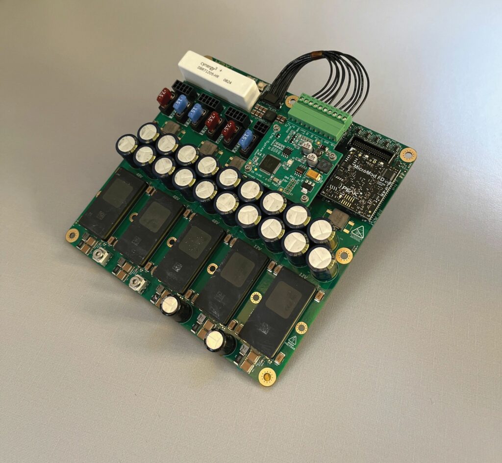
48 V are both provided and many further regulators are available for other power supply levels
“That proprietary algorithm facilitates either primary or redundant rotor position sensing, depending on the application, as well as on-line torque and magnet temperature estimates. It’s maybe also worth noting that we leverage a fault-tolerant, droop control algorithm for our multi-sector machines.”
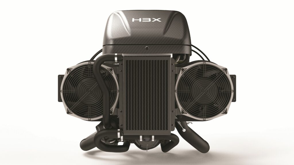
Thermal management systems
Most importantly, integrating the motor and inverter together enables them to share an additively printed structural housing, with what H3X has called ‘synergistic cooling’. This comprises active liquid-cooling, with the coolant channels having been formed inside the walls of the housing during its manufacture via direct metal laser sintering.
That enables the use of common mounting points and cooling channels for the motor and inverter, saving considerable complexity and mass in the overall design, compared with the use of COTS cooling plates. Additionally, the coolant flows through channels that have been designed to run helically in several turns inside the housing radius, inducing useful turbulence, high flow velocity and minimal pressure drop in the liquid, resulting in a high convective heat transfer coefficient.
As mentioned, additive manufacturing is key to producing the complex coolant channel design, given the need to balance the convective heat transfer coefficient against the pressure drop and against the enclosure’s stiffness requirements for minimising vibration.
The water–glycol circulates in a closed loop, into the inverter, then the motor’s cooling jacket, going to a radiator afterwards, and then into a pump for recirculation – the radiator and pump being integrated onto the HPDG-30 platform. During this process, the
HPDM-30 self-tracks its coil temperatures and the peak temperatures of its power electronics, monitoring for whether it stands to exceed key ‘hard’ and ‘soft’ limits that H3X’s embedded software maintain on such temperatures.
Should the soft limits be breached, the control algorithms will derate the power output from the generator in order to keep the powertrain’s electrics and electronics at a healthy operating temperature. If the hard limits are hit, the motor and inverter will shut down because such an occurrence is indicative of something critically wrong in the operating environment or the system itself.
On top of the liquid cooling, as mentioned, the HPDG-30 integrates electric cooling fans for forced dissipation of heat from the engine cylinders and heads, which incurred further thermal management engineering on H3X’s part.
“We do a lot of CFD work in-house for the majority of our products, but for the HPDG-30’s cylinder cooling in particular, we did end up going with somewhat oversized fans, at least to begin with,” Bremer explains.
“That’s been part of our overall strategy of solving problems in the order we want to solve them; targets like trialling and mapping for smaller cooling fans or achieving more optimised airflows will follow in Gen3.”

He adds that the system actively measures cylinder heat temperatures, and so alters the cooling power – that is, fan speeds – relative to those readings, thereby keeping the cylinders in an ideal operating range, while avoiding the risk of overcooling the engine. That also minimises the ancillary power draw and hence losses posed by the fans (which run up to 1 kW at maximum continuous power for both fans combined).
Naturally, H3X’s future roadmap, and particularly with regards to Gen3 includes investigating how best to arrange the liquid cooling system’s radiators with the forced-air cooling system’s fans, such that the latter could also dissipate the former’s heat as well as that of the cylinder heads (along with other plans to consolidate discrete devices into a smaller number of separate units).
As a final thermal measure, the rotor shaft runs in high-temperature bearings that combine metal raceways with ceramic roller elements, enabling the bearings a long lifespan, high speed tolerances and minimal temperature rise. The ceramic rollers also prevent arcing events that can occur in some electric motors’ all-metallic bearings, as does the use of a grounded connection to the rotating shaft.
Power distribution
While the HPDG-30’s Gen1 iron bird variant ran into two large electrical cabinets, which housed the various components used for powering low voltage systems, the Gen2 build of the hybrid powertrain instead features an extensively rightsized electronics module, centred around a PCBA of roughly 6 x 7 in, on which are mounted the equivalents of said low-voltage power distribution components.
These include for instance the Hirth 2302 ECU, which runs on a 12 V input, and the cooling fans for the cylinder heads, which run on 48 V inputs.
“The electronics module offers a couple of different functions: one of those is DC/DC conversions, taking the high voltage from the HPDM-30 output and converting it into lower voltages, including 48 and 12 V as standard, and we have a lot of regulators running off of those rails to provide whatever the customer’s aircraft needs,” Sylvestre says.
“It also performs thermocouple readings, a lot of resistance temperature detector [RTD] readings and similar tracking of RTD-like devices, and then it has a small PCAN [Peripheral Controller Area Network] module that we use for some supervisory control functions.”
Powertrain management
Ultimate control over the HPDG-30 comes from a dual-core microcontroller unit (MCU), optimised for motor control applications and installed in the inverter. A proprietary, customised bus based on CAN 2.0b is leveraged for communication; the strong EMI resistance and high data bandwidths of CAN having proven immensely useful on the highly electrified and digitalised hybrid powertrain.
Through that CAN, the H3X MCU interfaces closely with Hirth’s ECU for the 2302 engine, which integrates that solution’s sensors for air density, temperature and throttle position in order to adjust fuel injections and ignition timing for efficient combustion and shaft horsepower delivery.
“The only inputs needed for controlling the engine are to adjust throttle position via a servo and to monitor critical temperature readings to make sure we don’t exceed the F23’s safe limits,” Bremer says.
“As for the control architecture we use, we’ve developed what we call a current source mode. The host vehicle, be it a multi-rotor, fixed-wing or VTOL-transitioning UAV, requests a current output, be that 10 or 100 A, at whatever voltage the system is operating at.”
In response to that request, the HPDM-30 runs a control algorithm that varies the load that the motor is putting on the engine. That modulates the torque, which in turn modulates the HV DC output. On top of that, the MCU also runs an additional control loop to adjust the engine throttle, thereby ensuring output keeps to within both the correct power band and the optimal SFC range for the given power level being requested by the host vehicle.
“Another reason why it’s critical that we operate this way is that most battery packs are charge-limited; there’s a ceiling to the charge rate that the battery can accept,” Bremer continues.
“By using current source mode, or current control mode as you might alternately call it, we give that control directly to either the autopilot or the BMS of the host platform to ensure that we never enter an overcharge state at the battery end.”
Moreover, the autopilot may also predict periods of high power draw at the operator’s behest – for instance, at take off or during re-ascent climbs (including for both STOL fixed-wing aircraft and VTOL-capable UAVs, be they multi-rotor or transitioning drones). Hence, the autopilot is empowered to request that the HPDG-30 spool-up its power output during the run-up to such periods, thereby preventing any delays, such as those that can occur between the propulsion motors ramping up and the generator then reacting to the increased load.
Health analytics for the HPDM-30 and the engine are presently performed via detailed temperature monitoring, particularly by comparing ambient temperatures to specific subsystems’ readings, with optimal ranges predefined in the software. Excesses beyond that range can indicate whether a bearing, belt, radiator or other component merits replacement.
Additional safety functions and behaviours are also provided. From the inception of the powertrain’s Gen1, for instance, an emergency stop capability was programmed to enable cutting-off of high-voltage power, as well as removing low-voltage power to the fuel pump and disabling the ignition, to prevent customers needing to develop such a functionality themselves, be it for vehicular use or (more likely) their own ground and iron bird testing.
“For Gen2 and 3, we’re also running safety relays specifically for ignition cutoffs and fuel pump power cutoffs,” Bremer adds.
“And the HPDM-30 is running a state machine and firmware for flight and testing operations. So, all that the host vehicle has to do is command ‘start’, and the HPDM-30 walks the system through health checks, starts the engine, warms it up into an operating range and notifies the host vehicle that it’s ready to run.
“Plus, during all of those processes, if anything erroneous occurs, or the host vehicle requests a shutdown, the state machine automatically disables ignition and the fuel pump – just to keep operations and tests as safe as possible.”
Future
With the HPDG-30 on track for full product readiness and batch manufacturing next year, H3X plans to expand its commercially available portfolio of large, high-power electric propulsion machinery, including continued development of a 500 kW, 50 kg HPDM-500 already announced on its website.
“It can also be double-stacked to make a megawatt motor drive, and we’re shipping the first batch of 10 1 MW systems to a customer in Q3 later this year,” Sylvestre notes.
The company is also now investigating how MW-grade hybrid power systems based on the HPDM-500 could be applied in marine and heavy industry applications, such as integrations on Caterpillar- or Doosan-type engines via gearboxes, unlocking sizeable packaging and weight reductions for such vehicle powertrains.
Hence, with H3X’s ongoing success in aerospace markets, both technologically and commercially, one should not be surprised if their name thus appears again in the uncrewed world – and perhaps at ground or sea level next time.
Key specifications
HPDG-30
Hybridised two-stroke boxer
Spark-ignited
Naturally aspirated
Liquid- and forced-air-cooled
1:50 mixture of two-stroke oil with min. 91 octane gasoline
Permanent magnet synchronous three-phase motor
180–450 VDC
SiC inverter
Dimensions: 460 × 486 × 475 mm
Dry mass: 32 kg
Maximum continuous power: 30 kW (sea level)
Specific fuel consumption: 650 g/kWh (at max load)
Specific energy: 839 Wh/kg (with 2 hrs of fuel)
Operating temperature: -20 to 55 C
Expected TBO: 500–1000 hrs
Some key suppliers
Base internal combustion engine: Hirth Engines
Liquid-cooling radiators: PWR Radiators
Temperature monitoring and data collection scanner: Axiomatic
PCAN ECU (for data collection and cooling control): PEAK Systems
HV-to-LV DC/DC converters: Vicor
Temperature sensors: The Sensor Connection (Harold G Schaevitz Industries)
DC current sensor: Riedon
UPCOMING EVENTS


