


Gimbals
Sight lines
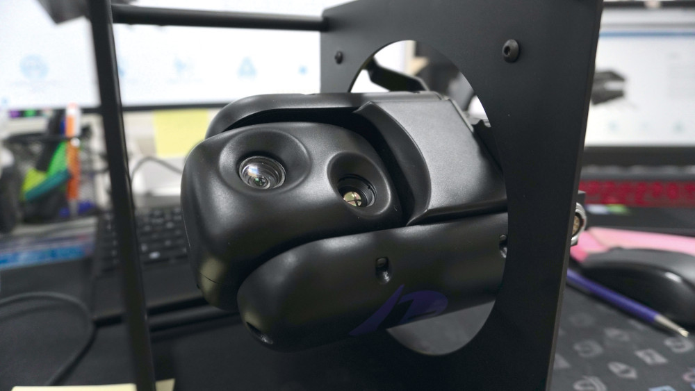
(Courtesy of UXV Technologies)
Rory Jackson charts the latest advances in gimbals technologies and offers some pointers to future trends…
The proliferation of small consumer UAVs in the early 2000s gave rise to very small, lightweight camera gimbals, which in turn propagated highly useful tools and expertise for engineering miniaturised motors, control boards, housings, windows and other related parts.
Nowadays, the rise of highly sophisticated and powerful autonomous vehicles in every terrestrial realm has pushed the creation of new gimbal models that strike a middle ground between the consumer UAV gimbals and the far bulkier, heavier ones of crewed aircraft. These new systems enable long-range surveillance, mapping and other missions by commercial, civil and defence operators, who now make up much of the customer base for uncrewed systems.
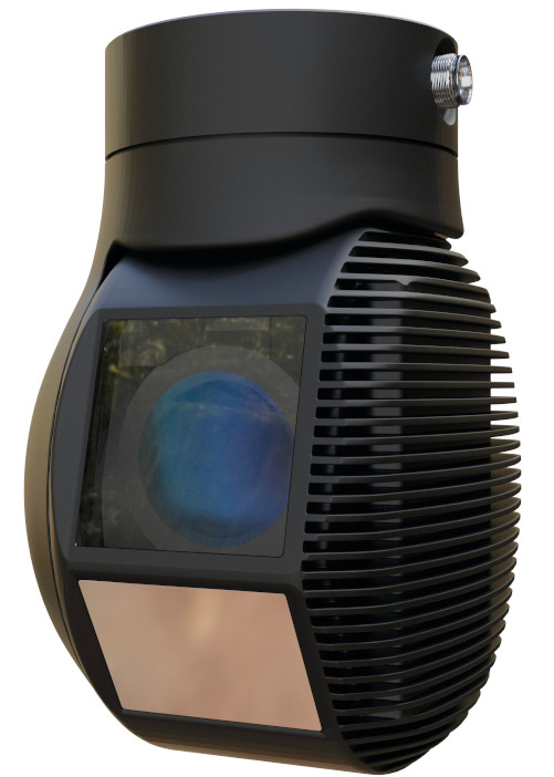
This new generation of gimbals incorporate the latest high-resolution EO, and cooled and uncooled IR cameras, designed for viewing targets more than 10 km away. They also carry the latest technologies in stabilisation, video processing and AI data analytics for example.
These latter technologies are enabling the gimbals to achieve more sophisticated classifications and higher resolutions of data than ever, and in real time. Advances in them are dictated by the skills of software engineers and the quantity and quality of processors that can be packed into the minimal dimensions of each gimbal.
With more processors comes more heat though, as well as less space in which components for extracting that heat can be fitted. But as awareness grows of what uncrewed systems can do for all sorts of applications, so too does the demand for increasingly intelligent and reliable gimbals.
That demand has therefore added another layer of new trends and technologies to this latest generation of gimbals, to fulfil the need to add intelligence and reliability to them without adding weight or heat. These trends and technologies first emerge in the design and prototyping phase of a new gimbal.
Design and testing
The actual tools for designing and simulating new gimbals have changed little over the past 5 years.
The nature of the autonomous systems market is such that with every week a high-end gimbal maker will begin planning a new project, with some customer wanting to integrate, say, a new IR camera, connector, vibration damper, video encoder and so on.
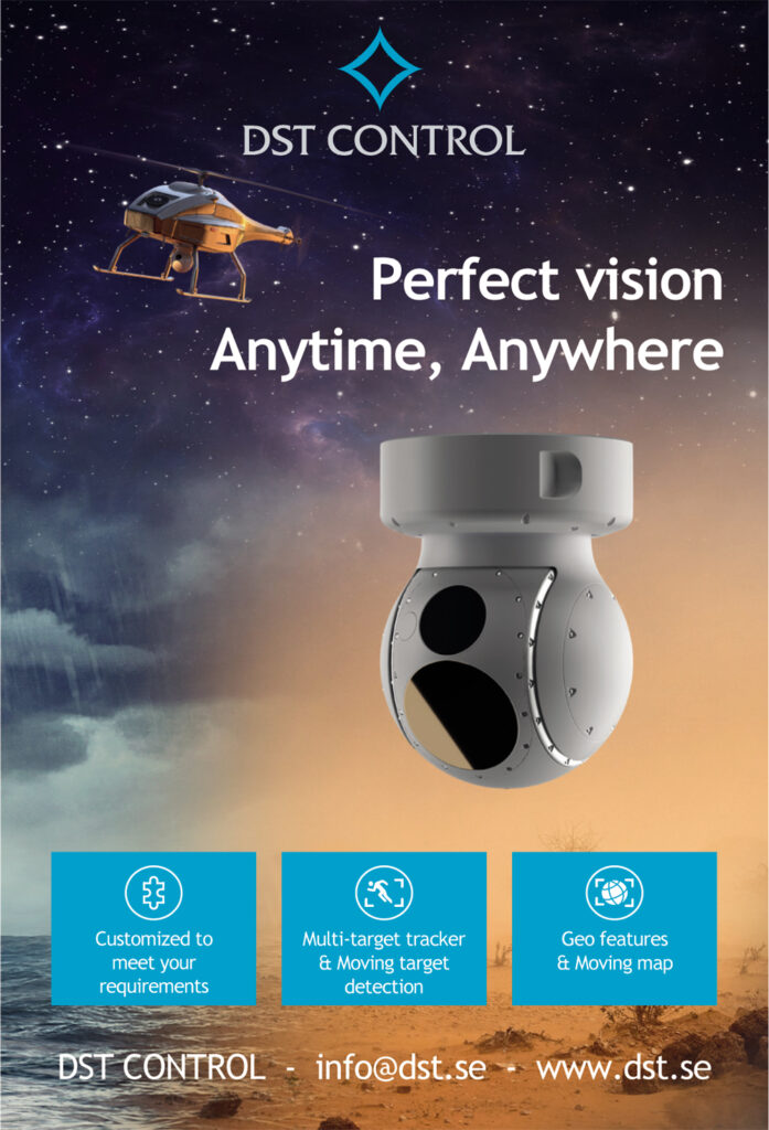
(Courtesy of DST Control)
The effect of this is that the most successful gimbal companies are generally those who have adopted a highly modular or open (or both)architecture with great swap ability of internal components.
This modularity shortens the design process and lead times of any new or custom gimbals. An all-new system can quickly be conceived by calculating high-level ‘budgets’ for weight and power consumption, which then feed into whichever other parameters are critical for the intended customer. Those figures then make it a straightforward and logical process to select components for power, housings, glass, motion control, data processing and so on.
Also, a bespoke modification of an existing high-end gimbal can now be prototyped within 3 or 4 weeks of the initial request, without the need for any in-house metal-cutting or fabrication, making these sophisticated and expensive systems some of the quickest to turn around relative to their complexity.
A key reason for the minimal changes in design software is that most gimbal companies take a hands-on approach to development, preferring to run just a few high-level simulations of new architectures before moving quickly to real-world testing and iteration of prototypes, and the more tangible and trustworthy data that brings.
That said, testing practices have also not undergone any major changes, given that certification requirements and demands vary from one customer to the next, and that most military-standard and other regulation-specified tests are carried out by certified third-party facilities. Gimbal suppliers wishing to go the extra mile though will use their own vibration tables and environmental chambers to benchmarks in excess of targets required for certification.
Notably, some companies are trialling their gimbals’ capabilities in stabilisation, pointing, tracking, zooming and so on by wheeling or flying them within sight of well-known landmarks and other visual markers in their local areas.
Such tests have the advantage of being easy to control. A UGV or UAV test platform can be pre-programmed to repeat the same route of waypoints and transit speeds over and again. Test engineers can also select days of similar weather patterns, to ensure different gimbal configurations have the conditions to produce data of similar clarity.
The video and imagery captured from each test can then be compared side by side or overlaid onto each other (or with other reference imagery and charts). That helps identify exactly where data quality is being gained or lost, and investigate which hardware or software modules ought to be fine-tuned, or the impact that differences in weather or other conditions have.
It is also becoming more common for gimbal manufacturers to reach out to customers for beta testing, sending their newest models or upgrade kits to trial how they can be used (or broken) on different missions and vehicles. This can include virtual or bench tests to validate key operational parameters such as slew rates before integration onto a vehicle, to ensure it is safe and worth attempting the kinds of live tests that can cause significant shock to gimbals with below-par capabilities.
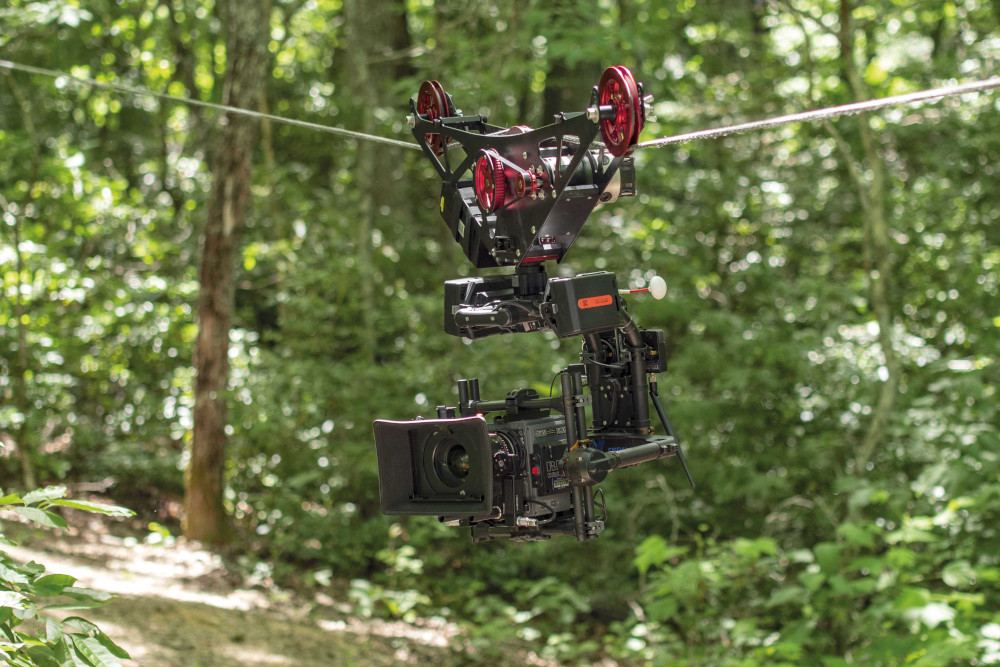
Professional cinematographers for instance routinely conduct filming work using uniquely dynamic manoeuvres and peculiar varieties (or even the absence) of vibration isolators between gimbal and platform. It can be difficult for gimbal manufacturers to anticipate exactly how such users will be using their gimbals, so the beta testing approach can be useful before commercially releasing a new model.
One parameter that high-end gimbal developers have a particular focus on is the balancing of their systems, often seeing it as a gimbal’s most mission-critical quality. Having a well-balanced gimbal makes an enormous difference in terms of stabilisation, power consumption, pointing, motor heat output and essentially all the other areas affecting performance.
Although they have their limitations, CAD tools can actually be highly useful in simulating the balance across a gimbal(and approximating its centre of balance, or CoB) so long as each sub-component has been thoroughly defined in terms of its own weight and CoB.
(Courtesy of Freefly Systems)
After that, prototype balance tests can be run in similar ways to how car wheels are tested with new tyres. The gimbal can be spun under close observation – to obtain data such as current, vibration and motor position – so that engineers or automated test software can mark where counterweights (or other attempts at manual calibration) are needed to balance out the gimbal in all axes.
Mechanical stabilisation
Obtaining high-resolution imagery and video depends critically on keeping gimbals stable, particularly when pointing at far-off or moving targets.
Mechanical stabilisation systems consist largely of BLDC motors and motor controllers. An increasing number of gimbal manufacturers are therefore choosing to specialise in the design of e-motor systems in-house, to control how they are optimised for parameters such as size, weight, latency, power efficiency and motion smoothness.
For instance, field-oriented control(FOC) systems are highly beneficial, as they enable a sinusoidal, smooth-wave output of movement instructions from the motor controller to the motors in charge of each axis of rotation. Traditional control by trapezoidal commutation makes for a much more ‘jerky’, staccato output of rotation orders, meaning reduced precision and energy efficiency than gimbals using FOC.
High-end gimbal companies are therefore developing their competencies in FOC, both in sensored and sensorless designs. The latter are less costly and more reliable, although the former might be better for many gimbals owing to the more precise control and low-speed torque they can achieve.
Such companies are even exploiting new types of small electric motor technologies, including some of those we discussed recently (see issue 42,February/March 2022). These designs can feature highly useful qualities for gimbals– for instance, if a gimbal’s e-motors are designed with ironless stators, they will not exhibit ‘cogging’ torque ripple.
As a result, each motor’s motion will be far smoother than those with iron stators, and its positioning will be more accurate, resulting in much clearer imagery from the gimbal when tracking and zooming in on moving targets.
Ironless stators are also lighter, which provides major improvements in power-to-weight ratios, meaning they contribute to longer endurances between recharging or refuelling, with more data gathered and processed per mission.
Digital stabilisation and video processing
While mechanical stabilisation remains the first and most important step for clear and precise imagery, quality digital stabilisation is still a useful differentiator between high and lower end gimbal systems.
Ongoing improvements in GPU and SoC technology are motivating high-end manufacturers to adopt more powerful engines for image enhancement. While silicon shortages still pose an issue for mass production or price reduction of such systems, the small-volume, high-price nature of the professional UAV market means there is still plenty of demand for gimbals running on the latest processors.
As such, engineers are upgrading to newer products with up to eight times the performance of their predecessors. Some companies meanwhile continue to release new microcontrollers that gimbal manufacturers rely on for enhancing their data processing as well as control signals, which can feed into digital and mechanical stabilisation in critical ways.
(Courtesy of Embention)
These are also key to providing a detailed application layer interface or companion computer through which end-users can adjust a gimbal’s mission parameters in a straightforward manner.
Beyond digital stabilisation, other intelligent functions depend on the video processors of gimbal manufacturers, and today’s uncrewed systems customers expect advanced video processing functions such as target classification, continuous zoom, sensor data fusion and smart overlaying from their products.
At a more fundamental level, the video processor is also responsible for the number and quality of video channels that can be encoded, which can directly limit the number of cameras per gimbal or the number of gimbals per vehicle.
The key problem lies with the ability to fit increasingly large and powerful video processing units inside the tight space of the gimbal without it resulting in excessive power consumption or overheating on the part of the processor.
Of course, these issues can be circumvented to a high degree by putting the video encoding and processing systems outside the gimbal, somewhere else on the vehicle (if the density of the electronics inside the vehicle do not cause build-ups of heat that are inaccessible to heat extraction systems).
While that can lead to extra cabling and internal space concerns for the vehicle OEM to deal with, having a separate but still fully compatible processing system can nonetheless give considerable cost savings and design freedom over fully integrated gimbal-and-processor systems.
As a halfway measure, some designs allow easy swapping-out of external GPUs through open architecture frameworks, to allow easy upgrading and dropping in of anyone’s classifier. That also means the end-user isn’t reliant on or stuck with the gimbal manufacturer’s own components.
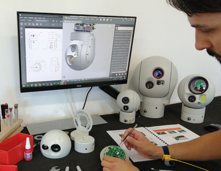
(Courtesy of Merio)
Beyond hardware concerns, the drive for reliability and intelligence in video processing functions is driving gimbal manufacturers to find ways of making the adoption and refinement of newAI modules easier. That is pushing the popularity of open software platforms driven by communities of programmers that will enable suppliers and customers alike to cherry-pick new algorithms and fixes to serve their needs.
That capability is especially important, as no one-size-fits-all software bundle can ever serve an entire uncrewed systems market segment. Even different police precincts for instance will want gimbal systems that can detect and classify cars based on varying differentiators, such as licence plate symbols, movement speeds, thermal signatures and signs of damage.
Geo-pointing and tracking
Besides motors and motor controllers, various technologies contribute to the data inputs needed for smooth and accurate geo-pointing, tracking and zooming of gimbals onto targets. These can be especially critical for military and search & rescue users, whose UAVs maybe racing against time to find people or objects in very unstable environments, as their gimbals will need to compensate for motion from multiple sources.
While most of the factors contributing to geo-pointing relate to sensing data, a key mechanical component worth considering here is slip rings. While these are generally a well-established technology, any gimbal using low-end (or no) slip rings will be largely incapable of continuous panning. That can cause major issues when geo-pointing about the platform, as after a certain panning distance the gimbal will need to reset.
One of the foremost sensing technologies for gimbals with sensored motion control is the use of encoders for position feedback data. High precision, resolution and linearity (or low non-linearity) are some of the most critical encoder parameters being eyed by gimbal manufacturers.
Different encoder designs come with their own parts, form factors and performance qualities that should be considered before selecting them. Magnetic encoders for instance need a magnet as a point of reference, and while BLDC motors provide these in abundance, if the encoder’s sensing circuit fails to detect a magnet it will either output a random angle or an error message.
Optical encoders meanwhile use a sensor to take note of positional changes as light passes through a patterned wheel or disc, but the latter can become contaminated by dust and moisture more easily than magnetic encoders. Hall effect magnetic sensors have become particularly popular among high-end gimbal manufacturers, as they can be made more compact than other kinds of encoders, and can also provide higher data sensitivities and resolutions.

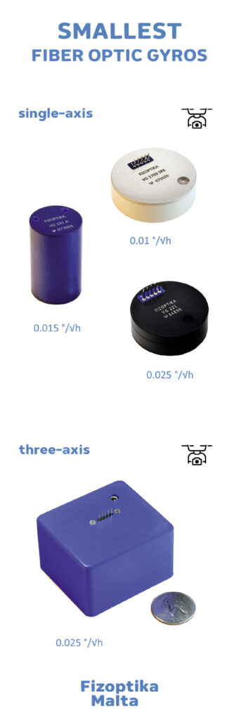
Inertial sensors meanwhile continue their gradual improvements in performance versus size and weight, and gimbal manufacturers will periodically update their products with newer inertial systems as they come out, particularly as MEMS systems become more powerful and FOGs are designed smaller and flatter, although the latter is rarely used in UAV gimbals except in systems destined for GNSS-denied conditions.
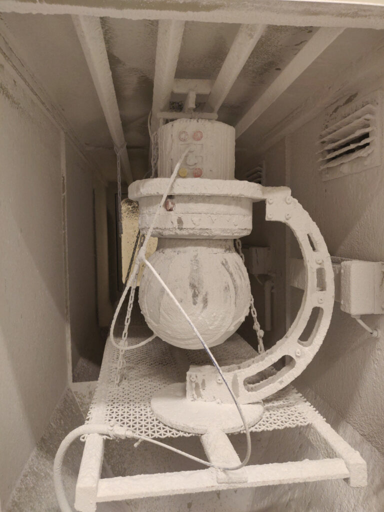
One of the more striking changes to look for in the future might be the adoption of temperature-controlled IMUs, as the performance and reliability of inertial sensors will waver depending on the surrounding temperature; some test results indicate that they work best at roughly 60 C.
Temperature control may be achieved in two ways. The first is by testing IMUs across different temperature conditions to develop algorithms and maps for correcting temperature-driven measurement drifts. The second is by modifying a gimbal to include resistors or other kind of heater that will warm the IMU to a target temperature.
The latter is the more thorough and trustworthy approach, but of course it will increase the thermal management burden of the gimbal’s subsystems.
Adding a dedicated heater for the IMU can also conflict with the need to cool internal electronics and IR sensors though, so significant insulation and isolation features in the IMU’s PCB, along with judicious use of aluminium heatsinks around the heater, can help. Lastly, it is vital to remember that today’s high-end gimbals are almost all geo-referenced systems. Wherever possible, the gimbal must ‘know’ where it is, in GNSS and altitude terms, and be able to discern where the target is based on pointing direction.
Even when there’s no ‘target’ – in filming work, say – high-resolution GNSS data can be critical for determining acceleration and velocity to compensate for issues such as drift in the horizon or inertial readings.
In this regard, the UAV itself can once again be a source of vital data for the gimbal. As precise pointing and tracking requires not only GNSS and altitude information but also compensation for the host vehicle’s heading – as this has an impact on the relative angle between gimbal and target – integrating a data connection into the gimbal for taking GNSS heading information from an external source such as the autopilot is a straightforward way of improving the gimbal’s tracking and pointing accuracy without needing to make major alterations to its architecture.
However, the speed and resolution requirements of data inputs for gimbal pointing are generally much higher than those of uncrewed vehicle navigation systems. Manufacturers looking to guarantee a minimum level of pointing accuracy can therefore aim to use or provide a dedicated navigation module off-board from the gimbal, for providing real-time, high-precision updates on position, heading and so on.
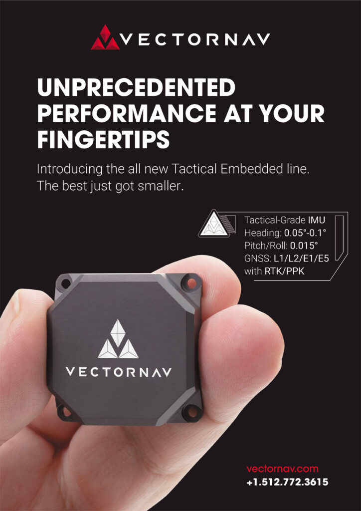
That can be crucial for multi-rotors, USVs or UGVs capable of rotating onthe spot where vehicles’ headings are often unclear, and hence can come with different combinations of subsystems such as dual GNSS antenna inputs, high-end inertial sensors and barometers.
The frequency of laser range finders across gimbal products is also increasing in response to a demand for accurate geo-pointing. Millisecond-rate data updates on the distance to a target, as well as the rate at which that distance is changing – and by extension the velocities between vehicle and target – inform the gimbal very close lyon how best to zoom, pan, tilt or roll to continue tracking it.
The high quality of this information is why defence and security gimbals come increasingly with laser devices, given the importance of target tracking to these users, not to mention their ability to pay for such expensive laser systems.
Structure and materials
Materials choices in gimbals, particularly with regard to housings, continue to follow the same logic as most other sections throughout a UAV, being based on whatever quality the gimbal maker and systems integrator wants to eradicate most. In general, plastics are ideal for reducing materials costs, carbon composite is best for reducing weight, and aluminium wins out for reducing or extracting heat.
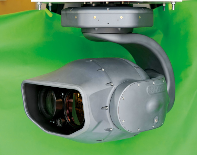
(Courtesy of Shotover)
With the most prominent trend in gimbal design being the integration of new and more powerful GPUs, it is becoming common for new high-end gimbals to be made mostly from aluminium, with strategic placement of composites and plastics in a few places where they can be afforded. Leading manufacturers meanwhile continue to experiment with different materials such as new magnesium alloys and nylons to identify where improvements in thermal stability, weight saving and cost saving could be gained.
One of the more interesting trends among newer gimbals is the use of dual arms in the tilting axis – it being the outermost axis and hence the one that directly couples the gimbal ball to its base – rather than having a single tilt arm on the side, as has been more common.
That trend has been motivated in part by the growing take-up of autonomous ground and ocean vehicles. A dual-arm gimbal provides greater strength than a single-arm version, and can therefore slightly better handle being mounted head-up atop an uncrewed vessel or ground system.
Also, continued strong demand for autonomous ISR capabilities from special forces users, who aim to mount gimbals on high-speed uncrewed aircraft and pull heavy g-forces and dynamic manoeuvres with them, has also led to greater use of two-arm gimbal frames, both for longer product life and more stable retraction or extension from gimbal bays inside their UAVs’ fuselages.
And in their labs, gimbal makers routinely experiment with new structural techniques, such as ways of using PCBs for structural loading to reduce total part counts, or additively printing new and complex structural parts that can damp vibrations or handle shocks and other loadings effectively.
Future prospects
High-end gimbal products of the future look likely to continue the trend of becoming larger and larger, in order to package bigger lenses with more optical zoom for users across sectors such as defence, cinematography and wildlife protection, as well as having bigger motors and GPUs to produce clearer imagery with more actionable data.
That could mean gimbal manufacturers approaching a hard barrier in terms of how much heat can be dissipated, or concerning the expense of losing a gimbal system through mechanical damage. However, some developers hint at new materials and techniques for thermal and structural robustness that remain undisclosed for the time being.
Whether these will come to light in future generations of gimbals remains to be seen. Either way, that such experimental technologies exist at all should be clear evidence that the world of gimbals for uncrewed systems is set to continue being a hotbed of scientific advances for many years ahead.
Acknowledgements
The author would like to thank Tabb Firchau and Matt Isenbarger at Freefly Systems, Magnus Sundtedt and Jan-Erik Stromberg at DST Control, Frank Severinsen at UXV Technologies, Javier Espuch at Embention, Fabrice Perodi at Merio UAV Payload Systems, Robert Kubis at Shotover, and Guy Bowie and Luis Nieves at Collins Aerospace for their help with researching this article.
UPCOMING EVENTS


