


Autopilots
Rory Jackson discovers how flight controllers are evolving to become highly intelligent, safety-rated systems rather than simple ‘black boxes’
Over the last five years, autopilots for uncrewed systems have evolved to become much more than ‘black boxes’ responsible only for automated management of aerial, ground or ocean crossings in executing keyed-in GNSS waypoints.
For professional and highly autonomous vehicles today, high-end flight controllers are expected to embed or interface with computer-vision AI towards advanced functions such as object detection and classification, collision avoidance, gimbal target tracking and GNSS-denied navigation.
Inflows and outflows of data regarding an autopilot’s central processors can now pass through so many sensor connections, edge computers, bridging hubs and signal converters that it is not incorrect to think of the ‘autopilot’ as a cluster or ecosystem of different devices surrounding the central flight controller.
Competing autopilot products will vary in how much or little extra they carry in terms of GPUs, IMUs, GNSS receivers and so on. Depending on the solution, some parts may be omitted; others may be installed in triplicate for redundancy.
Either way, there is a growing need for AI, along with the processing power to enable it, in today’s autopilot systems, as well as copious connectivity for linking sensors, payloads, secondary computers and much more to the central controller, be it via Ethernet, controller area network (CAN) bus, mobile industry processor interface, camera serial interface (MIPI-CSI) or one of the many other protocols for which autopilot manufacturers must account.
As the uncrewed industry wants more powerful hardware and in higher quantities, autopilot makers are expanding their facilities, with many having produced thousands of autopilots in 2023, and planning to triple or quadruple that number this year.
With SAILs unfurled
In addition to key regulations, such as DO-178C and DO-254, which are critical standards for autopilot software and hardware, new specific assurance and integrity level (SAIL) standards have been published by the European Union Aviation Safety Agency (EASA), with the Federal Aviation Administration (FAA) to publish close equivalents of its own.
These lay out the degree of risk to be undertaken – and hence the hardware and software robustness required – by an uncrewed system in operation, going in tiers from SAIL-1 to SAIL-6, indicating the lowest to highest levels of risk certifiable under a Specific Operations Risk Assessment (SORA) flight application.
The higher SAIL categories of SAIL-5 and SAIL-6 (which might pertain to very large UAVs flying over populated areas) require particularly comprehensive validation and verification of UAV subsystems, potentially via Type Certification. Autopilots for such applications will be scrutinised for each step of how they have been designed, programmed, manufactured, tested and integrated.
Other SAIL standards are in the process of being written, with SAIL-3 closely influenced by the DAL D level of DO-254, and SAIL-4 yet to be defined. Key functional requirements of autopilots going forward will include proving at least two key parameters. The first point is the rarity of failures in such systems; it is likely that SAIL-3 will require the probability of failure to be below 1 in 10-4, while SAIL-4 or SAIL-5 may specify 1 in 10-9.
The second proof point will be how reliably autopilots geofence their platforms against accidental breaches of permitted airspace. The software and hardware must robustly minimise the probability of an accidental slip outside of geofenced boundaries, and then stop the vehicle from going much further in the highly unlikely event of a breach.
One way to achieve that is to write processes into an autopilot for opening a parachute if the breach has been caused by severe damage, forcing the aircraft into an uncontrolled descent.
Alternatively, if a UAV is too large to be stopped or slowed by parachute, machine-vision software could analyse the terrain below and calculate the best control outputs (using whatever flight-control surfaces remain intact) for a safe emergency landing. Embedded maps from local authorities could alternately delineate acceptable locations for emergency landings.
Either way, requirements will have a considerable impact on how UAV autopilots must be designed and built, particularly regarding the kinds of components, functionalities and tests that will need to go into them, and their ancillaries.
His ARMs wide
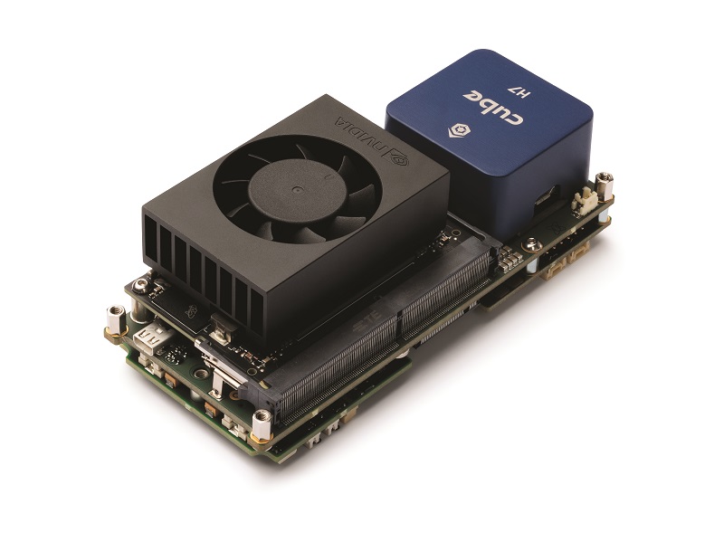
At the veritable ‘core’ of every autopilot is a CPU or microcontroller; nowadays, likely to be built around one of the latest ARM processors, responsible for the processing of flight-critical information inputs into control surface commands, but as integrity requirements increasingly equate hardware’s airworthiness level with its level of redundancy, it is becoming more common for autopilots to come with two, three or more such cores.
This requirement spirals outwards, as UAVs cannot claim real redundancy if they have four autopilot computers and one GNSS-IMU. Hence, complete autopilot solutions designed for higher-risk, higher-end applications are being built with not just multiple microcontrollers but growing numbers of GNSS receivers and antenna inputs, IMUs, data-link interfaces, and traditional aviation sensors such as pitot tubes and barometers, which have been proven to be reliable sources of information over their decades of use.
While all these systems are key to a good autopilot system, some bear closer scrutiny than others. For instance, a good gyroscope defines for many the quality of the whole autopilot, as having reliable angular rate data makes countless potential autopilot faults easier to resolve.
But, for sheer controllability, choosing a central processing unit (CPU) with the right architecture and internal features is the key to safeguarding against dire issues, such as encryptions against the hostile seizure of data from an uncrewed system, advanced manoeuvres needed for flying amid obstacles or below radar, or smart behaviours for flight safety amid jamming or spoofing (which we will discuss in more detail).
It is increasingly common for integrators to opt for a GPU or a system-on-chip (SoC) type of machine to handle such advanced functions – and a range of robust systems are available – but they take up significantly more weight and power than a CPU, and are far easier for hostile actors to detect, given their thermal and electromagnetic (EM) emissions.
Hence, some UAV autopilot manufacturers remain committed to choosing the right CPU for integrating precisely the code needed for the mission and environment, and condensed to avoid wasting weight, computational power and electrical power, especially if aviation laws end up requiring triple-redundant CPUs for autopilots to be certifiable.
Naturally, the gradual increase in redundancy requirements comes with certain risks to uncrewed systems engineering and manufacturing. For one, making an autopilot triple-redundant will obviously triple the number of chips it needs, driving up the pressure on already strained supply chains of silicon.
A more redundant autopilot inevitably requires more core and ancillary systems to support it, driving up the size of the UAV required to carry a given payload mass. Hence, autopilot manufacturers are carefully scaling and selecting parts with SWAP to reduce the need for a 40 kg UAV to deliver an 800 g payload.
Autopilot developers are working on alternate configurations and means for guaranteeing that uncrewed systems continue operating normally, keeping within safe boundaries in the event of key subsystems failing.
GNSS-independent configurations
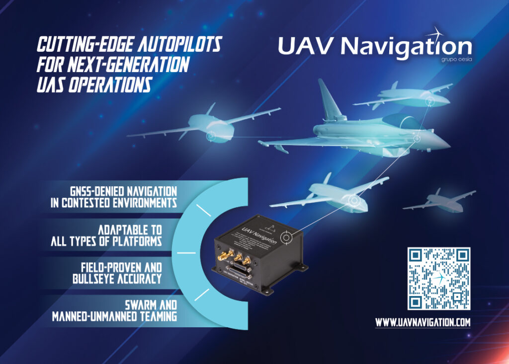
A few new systems are coming with integrated or optional vision systems for smart use of optical positioning references to compensate for drops in GNSS or IMUs, and to satisfy authorities that loss or spoofing of GNSS-inertial inputs will not result in losing the aircraft or its navigation integrity.
This is critical as even triple-redundant, multi-constellation GNSS receivers may be undone by a singular jamming attack. Additional observer functions and sensor integrations for position estimation will be increasingly critical to certifiable autopilot arrangements in the future.
Visual navigation is now widely used by indoor and urban UGVs, given that GNSS struggles in cities and buildings, but some UAV autopilots are now integrating cameras and machine-vision systems for recognising specific points or patterns of terrain amid GNSS spoofing or jamming.
It follows that extremely robust logic for detecting spoofing – such as constant cross-referencing of GNSS data with accelerometer or pitot tube readings to immediately notice conflicting speed data indicative of GNSS inaccuracies – is imperative for autopilots to determine when to disregard GNSS data.
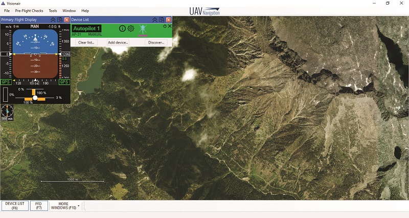
For effective visual navigation capabilities, it is prudent that autopilots can either be embedded with, or generate in real time, their own georeferenced imagery of the ground to leverage terrain visuals in known areas for accurate self-geolocation.
In unknown areas, self-geolocation may be impossible with vision alone, but a robust visual odometry can minimise drift to within 1% error, and potentially enable a UAV to return to a known area or its launch and recovery point.
Some autopilots are being designed to leverage inputs other than visions of terrain and ground structures, as thick cloud cover beneath high-altitude UAVs or the absence of terrain for USVs and maritime UAVs would leave such vehicles without reference points, and therefore especially vulnerable, with one company planning to use the sun as an autopilot reference point.
Many precedents for this exist. For centuries, sailors navigated by the sun using sextants and other tools, and some satellites and crewed aircraft today reference the sun for navigation. So, a system for autonomous solar navigation could be built around cameras to recognise the sun (thermal cameras are likely to be used by USVs and low-altitude UAVs to prevent overcast conditions from causing failures) and use its position relative to the ground or horizon to feed internal solar-tracking models.
Test results indicate that an autopilot designed with such a function can estimate heading accurately and smoothly, and be able to do so for long periods of GNSS outages.
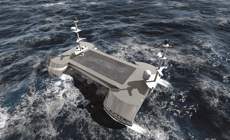
On the ocean
While the subject of autopilots tends to focus particularly on the needs of uncrewed aircraft, there is a growing supply of marine autopilots in the industry, as well as multi-domain autopilots that can be used for both air and sea (and sometimes also land) vehicles.
Such solutions must be designed around an integrated ecosystem, incorporating steering control and propulsion control, as well as the appropriate electronic navigational charts and integration of radar, automatic identification systems (AIS) and other vital marine navigation safety systems. Depending on the context, forward-looking sonars and doppler velocity logs may be useful for marine navigation and collision avoidance.
The front end of such software must accordingly be built for USV-applicable mission planning, localisation, steering and power control, with additional features in the back-end programmed with alignment to appropriate maritime standards.
For instance, USV autopilot engineers in the UK are moving towards adherence with the UK Maritime & Coastguard Agency’s (MCA) Workboat Code, Edition 3, Annex 2 for ROUVs (remotely operated unmanned vessels, as the UK MCA calls them). Published in December 2023, this covers safety standards for USVs in failure mode, how to handle hot handovers of control, assurance requirements, and other critical factors for marine autopilot software and hardware.
On top of this, one must distinguish between the autopilot requirements of smaller versus larger USVs, given that professional, uncrewed vessels now range from less than a metre to dozens of metres in length, and in some cases (particularly in large-scale freight and defence) even hundreds of metres.
Professional 3-12 m USVs can get by on a computer system good enough to enable autonomous navigation with software processing and sensor interfacing for obstacle detection, collision avoidance, anti-grounding and potentially a few simple vessel system controls, such as bilge-pump operation algorithms.
For USVs closing on or exceeding 20-25 m in length, a very tight integration of all these capabilities with all vessel systems is likely to be needed, along with added intelligent functions, such as virtual anchors or a return-to-base mode upon loss of control.
All types of USVs operating at sea must combine their use of radar, vision, AIS, sonar and so on with the requirements of the Convention on the International Regulations for Preventing Collisions at Sea (COLREG) to satisfy maritime regulation agencies of safe behaviour – even if certain COLREGs can suffer vague wording regarding such things as value judgements on safe distances and clearances between one’s vessel and a nearby vessel, which merit real-time analysis of a USV’s speed, attitude and surroundings by an autopilot.
Designing an autopilot
Despite autopilot products being ordered in larger quantities, integrators still frequently want them to be tailored to parameters specific to their vehicle, environment and mission set. Wherever possible, autopilot suppliers will try to cater for very specific requirements through tuning software, as customising hardware is an expensive and arduous process, typically affordable only to large customer orders.
To that end, autopilots are increasingly designed with hardware architectures that can run different versions of navigation and control software, depending on which of five discernible categories of uncrewed system are to be operated. These are multirotors, fixed-wing aircraft, VTOL-transitioning aircraft, attritable UAVs and USVs.
To take a version of software designed especially for one of these vehicle types, and change it to control another one takes immense time and effort, not purely in development but also in the exhaustive simulated, laboratory and field tests necessary for validation.
Additional sub-categories and nuances exist within each vehicle category, but they tend to boil down to small functions that developers routinely adjust for without too much difficulty. For instance, a company might design a fixed-wing UAV autopilot for systems to be launched by catapult and recovered via parachute landing, but then need to change 10% of the software code at the most to adapt it for UAV integrators who want to take off from and land on a runway.
To design the autopilot correctly for each customer’s needs it is common to start with a request for information (RFI) on their platform, particularly its configuration, the layout of control surfaces, its operating envelope, and its modes of launch and recovery. Compiling these on a sheet of paper defines the customer’s functional requirements.
The autopilot maker can then identify any potential risks that must be mitigated in the autopilot’s functions, how many units must be delivered (and hence how far its design must be tuned for automated manufacturing), the timeframe in which they must be delivered, and hence an estimate of the high-level design adaptation work to be done.
Going deeper within those levels requires additional information to cater for vehicle-specific qualities. Ensuring controllability, for instance, mandates details on maximum take-off weight (MTOW), expected moments of inertia, the size of control surfaces and expected vibrational frequencies from subsystems. Customers’ plans on vehicle structures and subsystem mounting may be crucial for spotting conflicts or trade-offs; for instance; if high computational power is needed in a hermetically sealed fuselage, and then airflow cooling could become impossible.
With such information, autopilot engineers can proceed to define appropriate parameters for the use-case, enter them into a hardware-in-the-loop simulator, and start testing and iterating towards an embodiment that will result in the vehicle behaving as desired.
Trends likely to test such development processes and design loops in the years ahead include newer generations of uncrewed vehicles that move faster, with higher dynamics than current software control loops can handle.
Autopilot designs with high levels of modularity and open architectures will be best placed to adapt for these operational requirements, as well as for regulatory dictums on how software modules and hardware components can achieve critical safety ratings.
Towards bulk manufacturing
Manufacturing and validating autopilots is not dissimilar to the mass production of most other high-end electronics, save for some specifics relating to quality control such that safety ratings are met for aviation authorities, according to pertinent standards such as DO-254 or EMAR 21, depending on the use-case.
The process begins with sourcing components from distributors, with products authorised for use in the industry and optimised for bulk supply, with additional checks of component quality being a vital intermediate step.
To link these components the autopilot maker needs a verified manufacturer of high-density, interconnect printed circuit boards (HDI PCBs) – not an easy find as such boards are extremely complex and not all manufacturers can deliver them to the quality needed for hitting the higher SAILs or other aviation standards.
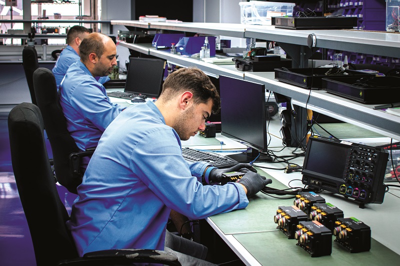
Manual visual inspections of the received boards can be painstaking, but also hugely valuable to ensure they have arrived clean and with good copper cladding, grounding, surface treatments and so on.
Once satisfactory, the HDI PCBs can be put through high-speed production lines, with automated assembly and optical inspections. Such lines can be powered with standard manufacturing systems, but very tight tuning, control and integration can be critical to prevent imperfect placements or alignments of board-mount components on the PCBs, or anything else that would fall short of the targeted level of certifiability.
The assembled and quality checked board modules can then be flashed with the basic software and firmware for vehicle control, navigation and other functions, before being assembled into complete modules with enclosures, cooling fans, ruggedisation and so on, per the design specifics of the product.
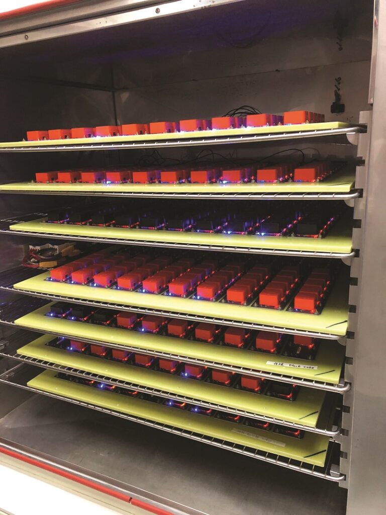
Following this could be rounds of testing, from visual checks to automated test procedures of all physical interfaces and separate functionalities, to random or particular selections of units for deeper quality checks, such as shock, vibration, EMI and thermal chamber-test regimens, defined and well-established across various military and aerospace standards, as well as flight tests and simulator tests.
Many manufacturers find testing throughput to be a production bottleneck, to the point that some are circumventing it by building test rigs that hold scores of autopilot modules at a time, all connected to a measurement device or simulator, such that batches upwards of 50 units can be subjected to intense shock, cold, heat and other extreme conditions at once in controlled and repeatable conditions.
Standards in software
The evolution of standards to which software programming must adhere is a subject that autopilot manufacturers pay close attention to, affecting guidelines for the MAVLink protocol that is central to many autopilots, as well as for payload buses, compatible board configurations and application-specific protocols, such as military protocols for the integration and connection of UAV autopilots, subsystems, payloads, ground control stations and so on.
For instance, the new RAS-A protocol, for use in systems for the US Department of Defense, has been designed to improve over MAVLink in vital ways, such as better handling of system IDs across network layers through point-to-point communications.
Autopilots are also being programmed for more application-specific integrations, such as new cameras prized by industrial mapping and photogrammetry customers. Software standards for interfacing with them are being established to smooth the work needed for end-users to be able to plug in such cameras and still see their data in their user interface.
The same can be said for components such as data links and ECUs, as each customer may prefer a different solution. Hence, an API and drivers for each of them are key to swapping and configuring them in a straightforward manner within a unified interface. Coding software patches and features for such functions is a vital step towards minimising the degree of training needed for new uncrewed systems technicians and operators.
While many tools are available for automating code production, and ensuring software follows regulatory and mission requirements, good procedures and well-trained programmers remain key to robust software with multiple features and minimal error. Other assets are also vital for reliable, smooth running. High-end compilers, for instance, can be expensive, but tend to be updated frequently to prevent bugs or insufficiencies that can hamper the throughput and quality of autopilot code.
On top of this are other useful tools for optimising the back end of software, such as code analysis solutions and cyclomatic complexity verification systems, which can gauge the complexity of a batch of code and indicate places where five lines of code could do the job of 15.

Future of flight (and ground and sea) control
In addition to certification standards continuing to evolve and define the requirements of autopilot design, engineering, manufacturing and testing, ongoing economic concerns such as labour shortages and the need to cut operating costs are likely to compound with defence services’ hunger for autonomous force multipliers.
This would result in a gradual transition towards fleet- and swarm-oriented autopilot configurations, with each autopilot not only designed for mass production at reduced cost, but also to function intelligently and intuitively enough to take much of the complexity of operating (or monitoring) uncrewed systems out of operators’ hands, decreasing the training and number of personnel required per uncrewed vehicle.
The emergence of standards on fleet management and swarming is inevitable, although they may take time to be formed. In lieu of those, one can expect next-generation autopilots to leverage a variety of technologies crucial to enabling different forms of swarm. These may include increasingly higher-end edge computers or cloud computing for real-time data processing and decision-making, as well as 5G and other advanced forms of data link for swarms to internally communicate critical information and potentially decide on formations, task allocations or rotations as a group.
Naturally, the use of these technologies will be influenced by the various bodies within the FAA, EASA and other aviation regulators tasked with defining safety standards on comms systems, cloud computing, AI and more across the ecosystem of current and future autopilot components, as is necessary for ensuring the advent of UAVs either leaves humanity’s skies and cities as safe as they were before or makes them safer still.
Acknowledgements
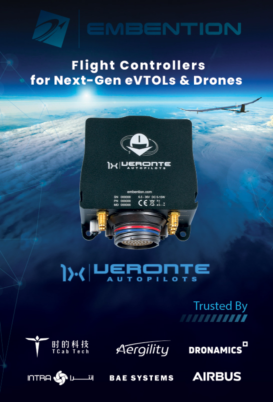
The author would like to give special thanks to Philip Rowse at CubePilot, Markus Achtelik at Auterion, Miguel Angel de Frutos Carro and David Pinta Sierra at UAV Navigation, Nigel Lee at Robosys Automation, Javier Espuch and Antonio Felipe Gómez at Embention, and Lukas Palkovic and Jozef Rodina at Airvolute for their help in researching this article.
UPCOMING EVENTS


