


Limbach 2400 DX and 550 EFG
Torque it up
Rory Jackson finds out how this company is developing engines with higher torque to match the growing demand for it in the UAV industry
We previously featured German aero engine manufacturer Limbach in UST 17 (February/March 2018). In that article, the company detailed its 7 kg L 275 EF two-stroke boxer twin that produces 18 kW and is aimed squarely at the kind of 25 kg MTOW UAV that has become the mainstay of aerial data and surveillance providers.
In the 5 years since then, Limbach has continued to expand its customer base and operations in the UAV sector. The growth and evolution of that market has prompted Limbach to focus on subsystem areas in its r&d that are centred on torque-to-weight ratio.
The reasoning lies in the customer base. The kinds of uncrewed aircraft their end-users are working on show a growing proportion of large UAV configurations. One (undisclosed) user even makes an airship that integrates three, four-stroke fuel engines to provide a distributed and vectored thrust system.
That trend towards bigger, heavier and more power-hungry UAVs explains Limbach’s r&d focus on increasing torque. As aircraft get bigger, they need more lift, which tends to mean increasing either the size or number of blades on each prop, so that it generates extra lift without needing higher revs. But a bigger or heavier prop requires more force to rotate it – in essence, its engine must generate more torque.
The company’s engineers have paid significant attention to two of its models in particular in this respect. One is the L 550 EFG, a modular expansion of the L 275 EF boxer twin (the focus of the article in our February/March 2018 issue). It is essentially the same two-stroke but has the crankcase and shaft extended backwards to accommodate an additional cylinder pairing, making it a four-cylinder boxer.
The ‘G’ in EFG stands for gearbox, one of which has been installed on the L 550 EF to reduce its speed and increase its torque at the output shaft more reliably than a belt or chain. The engine has also been fitted with a new starter/generator from ePropelled, to better satisfy the growing demand for high electrical power in UAVs for payloads and back-up electrical propulsion systems for greater redundancy in flight.
The L 550 EFG displaces 548 cc, produces 50 bhp at a crank speed of 7500 rpm, and weighs 15 kg without its gearbox, or 28 kg with it. It is predominantly aluminium, with a die-cast crankcase and cast aluminium alloy pistons and cylinders (as well as a nickel silicon carbide coating in the latter’s barrels). Although further rig testing is needed to fully validate numbers, present calculations indicate a peak torque of 96 Nm at the top crank speed.
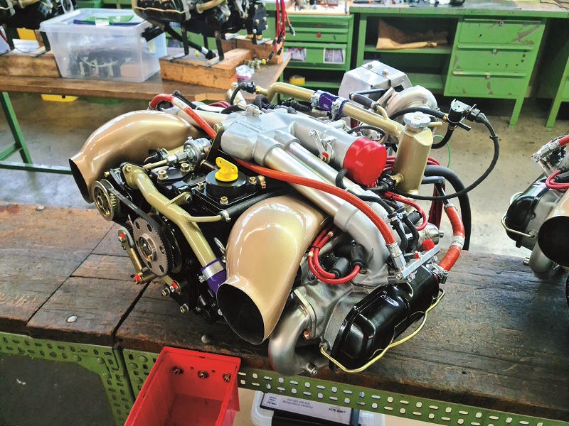
The other engine is the L 2400 DX, and it is Limbach’s most powerful unit. It has a dry weight of 86 kg, and at its peak power of 118 kW and 3000 rpm crank speed it produces 375.63 Nm of torque. It also comes with options such as a dry sump.
The bulk of Limbach’s r&d since our previous investigation has gone into four-strokes, hence our principal focus on the L2400 DX here, although we will also delve into the new features in the L 550 EFG.
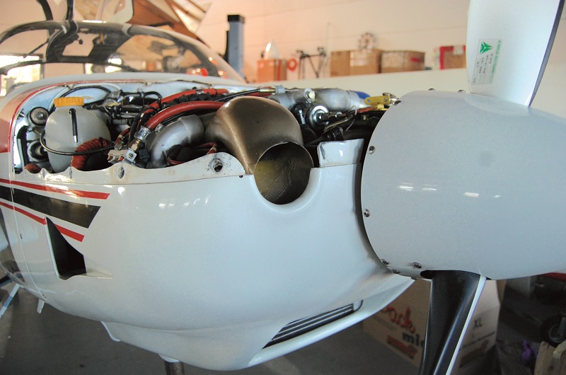
L 2400 DX operation
The L 2400 DX runs using electronic fuel injection and engine management, as is commonly requested by the UAV industry. It also comes with a ‘two-tier’ cooling system, which combines air and liquid cooling in different methods.
Air distribution for combustion occurs via an airbox on top of the engine, with an intake collector manifold sitting near the upper rear. The manifold houses the throttle, from which the airbox’s four distribution pipes run across the engine block and into the cylinders.
The manifold is cut from aluminium to save weight while maximising strength and thermal stability, although a fresh set of flow simulations is planned to optimise its design and construction, and to see if newer materials or technology could be exploited to improve the flow.
Intake boost comes from an exhaust gas turbocharger at the rear of the engine block, installed principally for altitude compensation as more and more UAVs conduct survey and mapping missions at increasingly high altitudes.
“We’ve therefore selected a model that can generate good boost pressure even at high altitudes and relatively low engine speeds of 3000 rpm,” says Sven Simmerkuss, development and test manager at Limbach.
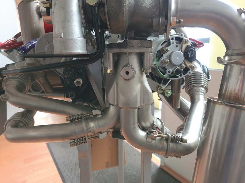
The turbocharger is a standard, single-scroll design, with each cylinder featuring an exhaust pipe running backwards and feeding into a single manifold collector that connects with the turbine inlet to drive the compressor shaft, and an EGT sensor installed in the collector.
Simmerkuss notes here that a twin-scroll turbo had also been tested with this engine when it was first designed, but it brought no advantages. The present design itself is a proprietary Limbach part, based on a series turbocharger from a third-party manufacturer.
Intake air from the compressor is first piped through to the charge-air cooler, which is optional as its optimal form factor and mounting spot depends largely on the end-user’s platform (particularly to ensure sufficient access to cooling air for the unit), before going to the intake manifold.
The company notes that the turbo is not a variable-geometry system. Instead, as Simmerkuss explains, “It uses an internal wastegate flap which is driven by a rod and is controlled by a pressure cell.
“The pressure cell on the other hand is controlled by an electric valve. This is done by the valve passing on the charge pressure generated by the turbine side of the turbocharger to the pressure cell.”
As soon as the boost pressure exceeds a limit value, it is released to the atmosphere by the ECU activating the valve. That limits the charge pressure generated by the turbocharger, and thus protects the engine from excessive power overboost and the engine knocking that comes with it.
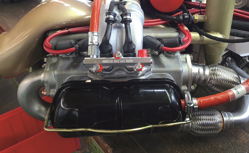
“Also, just above the intake ports, where each pipe runs into each cylinder, the manifold has plugs where we install our fuel injectors, so fuel enters the air stream at the very end, right before each cylinder inlet, so the mixing largely takes place within the tumble of the compression phase,” says Simmerkuss.
“Each pair of IWP 43 injectors – for each pair of cylinders – is connected through a bridge, which also mounts the fuel intake from our fluid line, with a single circuit of fuel going from the tank, through the engine and back to the tank with any unused fuel.”
The fuel piping thus runs across the injection nozzles for (in order) cylinders 4, 2, 1 and 3, ensuring a constant feed, before then running to a pressure sensor and then a pressure regulator, with unused fuel subsequently returning to the tank. Electric pumps powered by a generator feed the gasoline at up to 100 litres/hour through fuel lines optimised for a design pressure of 2.5 bar and to a limit of at least 6 bar.
In addition to the fuel pressure sensor, piping for an air pressure sensor is connected to a composite arched pipe running between the throttle and the air filter enclosure. Meanwhile, the throttle integrates a two-channel Hall effect sensor for position sensing, the second channel serving as an emergency back-up in case the first fails.
Power for the throttle position and other sensors and injectors can be provided using an optional starter/generator for the L 2400 DX – again, assuming the end-user chooses not to supply their own. This system has a 28 V DC output and is capable of up to 7 kW output, supplying the 9 A consumed by the engine during regular operations. A 14 V, 55 A alternator is also available.
“We’ve chosen torque over high speed with how we’ve designed and programmed this engine to function at its core,” Simmerkuss says. “Theoretically, we could have chosen to leave the torque increases to a reduction gearbox, as we’ve done now with our two-stroke 550 EFG, and as many companies do with their larger, more powerful engines, but we opted for a low-rpm engine.
“By designing and mapping the L 2400 to run at a low rpm, we avoid the need to add a heavy gearbox to what is already quite a big and powerful engine, and we maintain high torque at the output shaft for turning a big propeller.”
In addition to the peak values given earlier, the L 2400 DX is capable of a maximum continuous torque of 327 Nm, achieved at its top sustainable power output of 103 kW at 3000 rpm.
Engine management
The sensors connect to the ECU, which uses an Alpha-N control strategy. The throttle position sensor (TPS) provides one key input for the fuel/air mapping, and an engine speed sensor supplies the other.
Fuel flow and ignition advance are given in two basic tables, each with 16 x 16 fields (for TPS and engine rpm) for a total of 256 individual values for each function. Any requirements for operating conditions that don’t correspond precisely to the table entries are interpolated.
However, with regard to maintenance, modern UAV manufacturers and operators want more data than that, for analytics on engine health and maintenance information. Accordingly, the sensors on the L 2400 DX provide data on air temperature, air pressure and engine temperature, with others being offered on request for self-installation, such as EGT sensors for individual cylinders, and temperature sensors for coolant airflow between cylinder fins. All of these can be used to adjust the values in the basic mapping to account for non-standard environmental conditions.
“Simplicity was a big motivator for this ECU architecture,” Simmerkuss says. “Alpha-N is a simple engine control method and it’s also secure, particularly thanks to the redundant nature of our TPS and the fact that we’ve selected an ECU that can offer CAN bus communication as an option. It also has integrated ignition drivers, and comes with all the functions needed for active control of the turbocharger.”
As well as the mapping, the ECU also calibrates the engine’s sensor instruments. This is how the company made the use of 95 octane possible for the L 2400 DX, primarily through minor adaptations of the ignition and combustion timing, as well as some studies of combustion pressure to account for potential signs of knocking.
“That was a particular request from our customers in Asia, who don’t have as much access as our European customers to higher octane gasoline, so wanted to run their Limbach engines on 95 or 91 rather than 98 without losing power,” says Martin Schmieder, engine development engineer. “Fuel consumption goes up slightly, but their costs and uptime are still improved; some of our European customers also request this calibration to save on fuel expenses.”
The ECU is a 12 V system, and can be supplied with an emergency switch and relay box to prevent loss of power, as the L 2400 is not designed to function without a power source. If the main voltage bus should drop, the relay box can activate a back-up supply from the generator, the main onboard battery or a back-up battery, depending on the end-user’s electrical configuration.
For added safety and redundancy, the L 2400 DX has a dual ignition system. A total of four ignition coils and modules sit inside the ECU housing, with eight NGK DCPR7E spark plugs (two per cylinder) across the engine.
Dry-sump oiling
The impetus for redesigning the L 2400 DX to use a dry sump came initially through Limbach’s recent airship customer, who needed to incline one of the engines at 45o during take-off. That significantly hindered the oil from lubricating or cooling any of the engine when collected and stored in a wet sump.
“We’ve also integrated a new type of oil pump, and we’ve designed the sump with two extraction points, to evacuate the oil more reliably,” Schmieder says.
“The oil pump sits at the front of the engine below the prop governor; it runs mechanically off the camshaft and is designed as a three-part system. That configuration means we can simultaneously draw from the sump while applying oil pressure to different sections of the engine, such as the camshaft and the crankshaft, via channels drilled through to the main bearing zones. It also allows us to evacuate oil from the turbocharger independently of the rest of the engine.”
Oil returning to the sump from the crankcase and turbocharger is piped through a dedicated oil cooler. This is an air-cooled unit, typically mounted directly on the engine cowling, although that can be changed according to where space is available.
It consists of a plate that the oil runs through, a NACA inlet and a duct for the air, two elastic seals to prevent any bleeding of air from the duct into the inside of the cowling, and an outlet that must be sized accordingly to enable the warmed air to be evacuated efficiently. Limbach’s engineers make particular note of how important it was to optimise the seals here, as any leakages of air could interfere with the pressure differential that is key to the air cooling elsewhere in the engine.
Through this system, the oil temperature is kept below the safe limit of 120 °C and at an optimum of around of 80 °C.
Tiers of cooling
The oil cooling is key to removing the heat generated by friction throughout the crankcase, cylinders, generator and turbo, which Limbach estimates accounts for roughly 5% of the engine’s heat.
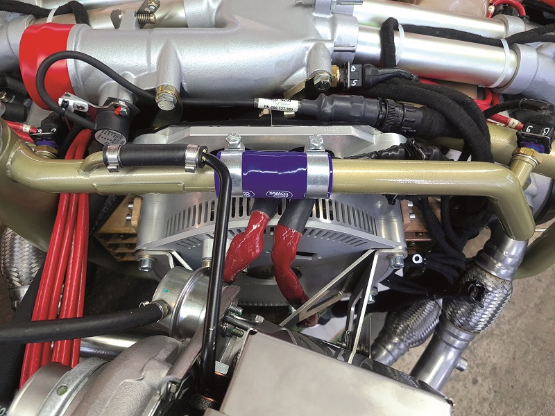
Around 70% is dissipated at the cylinder heads through a liquid-cooling system, with the rest being dissipated through two direct-air cooling systems: one for the cylinders, the other for the generator.
A mixture of water and ethylene glycol (50% glycol, for frost and corrosion protection) is pumped through 25 mm pipes into the cylinder heads at a rate of about 0.1 m3/minute when the engine is running at 3000 rpm. The pump is belt-driven by the crankshaft, and a tensioning adjustment arm and jockey wheel sustain the tension on the drive belt.
After encircling the combustion chambers, including the spark plugs and exhaust valves, the water exits the heads through tubes opposite the inlet pipes and on to a collector, a thermostat and then a radiator before returning to the pump.
The standard-issue radiator is sized for an anticipated airspeed of 40 m/s (144 kph) during climb and a temperature differential of 60 °C between the liquid coolant entering the radiator and the ambient air. A water-glycol temperature of 110 °C is the maximum tolerable.
However, the radiator can also be resized to suit each end-user’s climb airspeed, their air inlet and outlet designs, and what positions are available for mounting it. For instance, a smaller radiator can be used if the UAV flies much faster than 144 kph during ascent.
“The liquid cooling as well as the cylinder heads are optimised for the pressure of the water-glycol mix, and are unique to our 2400 series engines,” Simmerkuss says. “They were developed specifically to enable the higher power output of this engine, and to prevent the kind of wear that cylinders and cylinder heads can suffer without a rigorous design of the cooling system. Most of our other engines use only air cooling.”
Ram-air cooling for the cylinders requires only 25% of the airflow necessary for cooling a conventional air-cooled engine, although some additional pressure to around 1.2 bar is ideal. That is a guide value: the important end result is that air flows over the cylinders at roughly 0.2 m3/s, or 0.17 kg/s. To enable that, a pair of inlets made from fibreglass-reinforced plastic composite sit on top of the engine and connect to ducts that direct the airflow to the cylinders’ surfaces.
“We could have designed the cylinders such that the water flowed from the heads down into the cylinder walls, but this would have meant excessive cooling relative to the design and manufacturing changes needed – air is sufficient for the cylinders,” Simmerkuss adds.
“Ideally, the engine should be used with a tractor propeller, as airflow coming from the prop will directly enter the two inlets and go towards the cylinder fins, and that tends to provide sufficient air pressure for cooling the cylinders. But a pusher configuration is also no problem, so long as sufficient cooling air can be directed to the air inlets.”
In addition to the two ducts that send air coolant to the four cylinders, a third duct directs air to the generator. Once the high-pressure air has flowed through the stator and the cylinder fins, it returns to a pressure closer to ambient levels and exits through an outlet in the engine cowling.
The L 550 EFG
In addition to supplying the L 2400 DX, Limbach has continued providing the L 275 EF and its larger variant the L 550 EF, the newest version of which is the L 550 EFG.
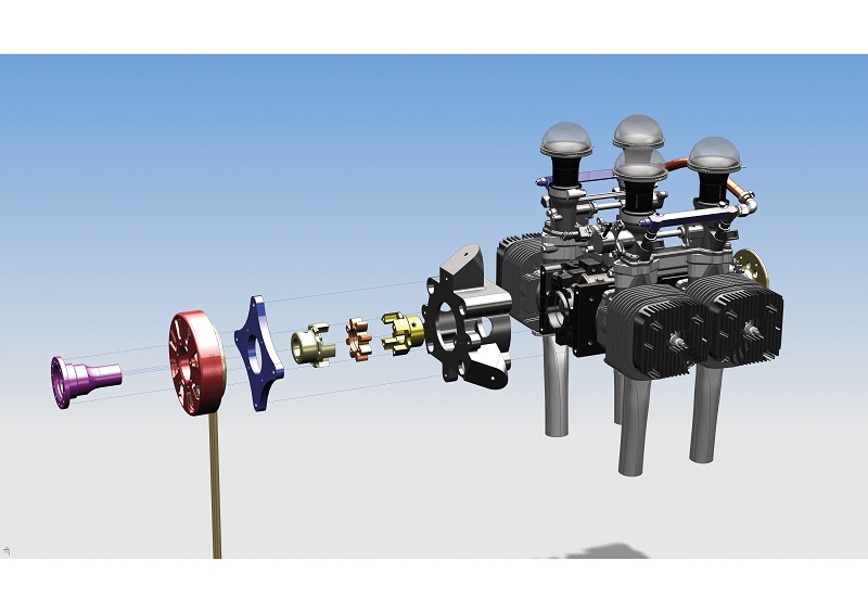
In the company’s words, the L 550 EFG – and its standard-issue version without a gearbox, the L 550 EF – features effectively “two of everything” that the L 275 EF has, aside from a couple of innovations.
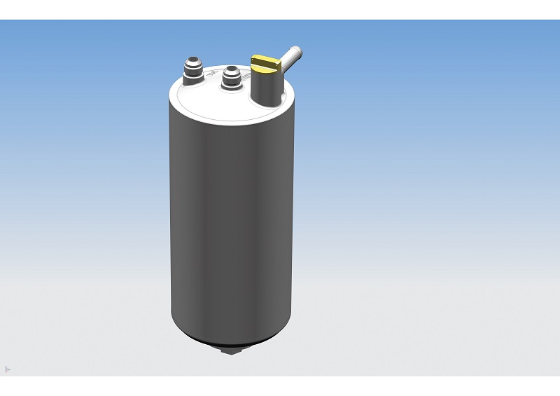
Starter/generator
One is that Limbach has begun integrating starter/generators from ePropelled onto both engines. The L 550 EFG now has an ePropelled SG3000, which generates a peak power of up to 4 kW, although that is available for only 3 minutes as a boost, and a more sustainable 2.5-3.5 kW is available at the engine’s top speed. It measures 127 x 40 mm and weighs 1132 g, including its bearing, winding leads and thermal sensor. The last of these is optional, for users who want to monitor or record their stator winding temperatures.
The 18 kW L 275 EF meanwhile will integrate an SG750, which can sustain peaks of 1 kW for 3 minutes and produces 800 W over 50 V AC at 7500 rpm. It measures 101 mm in diameter and 28.6 mm tall, and weighs 440 g with all ancillaries.
Both generators are brushless, permanent magnet, three-phase AC types, optimised for power density and for directly mounting on their engines’ crankshafts. They have hand-wound and resin-impregnated stator windings.
“These systems appealed to us not just because of their usefulness as range extenders and for powering heavy-duty payloads like Lidars, but also because of that power boost ability,” Simmerkuss comments. “You can put battery energy into the starter/generator and have it function as a motor, to add potentially up to 4 kW of extra shaft power to the engine.
“We’ve planned further testing to see how much boost can be added and for how long, as well as the impact it could have on the TBO of either engine, as it would mean running the crank speed higher than our current specified safe limits. But that capability is important, for instance if you need to suddenly climb quickly, because say of sudden obstacles during flight.
“On top of that, having a reasonably high-power generator on the engine shaft means it’s possible to switch temporarily to 100% electric propulsion. If the propeller is driven entirely by the motor/generator, the noise output goes down quite a bit, which is handy for geospatial surveyors or delivery UAVs whose operators don’t want to disturb populated areas.”
The generators feature ePropelled’s active air-cooling technology: ducts on the housing enable air to be drawn into the stator by way of the rotor acting as a compressor. This and the stator winding temperature sensors are cited by Simmerkuss and Schmieder as major benefits.
Installing the SG3000 first involved some customisation of the generator’s rotor so that it could fit on the engine’s crank journal and so that both systems could handle each other’s rotational movements. That was achieved largely by using an adapter shaft and a rotary vibration damper, as well as the existing connections on the 550’s crank.
Limbach’s engineers also made an adapter plate for fastening the housing to the engine. The generator’s housing was then screwed to the adapter plate.
Limbach also reports that ePropelled’s iPS (intelligent Power System) and EES (Electronic Engine Starter) module have been installed on the L 550 EFG.
The iPS enables consistent transmission, conversion and monitoring of electrical power to onboard systems such as avionics, payloads and batteries. The EES provides the engine starting function while also being able to restart the engine during flight independently of technicians or other crew members, if for instance a fault occurs or the engine has been stopped for the aforementioned noise-related reasons.
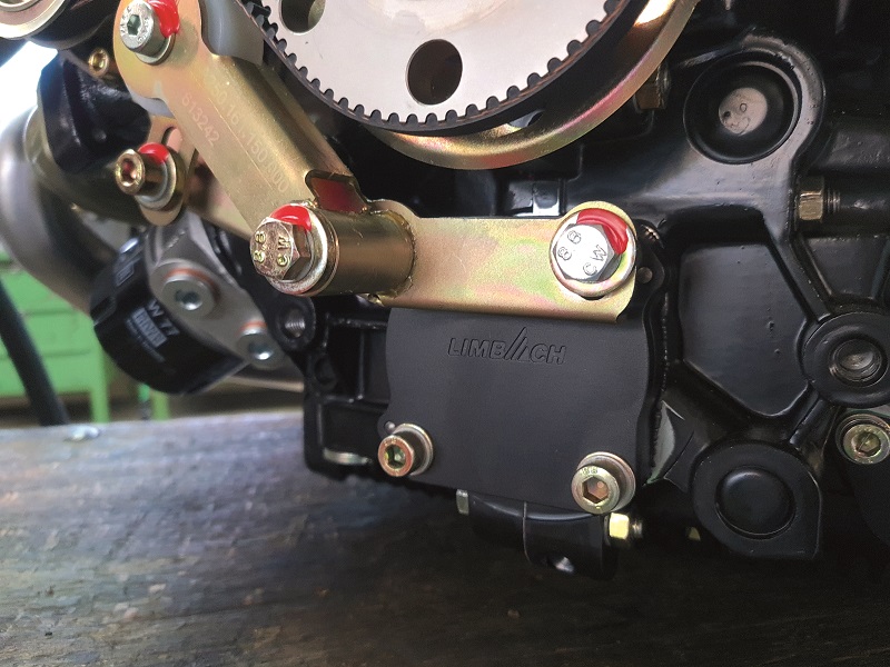
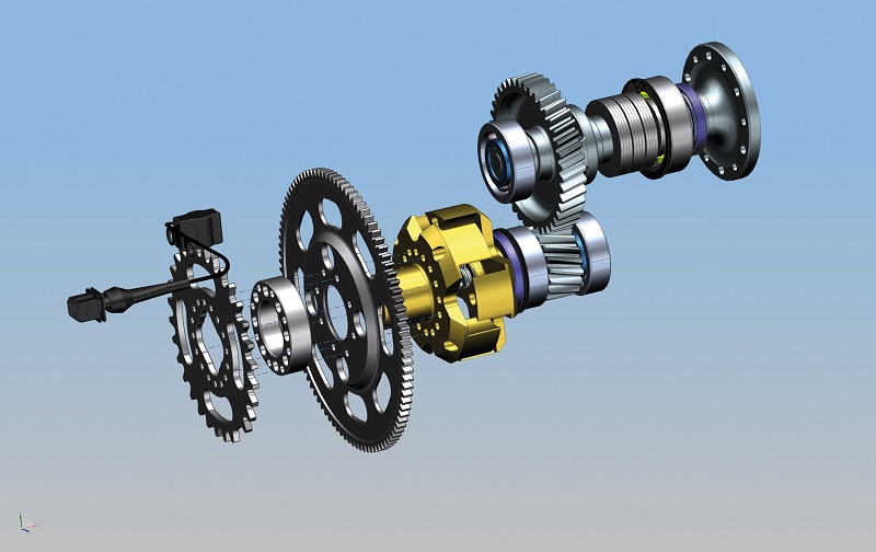
Single-speed gearbox
The L 550 EFG’s new gearbox adds roughly 13 kg of weight, for a total mass of 28 kg. In exchange, the end-user gets a torque output at the transmission output shaft and propeller mount of about 96 Nm. That comes through the transmission approximately halving the output shaft’s speed from the crankshaft’s 7500 rpm maximum continuous rate to 3378 rpm. The gearbox’s efficiency is estimated at around 93%.
“Naturally it will be a case-by-case matter that UAV manufacturers will need to decide on, if the higher efficiency for their propeller is worth the extra weight, or if they want a lighter engine and a less efficient prop,” Simmerkuss says.
An earlier design of this gearbox was developed in the 1990s for one of Limbach’s carburetted two-strokes. In response to customer requests it has been redesigned and adapted for the L 550 EF.
The design features a mounting plate at the rear, through which the L 550’s output shaft is inserted and bonded to a coupling made of high-strength aluminium. Within this initial stage of the gearbox is an iron trigger wheel that serves as an rpm sensor, a toothed gear for engine starting, and an aluminium spacer ring between the two.
Simmerkuss adds that in due course the starter gear will be rendered obsolete by the ePropelled starter/generator, although some customers have indicated that they might opt for both starting systems for redundancy.
Forward of the coupling, between two ball bearings, sits a small steel gear with 18 angle-cut teeth; these are quieter than straight-cut gears, with negligible increases in axial loads and mechanical stresses. That gear engages with a 40-toothed larger gear, giving a reduction ratio of 2.22:1.
“We use 6305 and 6205 standard bearings, and before the first bearing we have a sealing ring,” Simmerkuss says. “That creates a closed chamber for the transmission output, which has enough oil spilling around to keep the gears and bearings lubricated for the lifetime of the gearbox.”
Ahead of the large driven gear is a dog clutch. The output shaft extends forward from there, and on it is fitted a series of springs to mitigate the impact and torsional stress on the gearbox caused by a prop strike for example.
Further development of the gearbox is planned, particularly tests of different housing materials to identify where weight can be removed without losing too much ruggedness.
Future plans
Limbach plans to continue adopting new technologies for better torque density and hybridisation. In addition to the improvements set out here, it also plans to adapt ePropelled’s generators to the L 2400 series, to allow heavy UAV makers to get the high horsepower and electrical power they need.
“We also want to offer a wider range of starter/generator options, such as 6 and 10 kW systems alongside the 7 kW unit, for each aircraft’s weight and power requirements,” Simmerkuss adds.
Limbach is also developing a new ECU for its two-strokes to enable throttle servo control and data monitoring over CAN, which it says is a 12 V system but will also be available for 24 V using an integrated DC-DC converter to ensure the injectors still get 12 V.
It will also have several self-programmable analogue and digital inputs and outputs for additional sensors and other electronic devices, as well as a smaller and lighter housing. The ECU, along with new engine mounts and vibration dampers for the L 275s and L 550s, is due to be available this summer.
In a final disclosure, Limbach says improvements in its four-stroke and two-stroke exhaust systems are in the works.
Anatomy
The crankcase of the L 2400 is cast from aluminium and constructed in two halves, with the split running vertically down the length of the block, and eight studs located about the cylinders serving to link the two halves together (along with the cylinders, heads and covers), which are fastened using 8.4 mm washers and M8 nuts.
The crankshaft is forged as a single piece from steel for high strength and low porosity. The shaft mounts to the crankcase on four plain bearings, on journals measuring 22.9 mm, 25.9 mm and 26.2 mm in width (in order from front to back). The big-end journal meanwhile is 24.5 mm wide and 58.5 mm in diameter. The maximum diameter of the crankshaft is 142 mm and its length is 374 mm.
A spur gear fits on the crankshaft for driving the camshaft, and has a spacer ring and a circlip. A shaft seal ring and a spacer ring sit further forward to hold the front main bearing in place, with two washers and another shaft seal ring holding the rear main bearing.
The con rods are two-piece systems, forged as monolithic items before being cracked into separate parts. Two nuts hold each big end together, with a two-piece plain bearing inside each one.

Material and coating details on the piston are largely proprietary. Each is 97 mm in diameter and has three rings in the standard compression, oil control and oil scraper arrangement, with a wrist pin and two circlips connecting each piston with the small end of its con rod.
The cylinders are machined from aluminium, coated internally with nickel silicon carbide, and mounted to the crankcase with a metal gasket. The heads mount with a metallic, PTFE-coated gasket to the cylinders, on top of which the valve covers are fastened using a metal clamp and a cork gasket.
As indicated, the camshaft runs mechanically off the crankshaft, using a gear on its back and the aforementioned spur gear. It is made from steel, sits in a chamber below the crankshaft (held in place by three plain bearings) and has four cam lobes, each responsible for a valve on either opposing cylinder.
Each lobe acts on a pushrod via a tappet, which is fastened using a sealing ring to a protective tubing around each pushrod. The pushrod actuates a rocker arm that sits on a rocker shaft and is held by two washers and a spring ring. An M8 nut and screw fix the valve key to the rocker arm, to press and lift the valve via its spring and retainer. The inlet valves are 41 mm in diameter, and the exhaust valves are 35 mm.
Specifications
L 2400 DX
- Four-stroke
- Four-cylinder boxer
- 98 or 95 octane gasoline
- Turbocharged
- Air, water and oil-cooled
- Bore: 97 mm
- Stroke: 82 mm
- Displacement: 2424 cc
- Maximum power (for take-off): 118 kW at 3000 rpm
- Maximum continuous power: 103 kW at 3000 rpm
- Maximum speed: 3100 rpm (maximum usable is 3000 rpm)
- Fuel consumption:255 g/kWh at WOT
L 550 EFG
- Two-stroke
- Four-cylinder boxer
- 90 octane gasoline
- Naturally aspirated
- Air-cooled
- Bore: 66 mm
- Stroke: 40 mm
- Displacement: 548 cc
- Maximum power: 36.77 kW at 7000 rpm
Some key suppliers
L 2400 DX
- Spark plugs: NGK
- Fuel injectors: IWP
- Electric fuel pumps: Pierburg
- Crankshaft: in-house
- Crank pins: in-house
- Con rods: in-house
- Engine management system: Trijekt (modified in-house)
- Starter: Magneton
- Generator: Brise
- Turbocharger: in-house
L 550 EFG
- Spark plugs: Bosch
- Fuel injectors: Magneti Marelli
- Crankshaft: in-house
- Crank pins: in-house
- Con rods: in-house
- Main bearings: SKF
- Oil seals: various
- Engine management system: Trijekt
- Generator: ePropelled
UPCOMING EVENTS


