


FCT Sweden Lamina fuel cell
(All images: FCT Sweden)
Build me up
This Swedish company’s planar fuel cells are unlocking new heights of design flexibility, production scalability and return on investment for vehicle integrators seeking clean, quiet and reliable electric power. Rory Jackson investigates
The world of uncrewed systems is, in many ways, a critical beachhead market for hydrogen power solutions. Despite their detractors, we have unpacked major success stories such as Canada’s Cellula Robotics (Issue 30) and Zepher Flight Labs (now part of Heven AeroTech – Issue 36), who started out on hydrogen fuel cells and – half a decade later – have continued growing and serving both defence and commercial customers while openly using the universe’s most abundant element as their primary energy medium.
One may yet argue that each uncrewed system exists in its own localised, specific niche, and thus is not an optimal blueprint for how hydrogen fuel cells might achieve more widespread success. But blueprints for such are not hard to find: Toyota, for instance, went against the tide by pouring 20–30 years of R&D into designing a fuel cell that could be manufactured cost-effectively, scaled via its existing automotive production lines and utilised as a drop-in replacement for ICE range extenders in a wide range of vehicles beyond the Mirai. The OEM is now poised to release its third-generation fuel cell by the end of 2026, with dramatic increases in fuel efficiency and reduced manufacturing cost, buoyed by R&D from its labs to its H2-powered motorsport entries.
Such ingredients are now propelling a new fuel cell approach on the opposite side of the planet, with Fuel Cell Technology (FCT) Sweden having recently stepped into the limelight with its unique Lamina solution.
The roots of the company’s technology were planted at KTH (Kungliga Tekniska Högskolan), Stockholm’s Royal Institute of Technology, in 2005, by researchers driven to create a form of power and heat generation so flexibly integrated that it could be mounted anywhere, not to mention being highly cost-efficient, in the hopes that these properties would make it highly accessible and adoptable to developing countries and underprivileged communities.
“To make a power system that could fit anywhere, it quickly dawned that it had to have as few ancillary systems around it as possible. Initial concepts leaned more towards some kind of power-generating sticker, which wasn’t so feasible, but Lamina today is as stripped-back a fuel cell as one can find, principally needing only access to hydrogen and air, and the latter needn’t be an active air flow,” explains Katrin Kortsdottir, fuel cell development engineer at FCT Sweden.
“For automotive performance, active air flow is needed, but it doesn’t need a fan – just ambient air flow from forward movement is enough, with marginal pressure drop at most.”
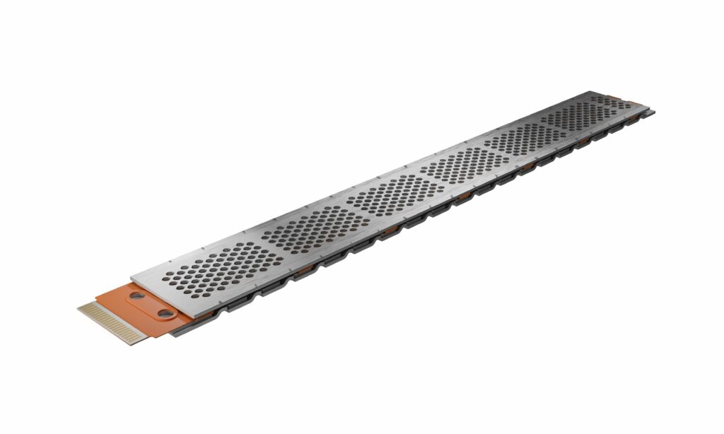
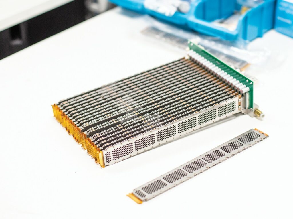
While most solutions we investigate in these features are fully built systems, the Lamina LS-10 is just a singular fuel cell plate – a planar fuel cell, as correctly termed – 23.8 cm in length, 2.7 cm wide and 0.38 cm tall, weighing 90 g. That single unit outputs 10 W nominally, up to a 12 W peak, over an operating voltage of 3–4.5 V DC.
While achieving standard open cathode PEM (Proton Exchange Membrane) fuel cell performance on paper – with a 0.6 A/cm2 current density – when one realises that multiple Lamina units can be strung together as long, thin building blocks in any number of combinations, the actual, unique value of FCT Sweden’s invention starts to reveal itself.
“The form factor means we’re not a discrete stack, coming in fixed bricks like other fuel cells. We’ve designed a planar assembly, which is easily volume-manufactured and assembled to whatever geometric arrangement the end user needs, including making curved Lamina cells with no performance difference,” says CTO Sebastian Weber.
“It also avoids the need for auxiliary systems because of how we’ve engineered our electronics, on top of using no moving components, meaning it’s an especially thrifty and simple electricity producer, and so it’s still suitable for many applications in the developing world, as the original researchers wanted.”
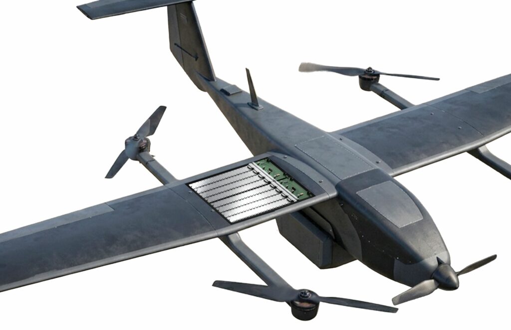
Hence, we investigate the 10 W Lamina LS-10 ‘micro’ fuel cell because it poses the building block of a larger, fully realised system. Whether using flat Laminas or curved ones, UAV manufacturers choosing Lamina can replace existing portions of aerostructures – such as wings, fuselages and tailplanes – with Laminas, not only atop as with solar cells but also underneath, thereby trading inert structural mass for (stainless steel) plates that actively supply power.
By then cutting back on onboard battery energy in exchange for hydrogen gas – the latter being over 300 times more energy dense than the former – and storing the latter in modern, carbon-fibre tanks, the weight-saving realised through using FCT’s solution becomes calculable (although it will depend heavily on use-case: a 15 kg fixed-wing battery-electric UAV might cut half its powertrain weight by designing an alternate version around Lamina).
Fuel cell anatomy
It was from 2008 that many of the patents behind Lamina’s core technologies were first being filed and granted, including unique approaches to cell monitoring and clamping key to the fuel cell’s 3000 h lifespan (and performance stability over the interim), with other patents granted more recently having encouraged FCT to take the step of unveiling its solutions publicly.
“But key barriers to success back then included poor availability of hydrogen in a form factor useful for us, and the tendency of capital investment to give priority to large, +10 kW technologies. Both of those have improved in recent years, however, opening the way for hydrogen in smaller applications like drones, robotics, small machinery, combined heat and power for homes and others that need simplicity and cost-effectiveness over sheer mass,” Weber says.
“Other manufacturers have also been limited by the difficulty in customising PEM fuel cells. If they want to manufacture at scale, they have to lock their production lines into ‘this’ specific form factor, ‘that’ particular large cube as a minimum purchasable unit, whereas our Lamina scales more like a battery cell in serial and parallel configurations. We can place them together or line them up to suit all kinds of airframe shapes and volumes, with only discreet electric and hydrogen connections running between.”
The membrane electrode assembly (MEA) layers of the Lamina PEM are conventional, with a central PEM coated on either side with the catalyst powder blend key to the electrochemical reaction by which electrons are extracted from hydrogen to form current (with water formed as a by-product).

“The catalyst-coated membrane is then sandwiched within two gas diffusion layers [GDLs], which in turn are placed in sealings, and on top of that is an additional sandwich – namely, our flexible PCB, or what we call our ‘FlexFoil’, which we’ll expand on later,” Kortsdottir explains.
“There’s little more beyond that; just the top and base plates made of stainless steel and a hydrogen gas channel running inside said base plate.”
The core membrane is based on conventional, commercially available Nafion-type materials as per other PEM fuel cells we have featured, and thus the same kind of materials as mass-manufactured for heavy-duty vehicular or machine applications.
“And our catalyst uses platinum nanoparticles, dispersed on high surface carbon, as is commercially standard,” Kortsdottir continues.
The gas diffusion layer, meanwhile, is composed first of a macro-structural layer – typically either woven or paper carbon fibres – which is then paired with a micro-porous layer, in most cases carbon particles mixed with PTFE to achieve hydrophobic properties, that being a vital mechanism for transporting the by-product water out of the fuel cell.
While FCT Sweden optimises its GDL selection to allow stability at most operating conditions, it does have the possibility of customising GDL selection for specific conditions (wet conditions, for instance, call for a more open structure that can more easily transport water out).
“Choosing the right GDL and other PEM fuel cell materials is crucial to fuel cell performance. This is why we work closely with suppliers to optimise the choice of these to fit our system.” Weber notes. “Having more or less no balance of plant [BoP] makes the GDL selection an integral part of optimising the Lamina performance for the applications.”
The standard-issue Lamina uses a GDL more optimised for dry conditions because its highly open architecture – being both an open-cathode fuel cell and having an open-ended anode design (further discussed below) – lends itself toward easy evacuation of water as a basic principle, with the high internal temperature conventional of PEM fuel cells enabling persistently dry conditions where needed inside Lamina.
One notable absence among these layers, however, is bipolar plates (BPPs), which our readers may recall as (normally) being vital to the delivery and routing of hydrogen and oxygen across either face of each individual PEM piece, on top of functioning as the current collectors.
“Our FlexFoil is key to that. Normally, PEM cells stacked on top of each other are electrically connected using bipolar plates – but, of course, Lamina was always meant to work without needing to be stacked like that,” Kortsdottir says.
Hence, FCT needed some other way to connect the cells. While it has tried other approaches in the past, it now uses a flexible PCB from circuitry multinational NCAB Group Sweden AB.
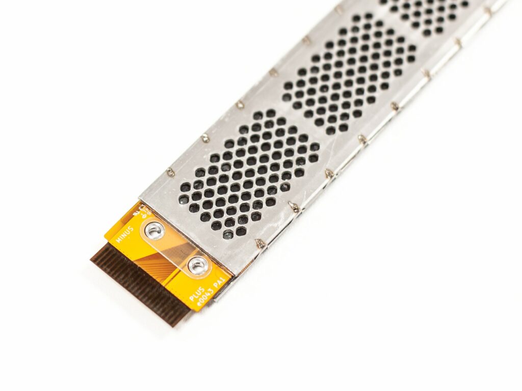
“Each Lamina unit’s flex PCB is visible, protruding at one end where it is folded to connect the cathode to the anode current collector, and that’s how we’re able to connect multiple cells in series with very little footprint, which is otherwise a challenge in planar fuel cell approaches,” Kortsdottir explains, pointing out the flex PCB’s orange, translucent end-tab for us with a held Lamina unit.
On top of that, the flex PCB functions as the current collector and enables the reactant air in the open cathode design to reach the cell. The top plate is also designed to accommodate the reactant air access, preventing FCT from needing to invest R&D into the flow- and hydrodynamics of BPPs.
“Using these two easily available components as inputs is a key part of how we’re able to produce the cells in high volume and keep extremely low cost levels,” Weber notes. “And having a PCB running inside of each cell gives us unique opportunities in condition monitoring, control and auxiliary system functionality, which we’ll talk about later.
“That dual purpose demanded of BPPs is why there are so many companies toiling to develop and specialise BPP technology, tinkering with their flow fields, materials and other properties. But as our cells work in a planar arrangement, rather than being tightly stacked atop each other, we don’t need BPPs tightly separating one cell’s anode from another’s cathode, and it also means we can use one FlexFoil per cell, folding from one side over the other.”
Although flexible circuit boards are now widely available products, FCT lauds NCAB as being especially helpful and easy to work with as a supplier, as well as exhibiting high production yields with consistent quality control levels – crucial ingredients to ensuring the Lamina cells always incorporate flexible PCBs manufactured to exact specifications and at low prices.
Manufacturing Lamina
While scale manufacturing has been the Achilles’ heel for many fuel cells in the past (save for the likes of Toyota and Intelligent Energy), several factors contribute to Lamina’s easy producibility, on top of using components available in bulk such as flexible PCBs, stainless steel plates and standard PEM components.
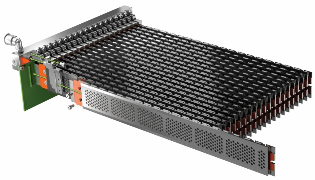
Production of a Lamina unit starts with a base plate, which is stamped into the correct form factor. Then, a fixture is used to enable exact placement of the FlexFoil, followed by the PEM fuel cell layers, forming the sandwich of GDLs about the core membrane, before the FlexFoil is folded over the top, and the cathode-side top plate is mounted as the final part.
“All of this, including the sandwich of FlexFoil, GDL and MEA, is assembled in an automated process that in high-volume production uses ‘pick-and-place’ robotic machinery,” Weber says.

“The front and base plate and gas channel are stamped in parallel and applied to the sandwich before we use laser spot welding to form our clamping system, which secures the plates together with precise compression – with significant intellectual property rights around how we form it consistently without ever over- or under-compressing – but, centrally, the laser welding is another key part of how we enable our long-running goal of very efficient, high-volume production.”
The outer plates themselves are sourced from Nippon Steel (which FCT notes is renowned for its high production quality), while the layer placement followed by the plate stamping and welding is currently performed by GEC in Thailand.
“The plates don’t necessarily have to be stainless steel, but we do need them to be quite stiff. Stainless steel is widely available, simple to manufacture and work with, and has good thermal properties for the cooling requirements of Lamina’s high surface-to-volume ratio – but we can change the plates to other materials such as aluminium, depending on customer-specific factors such as environment, cost, weight and so on,” Weber notes.
“But stainless is also highly manufacturable, from cutting through to laser spot welding, and it works well with our patented clamping approach. So, from that perspective, it has a lot of helpful qualities for production cost and scalability, which will make it worth keeping in a lot of applications.”
All in all, a single Lamina unit can be assembled and welded by robots occupying a minimalistic floor space, and Weber adds that even the prototyping space formerly used to build Laminas by hand was not a large space; hence, its production can be scaled in a gradual, cost-effective, unitary manner depending on project- or region-specific demand.
“We took a lot of inspiration and competencies from the personal electronic device industry when seeking to design Lamina for straightforward manufacturing. That space heavily uses sanitised trays and robotic solutions that can pick-and-place more than one component, as do we,” he adds.
Clamping
Optimising clamping is vital in PEM fuel cells because the porous internal layers can collapse (blocking air and hydrogen flows) if over-compressed, and contact resistance will shoot up (inducing high heat and power inefficiency) if under-compressed.
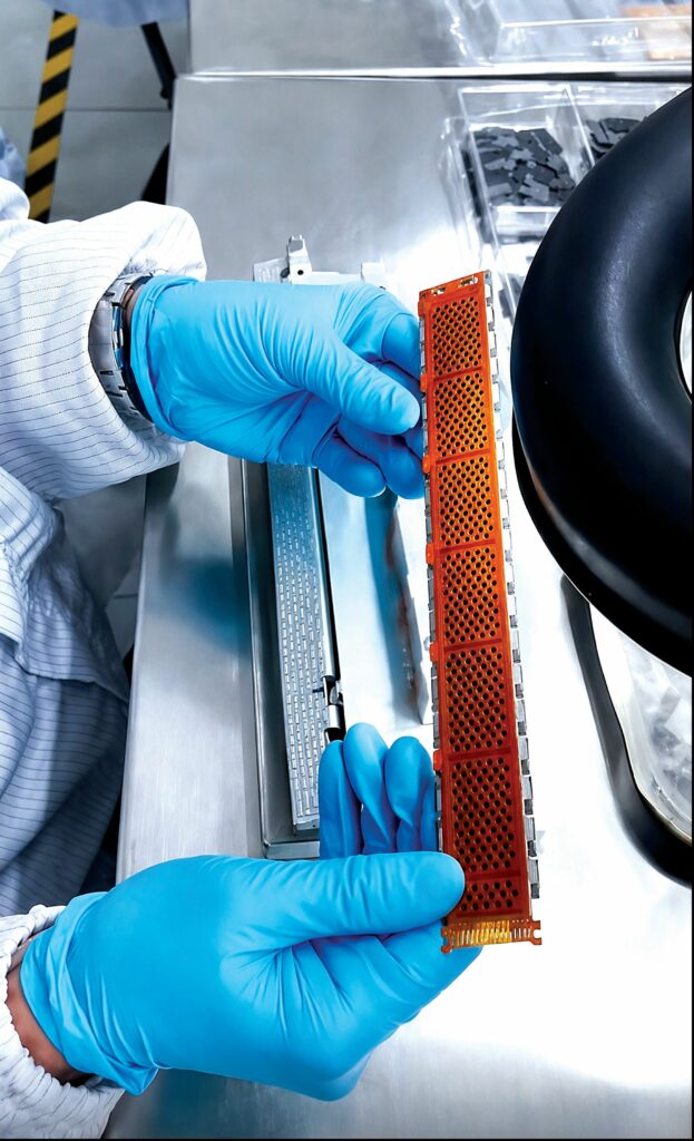
“It’s a very delicate balance to strike, but in Lamina, one can see along the narrow sides that we have a series of symmetrical ‘flags’ or ‘tongues’ in the stainless steel, the geometries of which are calculated such that we’re really exerting the optimal amount of force onto the stack once they’ve been welded – not too little, not too much,” Kortsdottir explains.
The flags are cut out from the metal plates during production, and then welded to connect the top and base plates such that they mechanically function as springs. As a result, the same compression force or clamping pressure is exerted even amidst the slight tolerancing differences that can occur during manufacturing, enabling FCT to use high-volume machinery or contract production facilities where quality control (although certified) might be microscopically inconsistent.
“This approach works particularly well with the stainless steel plates we use as standard because the elastic modulus of stainless is very favourable in this set-up,” Weber adds.
It also notably avoids using traditional approaches such as highly torqued and heavy bolts running the length of stacks (which would be prohibitively heavy if deployed across the many MEAs of a planar fuel cell arrangement) or industrial rubber bands that can strike customers as an insecure or vulnerable means of compression.
Cell monitoring
Another critical innovation of FCT’s toward the long-term stability, reliability and efficiency of its fuel cells stem from what it calls its ‘Sensor Cell’.
The Sensor Cell is visible at the far end of each Lamina MEA, at the opposite end from the FlexFoil tab. It is an additional, smaller PEM fuel cell unit, identical in composition to the other six visible by their separate air intakes across the length of the Lamina assembly, but about a quarter their size.
“Hydrogen gas enters each Lamina from the end with the FlexFoil tab, passing through a gas channel into each separate cell in the Lamina unit before entering the Sensor Cell, and thereafter it would exit if there happens to be unregulated and any excess hydrogen,” Kortsdottir says.
Unlike the other six cells, however, which are all connected via the FlexFoil’s current collector, the Sensor Cell connects instead to detailed condition monitoring systems and is operated in a passive mode. The signal from the sensor cell allows the main current to be controlled such that exactly the right amount of hydrogen is used in the Lamina, and no excess hydrogen is exhausted. This enables the fuel cell control unit (FCCU) – in this case, FCT Sweden’s ‘Master Computer’ – to closely track key performance and health parameters of the Sensor Cell and the system.

Readers familiar with our past investigations of PEM fuel cells (or other technical documentations of such solutions) may recall that closed-loop, in-depth monitoring of hydrogen fuel cells is challenging. A stack may comprise dozens or hundreds of individual cells, and to collect, aggregate and analyse data from all of them drives up expenses and computational burdens per stack in terms of data acquisition, algorithm and control systems.
“But by having this smaller, extra cell just for monitoring purposes, which has an identical membrane, catalyst coating and GDL to the others except in terms of length, we can more precisely and richly track the load and other parameters of that cell via its signal feedback,” Weber explains.
“By sensing that load over a small buffer, we can measure how the application is operating, and use that to automatically regulate the load demanded of the cells – using the Sensor Cell to ensure the right level of hydrogen – with a more right-sized, efficient data acquisition and management system allowing for optimised performance.”
Advantages of using this one extra micro-cell as a control, over simply using the sixth identical cell in the stack, gives conditions less prone to excess air ingress (which could cause corrosion in the last cell otherwise), and the ability to design the Sensor Cell such that it can signal whether there is too much or not enough H2 gas in the fuel cell assembly (whereas using the last identical or ordinary cell would limit Lamina to detecting only when there is too little H2).
As a result, no excess H2 leaks out, meaning no risk of dangerous gas build-ups in or at the fuel cell application that might merit extra safety release valves, and reducing inefficiencies in hydrogen utilisation. The company adds that developing and including Sensor Cells in each Lamina adds insignificant, marginal costs per unit, marking it as a significant long-term ROI driver for the fuel cell.
Weber also notes additional intelligence in the Master Computer FCCU, which is key to the outer Lamina common hydrogen regulation loop from the input end. A software-defined gas regulation loop controls the metering of hydrogen flow into the cells, including the capacity to dial back fuel input if the Sensor Cell indicates excess gas flow or pressure.
In summary, the Sensor Cell, outer hydrogen loop and the load sensing facilitate a clean, simple and straightforward system to secure the correct power to the load without risking reactant starvation.
Further information on FCT’s IP on gas regulation must remain under wraps until its patent on the technology is granted (the company does, however, divulge that it forgoes traditional pressure regulators because these are excessively large components for Lamina’s planar form factor – as one may have already assumed).
Weber also discusses with us how FCT ensures that load management is kept computationally efficient and low-latency. “A fuel cell operates most reliably over the long term if you’re not constantly changing its operating point, even though a lot of fuel cells do that in the course of gas regulation. But to balance the output power, one typically adds an accumulator, like a battery, an electrolyte capacitor or a supercapacitor.
“The important part of our IP there, is – as previously mentioned – that we track the associated buffer’s condition in order to regulate how Lamina operates. In contrast to other fuel cells, where they need to constantly communicate with the load, our system is essentially automated. We track the buffer’s energy and power levels, and regulate just when necessary to make sure we’re working well enough for the buffer. That removes a lot of the complexity from how fuel cells are typically operated.”
Open-ended anode
As discussed, hydrogen passing through Lamina’s gas channel will escape through the outlet if not consumed at the anode. This is the essence of the open-ended anode design quality of Lamina, something at odds with other fuel cells we have featured in which there was always either a seal or valve to hinder egress of unconsumed hydrogen gas.
“The more standard approach, which you might call a closed-ended or dead-ended anode, is more prone to relying on over-pressurised hydrogen gas to ensure fuel consumption for the load,” Weber explains.
“The challenge with that is the likelihood of over-pressurising the inside of the cell, which especially creates mechanical stress on the cathode side, and that creates a need to compensate by over-pressurising the cathode with oxygen or ambient air, to balance things out and prevent mechanical stresses which could shorten the cell’s lifetime.”
Kortsdottir also points out that dead-ended anodes often rely on purging valves to evacuate unreacted hydrogen gas as well as by-product water. However, purge valves introduce threats to efficiency such as insufficient purging during high loads for maintaining consistent and optimal power output, or excessive purging during low loads such that hydrogen gas is pointlessly dumped overboard before the fuel cell has a chance to consume it.
“By going with an open-ended anode, we don’t need a purge valve and we keep Lamina as a really simple system, avoiding the mechanical and fuel-efficiency hazards that valves – like other mechanical BoP components – would bring into our fuel cell,” she summarises.
“And as we’ve explained, Sensor Cell is our innovation by which we make sure that open architecture doesn’t leak or waste hydrogen; we didn’t invent open-ended anodes, but we have put R&D into ensuring that the concept works.”
Open cathode
For those needing a reminder, open-cathode PEM fuel cells utilise the same air as electrochemical reactant as they do for cooling. Ambient air flows into the cell stack, typically forced by a fan or compressor to ensure sufficient pull through the otherwise-inaccessible channels running deep inside the stack. There, it dissipates heat, first as air and then afterwards as water, which forms upon the air’s O2 molecules bonding with the hydrogen ions created once the H2 molecules’ electrons are knocked free by the platinum–carbon catalyst, the latter then being drawn into the fuel cell’s BPPs as current.
Lamina avoids needing fans because its cathode channels face open air (per their planar arrangements), instead of being hidden or trapped away under other components – bipolar plates – as per conventional stack-based designs.
The air-breathing (or free-breathing) nature of Lamina’s cathode side is visible via a prominent diamond-like pattern on its steel grill, and that pattern is key to achieving uniform clamping pressure across the cell’s air-breathing surface following FCT’s patented clamping approach.
“That’s a key advantage of the open-cathode approach, especially for our minimalist design. It really helps strip back the fuel cell to passive components rather than needing any active, moving components that could fail or take up extra space,” Weber says.
Cited disadvantages of the open-cathode topology include the risk of flooding due to poor fluid flow evacuation inside the stack, and losses in both current and longevity due to the lack of active humidification as compared with closed-cathode fuel cells (that then compels open-cathode PEM fuel cells to perform current pulsing to rejuvenate their stacks’ humidity, which requires disconnecting the power to load – thereby greatly impairing performance stability).
Naturally, Lamina’s free-breathing design enables by-product water to dissipate freely, with no BPPs to trap it in place, preventing flooding. As to the humidity maintenance, FCT Sweden’s control architecture (discussed below) is a critical enabler – the company also has proprietary means by which it avoids the need for current pulsing. The latter is another patent-pending innovation, although the company pledges to explain it once the patent is granted and the technology protected.
“We also have a thin filtering component, which helps keep contaminants out and maintains a controlled operating environment for the fuel cell. If you drop it in mud, that’s another story, but in all operating conditions we or our trial customers have tested, it’s surprisingly consistent and effective,” Kortsdottir adds.

Extra filtering may be added, depending on the environment. FCT has publicly reported working with automated guided vehicles in factory environments, handling not only the repeated stop-and-start (including cold starting)-prone nature of the application but also the unexpectedly dirty conditions of otherwise ISO-certified production facilities.
“Active intake with filtering can actually function as a vacuum cleaner in such environments, just sucking up dirt and really working hard to pull it into your fuel cells or electronics, but we have different kinds of passive or active filtering that we can upgrade or downgrade for each use-case. Certainly, military environments with different chemical vapours in the air would be straightforward to select filters for, so long as we’re given the right information to design accordingly.”
To illustrate the passive, self-sustaining qualities of its technology, as well as its capacity to function in a vehicle that periodically halts instead of always moving forwards through the air (unlike STOL fixed-wing UAVs), FCT has engaged with a project replacing the large battery pack on a mountain bike’s downtube frame, with an assembly integrating 12 Laminas enclosing a small hydrogen gas tank (along with a much reduced buffer battery).
“As well as being a monolithic set-up like the battery pack it replaced, that showed we could use the available space extremely efficiently, even including the cylinder, in a complex and very volumetrically dense implementation,” Weber continues.
“And instead of focusing on producing as much as necessary to charge the buffer battery, we just had to engineer the system to produce as much as we could for the temperatures it’d work at. When the bike was stopped, the regulating algorithm would keep fuel consumption and power output low to prevent overheating the fuel cells.
“But when the cyclist started moving, that was when the Laminas could really max out, because the passive air flow at their speeds provided more than enough cooling and intake air pressure. It all worked really well, producing enough energy to aid uphill climbs before recharging plentifully on downhill slopes, and so we’ve delivered the design to the customer as a prototype [as of writing].”
One can note that the mountain bike implementation suggests potential for Laminas in multi-rotor UAV applications, being another use-case with transients between high energy consumption (whether in a bike going uphill or in a multi-rotor in hover or VTOL mode) and otherwise inert or unused available mounting space.
Weber notes, as an example, that depending highly on the gravimetrics and volumetrics of the multi-copter in question, a drone’s rotor arm tubes might be swapped-out for hydrogen storage tubes encased in Laminas (either flat or curved units – a cylindrical Lamina embodiment being eminently achievable), with ESC power and data wiring deliverable via the FlexFoils.
“Aircraft weight is often a zero-sum game, and such an approach would doubtlessly add a small amount of weight, but the rigidity and stiffness of our stainless steel plates could very much be leveraged as part of the structure in applications where mechanical robustness is especially important,” he says.
“No question that designing multi-rotors to work with Lamina-based range extenders is a harder quest than fixed-wing UAS because of the very peak load-oriented nature of how multi-rotors fly. But the longer a UAV needs to fly for – especially if it needs to fly overnight and needs something more persistent and power-dense than solar – and the fewer transients it has over flight, the more obvious Lamina’s applicability becomes.”
Fuel cell management
As suggested, the use of FlexFoil in each cell enables a measure of controllability over every Lamina unit, plus cost-optimised real-time condition monitoring via Sensor Cell.
“That control is a vital part of how we directly manage the humidity versus dryness inside the cells, avoid the need for purging and handle other environmental threats – or dispense with mechanical points of failure – typical of PEM fuel cells,” Weber says.
“It also allows us to analyse different cells individually, operate each full Lamina unit in an optimised way, and we’ve developed the control methods with our electronics to do so.”
The load and buffer at the case-specific battery provide the main data measurements by which the Master Computer ensures that sufficient current is being drawn and enough hydrogen is being input, consistent with the thermal and humidity regulation of the cells.
“It also performs balancing across Lamina cells, much as you’d find across a battery pack, to ensure long-term health and consistent performance at the desired voltage and current outputs, whether in strings arranged in series to prioritise higher voltages, or in parallel for higher currents, or a combination of series and parallel interconnections,” Weber says.
“That balancing includes managing hydrogen flows with smart algorithms to make sure the cells’ lifetime is being maximised, without ever sacrificing reliable, consistent power output for the end user. The local buffering capability means we can handle a few deviations between Lamina cells, and between the fuel cells and the battery, while still delivering an electrical power output to the customer’s specification, and fitting freely into the customer’s vehicle design to meet a required voltage–current profile.”
As a reminder, the central computer has both hydrogen input and the Sensor Cell signal as control levers, not only using the latter to consume excess H2 as needed, but also combining its rich real-time data with the more sparse (but also real-time) data from the other cells based on current and voltage data via FlexFoil (plus temperature data) for comprehensive, closed-loop monitoring.
“That might not sound like a lot of data, but since we have small cells, we get many more data points per cell and per total cell area per powertrain than other cells, which are often limited to larger cell units and a single cell per plate,” Weber explains.
“So, it’s a hell of a lot easier to understand our cells and regulate for the kinds of health or performance differentials that can occur over the arrangements of cells across vehicles, compared with regular fuel cells where they’re essentially in the dark about what’s happening in the middle of their cells or stacks.
“Of course, there are limits to how far we can regulate the cells’ current up or down because at a certain point you must answer to the load demand, but by having Sensor Cell disconnected from the load, we have full control to deduct current and thus hydrogen at that end of every unit, regulating such that all the other cells per unit maintain good performance and functionality for the vehicle amid transients.”
Along with the Master Computer serving as a centralised arbiter of fuel, thermal, electrical and humidity management, each FlexFoil (being a PCB and not just a flat cable) integrates sufficient chips to facilitate a distributed, edge processing network for the Lamina cells. As well as providing enough processing power, the flexible PCBs (more importantly) integrate sufficient analogue-to-digital converter channels for FCT’s real-time data measurement and thus health monitoring ambitions.
The latter hence carry certain analytics to provide a truncated understanding of load requirements to the cells, and system-wide requirements (regarding health and performance) to the Master Computer, which although not requiring an RTOS to operate, uses an OS with an STM32-based architecture that FCT describes as a simplified, somewhat hybridised OS with specific, mission-critical real-time intervention capabilities.
Additionally, when prototyping a new system, FCT will routinely send the data from the new fuel cell arrangement to a cloud server for processing. While that is valuable for characterising, improving and validating new fuel cell configurations (be they planar, semi-stacked or otherwise), it also serves as a baseline model by which end users may perform predictive maintenance, or through which FCT or the customer (depending on agreements over responsibility or liability) may design case-specific firmware updates.
The control network can function using a variety of standard protocols for carrying signals between central and edge nodes, UART and I2C among them. “Although, when you serialise something, you can have nodes working at different potentials, which merits isolators between them – but we have a few smart solutions for how we implement the isolators and overcome the comms barriers between the processors,” Weber notes.
“We’re also using CAN as the standard interface between the vehicle and the Master unit, since that’s what batteries use per automotive and other key industries, and we’re certainly able to support other protocols, variations and command sets as required.”
Thermal management and performance
The temperature data are drawn from thermistors mounted on the FlexFoils. Output power can thus be regulated based on the detected temperatures (while balancing thermal management against hydrogen efficiency, load demands and so forth).
“Of course, if we’ve engineered a system where active cooling was requested or needed, then the Master Computer can regulate the fan speed up or down to force temperatures to the optimal environment, which is a 30–60 °C operating window for Lamina’s internals,” Weber adds.
That optimal thermal environment, with a causal link between temperature and power output, is as standard for PEM fuel cells. Externally, FCT recommends the fuel cells be operated in environments from 0 to 35 °C, although low-power operation is still periodically manageable at 45 °C, and continuously in sub-freezing temperatures under certain conditions.
“We just need a delta for those upper bands, to provide enough heating for balancing the cell’s internal temperature and humidity requirements against the external environment,” Weber says.
“At the lower-temperature band, the challenge is that water freezes below 0 °C, so it’s more a question of how much stopping and cold restarting there’s going to be. We’re perfectly capable of cold starts and self-heating the circuitry, and we’ve tested our system with very good results restarting after being exposed to sub-zero climates; but you’ll have a hard time restarting any fuel cell or engine if in below-freezing temperatures.”
Hence, FCT avoids mentioning on its datasheets that the fuel cell can function in freezing temperatures because it will take specific discussions to tailor the thermal management for individual customers’ integration and operating cases, and they would avoid encouraging customers to go wide with the standard-issue Laminas and their control algorithms.
Future
Despite having drawn back the curtain on its technology relatively speaking, FCT Sweden is rapidly accumulating feedback from uncrewed system manufacturers to inform further customisations and optimisations. As a result of the quantity of feedback and enthusiasm, the Swedish company anticipates doubling-down on drones as a key strategic market for the current Lamina LS-10 and future versions.
“Having proven our speed and quality of prototyping, we now have a number of markets where we’re really concentrating – where we anticipate being able to get our technology out to customers and into successful use-cases that we’ll be able to publish in good time,” Weber says.
“Our solution isn’t going to be optimal in every use-case, but there are many where it’ll really stand out, including all kinds of remote surveillance, both defence and civilian in nature.”
To that point, FCT Sweden notes to us that the global energy crisis is not a fight to be won by one victor, but a puzzle to be solved using multiple pieces. The world’s energy needs only grow with each passing day, and so tomorrow’s world will need all the energy it can get, be it from petroleum, batteries, hydrogen or other storage media.
The challenge, hence, is not gravitating around a single, imaginary, one-size-fits-all medium, but instead affirming which media are optimal per each use-case. Hydrogen has actively proven it has a sizable place among uncrewed vehicles in which it is the smartest, most viable choice – and with Lamina’s unique value propositions now being put forward, one can be certain that that place has just claimed a great deal more room.
Key specifications
Lamina LS-10
Proton exchange membrane fuel cell
Membrane electrode assembly
Open cathode
Open-ended anode
Dimensions: 238.0 x 27.0 x 3.8 mm
Weight: 90 g
Voltage: 3.0–4.5 V
Maximum continuous power: 10 W
Minimum continuous power: 4 W
Peak power: 12 W
Fuel: Hydrogen (SAE-J2719)
Cooling: Ambient air
Nominal operating environment: 0–35 °C
Expected lifetime: 3000 h
End-of-life continuous power: 8 W
Some key suppliers
Mechanical parts: Ohlins Utveckling AB
Flexible PCBs: NCAB
End plates: Nippon Steel
Gas diffusion layers: Freudenberg
Material preparation, assembly and end-of-line testing services: GEC
Frame & gas channel adhesives: Nordic Converting (Tesa & 3M)
UPCOMING EVENTS


