


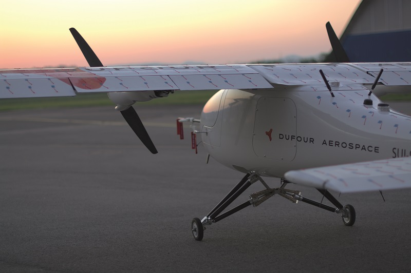
Dufour Aerospace Aero2
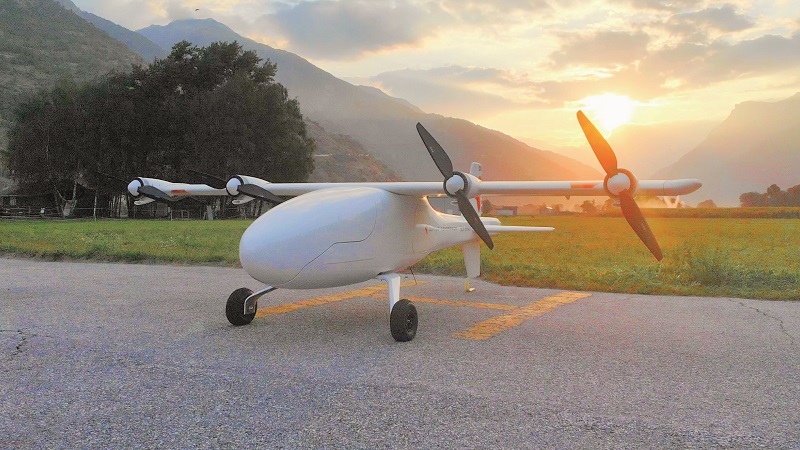
Rory Jackson explores how this large tilt-wing UAV is positioning itself as a long-range solution for commercial applications
A highly effective VTOL-transition system is key to building a modern multi-role UAV. An uncrewed aircraft that doesn’t need launch or recovery infrastructure, and can passively generate lift on fixed wings, is inherently a more flexible solution than one without these capabilities.
The demand for such solutions is reflected in our coverage in previous issues of different VTOL-transition configurations, including quadrotor-hybrids, tilt-rotors, tail-sitters and the unique transversely folding wing of the Pterodynamics X-P4 (issue 41, December 2021/January 2022).
However, tilt-wing aircraft – in which the main wing pitches upwards relative to the fuselage during lift-off to orient its propulsion nacelles vertically – are largely missing from the types that have had commercial success as UAVs.
Crewed tilt-wings are of course nothing new. For example, there was the 5 t Canadair CL-84, four of which were built between 1964 and 1972, and the 15 t Ling-Temco-Vought XC-142, of which five were built. However, mechanical failures and high pilot workloads resulted in them not being pursued at scale manufacturing.
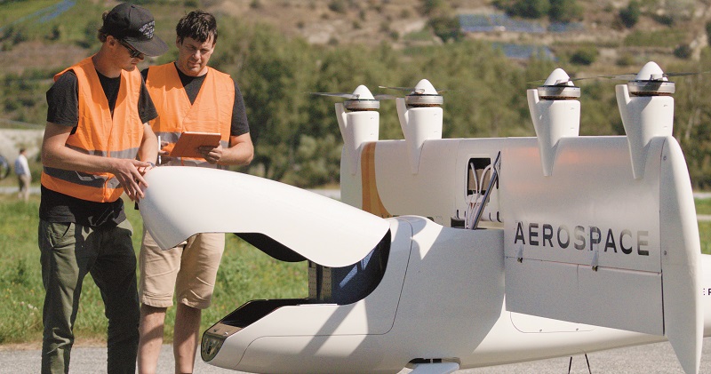
But just as tilt-rotor and tail-sitter configurations were also once shunned for crewed aviation, so Switzerland-based Dufour Aerospace is attracting attention for its Aero2 tilt-wing UAV. The company has designed its hybrid-powered, 208 kg MTOW UAV for a range of applications, particularly for users in cargo and medical logistics.
It has a 40 kg payload capability, a 150 kph cruise, a 3 hour endurance and a host of redundant systems. Most important though, the Aero2 incorporates technologies that overcome the issues with previous tilt-wings.
Company and design history
The Aero2 was conceived by Dufour’s co-founder and CEO Thomas Pfammatter, who was previously a helicopter pilot for emergency medical services. From 2015 to ’16, he had also worked with Dominique Steffen, another Dufour co-founder, to build the Aero1, the world’s first piloted electric aerobatic aircraft.
“They became enthusiastic about the power and efficiency capabilities of electric propulsion, and that drove them to start looking into possible eVTOL aircraft concepts,” recounts Jasmine Kent, the third Dufour co-founder and now its CTO.
“Around 2017, when they realised they’d need a much more robust control architecture than the manual system on the Aero1, they contacted me and presented their vision for a crewed aircraft that could replace helicopters in emergency medical transport. That focus looked much more impactful and interesting than most of the eVTOL concepts I’d seen – which were largely just air taxis – so I left my previous company and joined Dufour to develop flight control systems with Thomas and Dominique.”
That crewed eVTOL concept is now called the Aero3, and is planned to be a 2800 kg aircraft with a 13.6 m-long tilting wing, occupying a similar footprint to typical medical transport helicopters.
However, the three co-founders and their team decided first to develop a scaled-down prototype (as is conventional), the X2.0, to demonstrate the tilt-wing technology and prove its mechanics, aerodynamics and stability. “Potential customers were enthusiastic, and asked if we could sell them the demonstrator model,” Kent recalls.
Finding a huge market potential for a UAV of the X2.0’s size, a flight testing programme using the X2.0 was carried out in 2020, and in 2021 active product development of the Aero2 concept began.
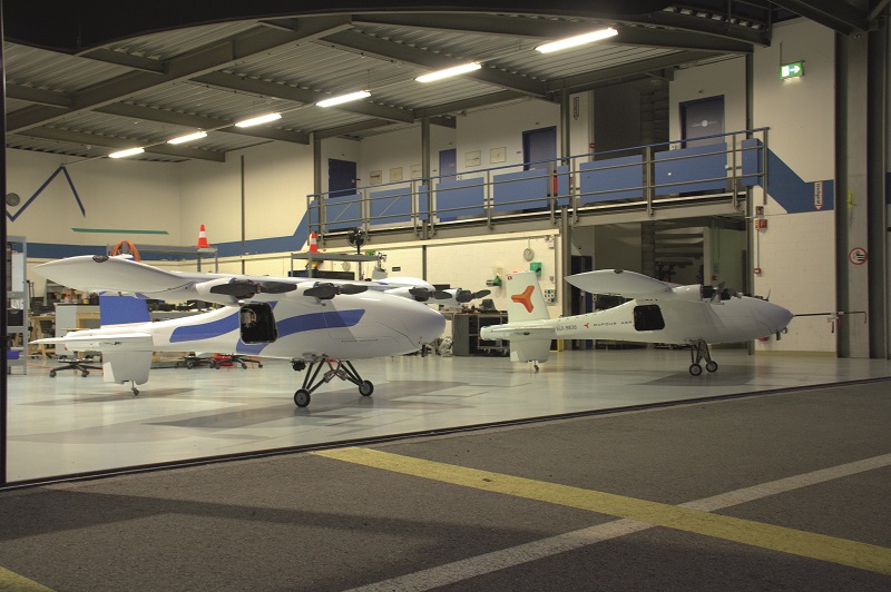
As part of this, the first iteration was the X2.1, which was far larger than the X2.0, and involved more rigorous design optimisation as well as bigger e-motors and batteries. The second was the X2.2, which is designed with series manufacturing in mind and which Dufour is currently flying for its r&d and test data.
“The next version will be the X2.3, which will be our pre-series production prototype with a range extender,” Kent adds. “That will lead directly to the series production aircraft, and we expect to start flying it early next year.”
System architecture
The Aero2’s layout is designed around the range extender, it being the largest and heaviest single component in the UAV. As it will make its debut in the X2.3, Kent points towards that iteration as the one for understanding Dufour’s engineering.
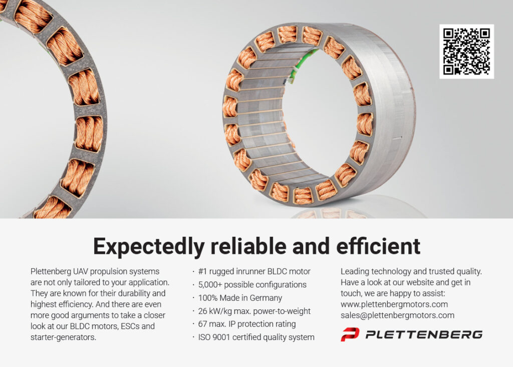
“The range extender consists of a Suter Industries engine and a Plettenberg motor/generator,” she says. “It’s positioned forward of the aircraft’s centre of mass [CoM], just ahead of the wing on the upper fuselage area, effectively providing a forward throw of mass to balance the UAV.
“Underneath is the payload bay, which is accessible via a hatch at the front of the aircraft. End-users slide their cargo under the CoG, which keeps the Aero2 from being too sensitive to weight changes. Our fuel tank is also accessible via that hatch, a little further back from the payload bay.”
To keep the batteries from affecting the CoM, the battery modules are distributed around the aircraft. That also reduces the required mass of cabling, with power going directly to the e-motors from local modules. It also prevents failures in one battery or motor from affecting the rest of the aircraft.
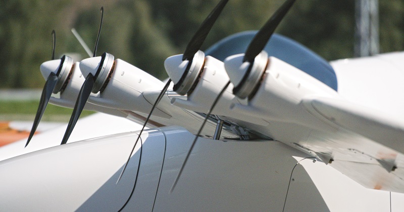
The Aero2 has a total of five electric propulsion motor-propeller pairs – four tractor motors on the wing, and one at its tail – with bespoke variable-pitch propellers designed for efficiency throughout all stages of the tilt-wing flight profile; the design is currently being evaluated on Dufour’s test bench. The tail motor augments lift from the main motors and provides pitch control during hover and low-speed transition.
Lastly, there is an avionics bay in the upper fuselage, just behind the wing. The avionics are accessible via a panel for maintenance.
Tilt-wing transitioning
Development of the tilt-wing mechanism took inspiration from past crewed tilt-wing aircraft such as those mentioned earlier – in fact the flight manual and history of the CL-84 played a key part.
“There’s a lot of other information available,” says Simon Bendrey, head of design at Dufour. “For instance, the US National Advisory Committee for Aeronautics developed aerodynamic profiles suitable for tilt-wings during the 1950s, with specific aero profiles for the wings and tail, specific locations for the hinge and how you throw the wing, and on the relative placement of the tail.
“There’s also a lot of data and feedback on the CL-84 and XC-142, which were highly rated at the time – they saw use by over 100 pilots in more than 1000 missions, and their aerodynamic performance, handling and control were all superb, despite their mechanical and workload drawbacks. So we’ve been able to use that to start with a basic draft for the Aero3, which was then scaled down to become the Aero2.”
On top of these, another key advantage of the tilt-wing configuration is that a wide range of airspeeds can be achieved at any given wing-tilt angle. The transition corridor is therefore not restricted to a narrow set of airspeeds and angular rates, as it is in some other VTOL-transition techniques.
As Kent notes however, “Those crewed tilt-wing aircraft were expensive, and the technology of the time meant their mechanical efficiency was poor. They needed multiple large turbine engines to provide the power needed for vertical flight, and for failure conditions each engine had to be capable of carrying the full 5 or 15 t of aircraft weight in VTOL.
“All this power was transmitted through driveshafts throughout the aircraft. And the control system was also mechanical, so they had rods and cables throughout. They also had a mechanical controls mixing computer, which was an incredible machine but very expensive to develop, build and maintain.”
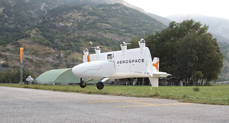
As well as using more efficient electric and electromechanical systems along with precise digital controls, much of the Aero 2’s anatomy has been shaped around balancing the craft sufficiently amid the slight movements to the CoM imparted by the 90o pitching of the wing during VTOL. During lift and hover, the CoM moves backwards, placing extra load on the tail rotor.
Some past tilt-wing models have been prone to cross-winds during take-off, hover and landing, owing to the wing’s large surface area. Dufour has therefore designed the Aero2 so that in windy conditions, when the propellers are inactive, the wing will be horizontal, so wind exposure on the ground is the same as a conventional fixed-wing aircraft. As soon as the propellers start working, ambient wind about the wings is absorbed by the much higher rush of air coming from the props.
“When we transition into cruise, the wing pitches downwards into its horizontal position, and that throws the weight forward, giving greater stability for cruise by moving the CoM ahead of the centre of lift [CoL],” Kent says.
Bendrey adds, “The CoL also moves backwards during transition, giving us a good static margin of stability and hence good balance for moving in and out of fixed-wing flight.”
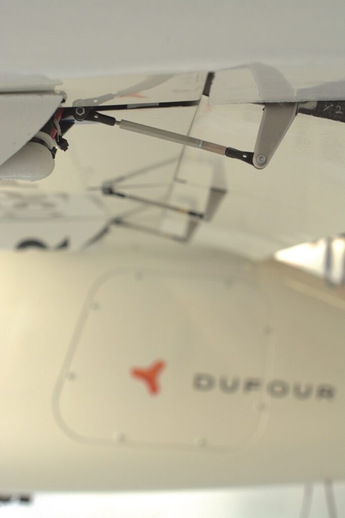
A linear actuator from TiMotion is integrated for controlling wing tilt, to cover the speeds needed and dynamic loads imparted during transition. It also holds the dynamic loading in a stable manner during cruise, as higher airspeeds – a key requirement for many UAVs working in industrial and emergency medical deliveries – will generate higher g-loadings.
“We can pull up to 4.5 g during fixed-wing flight, so the actuator needs to hold that much,” Bendrey comments. “There aren’t many parts available that have been optimised for a 200 kg UAV application, but the TiMotion actuator has an ideal degree of safety for our initial aircraft, which will be flying over sparsely populated areas.
“We’re also working with Maxon to find a redundant actuator, which we’ll need when we start flying over populated areas.”
The company adds that, while the aircraft would not survive a full prop failure in hover, it is extremely unlikely to happen – it has found the probability of that to be less than 0.0001%. In any case, hovering takes place only in closed or controlled ground spaces, so in the event of such a failure, no individuals would be harmed.
Propulsion and power
To provide the power and torque needed at the speeds the company wanted, a customised motor derived from a general aviation design was initially adopted. Since then, that design has been further modified to enable power and control redundancy.
“We’ve had bespoke motors developed by Geiger Engineering in Germany, and Plettenberg provides the tail motor,” Bendrey comments.
“Based on EASA’s Special Condition for Light UAS guidelines, and how rules and requirements have evolved since then, we’ve taken steps like developing and certifying our own flight computer to meet DO-178C,” he adds. “We also ensure at least 30 minutes of flight from onboard reserve energy, through our batteries and range extender, and touch-and-go missions are possible, in which we land and take off with full power coming from the batteries.
“An all-electric aircraft would land with reduced energy, because its batteries can’t replenish during flight. We don’t believe that’s been proven to be safe, so we recharge our batteries during flight to land with full power, do touch-and-go deliveries and still retain 30 minutes of reserve energy. And the FAA has recently announced that crewed eVTOLs are expected to have that level of performance too, maybe up to 45 minutes of reserve for night operations, which we could also offer.”

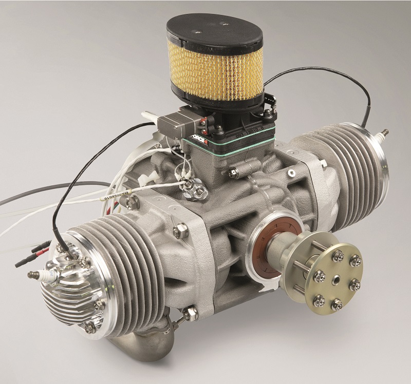
The choice of Suter Industries’ TOA-288 (a 288 cc, spark-ignited boxer twin weighing 8.9 kg and outputting 17.7 kW as peak power) as the core of the range extender came partly from it already being FAA-certified. Dufour also found it has the best power-to-weight ratio of any engine in the power range it wanted, and Suter’s location in Switzerland was helpful from communication, partnership and maintenance perspectives.
“I think they’ve sold close to 250 of those units now, all as primary power sources,” Bendrey says. “As mentioned, we’ve coupled it with the Plettenberg motor/generator.
“We needed something robust and industrial, and Plettenberg had some units that matched our requirements,” he adds. “We get 17.5 kW of shaft power from the engine, which is converted through the generator to 15 kW of continuous electric power. That more than meets our mission requirements.”
Ten 14S battery packs, each with 7200 mAh of energy capacity, are installed. Each pack has its own BMS to regulate in-flight charging and discharging, with a local charge controller responsible for determining how much energy is needed by each lift-thrust system, balancing for differences between how much thrust is needed at each rotor for stable manoeuvring, and how much energy is needed to keep each battery working safely and stocked with reserve energy.
“We run up to 58.8 V maximum, 52V nominal, and the generator produces between 30 and 58 V depending on total power required,” Bendrey says. “The highest current draw takes place in the short distances between the batteries and ESCs, which keeps our total cabling small and lightweight.”
Flight control
The layout of the Aero2’s control surfaces has been developed through analysing data from simulations and real-world test flights, and reflects Dufour’s desire for complete redundancy in power, control and aerodynamics. This is not a strict requirement for entering commercial service, but the company is determined that safety must be maximised if customers are to entrust vital cargo and other missions to an all-new aircraft.
Each of the Aero2’s two wings has two flaperons and two ailerons, while the H-tail structure has an elevator and two rudders, making for 11 control surfaces in all. That enables redundancy in the control of the UAV through all axes of freedom in hover, transition and cruise, so that safe flights and landings can be performed despite any system failures, be it an actuator, its power source or its control source.
“Again, there’s not much available in terms of servos for 200 kg UAVs – military actuators are too expensive, and hobby-grade actuators are too flimsy – but there are a few commercial suppliers that have the robustness and MTBF we’re after,” Bendrey says.
“We’re using Hitec for our independent control surfaces, specifically an industrial version of one of their actuators, while Volz provides our elevator actuator, which is fully redundant in power and control. The elevator works hard during transition to augment the pitch, so the Volz servo manages higher loads relative to the other surfaces.”
Dufour has over-specified the processor in its flight computer to leave bandwidth for future testing, optimisation and expansion of the flight control and autonomy stack (and achieve higher levels of certification in the future). At the time of writing, the prototypes were using single flight control systems without redundancies, but the design provides for redundant controllers depending on the use case and specific assurance integrity level.
“We use several different protocols in the aircraft, although we try to keep things simple and industry-standard,” Kent explains. “For the most part it’s CAN buses for the telemetry systems, serial links for electronics, PWM for actuation control, and separate power and control links going to everything so that none of the subsystems create interference with each other.”
The Aero2 uses a combination of inputs for navigation. Dual GNSS antennas are installed on top of the hull to ensure headings can be calculated during lift, descent and hover. The satnav also takes information from a MEMS IMU as well as a Simtec air data system designed originally for general aviation.
Fuel versus payload
The standard 40 kg payload capacity comes with an extra 12 kg of usable mass typically allocated to fuel for the estimated 3 hours of maximum endurance. Bendrey notes though that the weight allocated between the payload and the fuel can be redistributed as needed.
“The nose is modular, so the cargo door could be swapped out for a panel with an integrated gimbal,” he says. “If that gimbal didn’t need to retract into the hull, then an auxiliary fuel tank could fit where the cargo payload would normally go, for something like a 5-10 kg total sensor payload and 42-47 kg of fuel, which would take the total range to more than 1000 km.
“With 5 kg of payload and the remaining capacity being fuel, you could fly somewhere between 10 and 12 hours so long as you maintained the most efficient cruising speed of 130 kph.”
Dufour estimates that for each extra hour of flight time over the 3-hour, 40 kg suggested figures for cargo missions,
4 kg of payload must be reallocated to fuel. That comes out at 5.5 hours of flight time with a 30 kg payload, 8 hours with a 20 kg payload, or 10.5 hours with 10 kg – the last of these enabling 1390 km or 750 nautical miles of range.
For very urgent missions, the Aero2 can achieve an airspeed of 170 kph on generator power alone. Using all available power, a top speed of more than 250 kph is possible, albeit with the obvious trade-off in endurance.
While such missions might include high-speed deliveries of medical supplies or repair equipment, Dufour also promotes the Aero2 for search & rescue and public safety applications. For these, payload mass can also be integrated in the undercarriage between the landing skids, enabling a life raft or other similar items to be dropped wherever needed. Alternatively, that mounting point could integrate a synthetic aperture radar or other remote sensing devices that are too large to fit in the nose.
Structure and materials
Since the conceptual stages of the Aero3, Dufour has worked with carbon composites for their high durability-to-weight ratio, and has continued doing so with the Aero2. The X2.1 therefore has a fully carbon airframe, as do the X2.2 and X2.3, with each iteration optimising weight, robustness and stiffness.
“People think carbon is used just because it’s light, but while it is less dense than traditional aerospace metals, its fatigue performance is the real benefit,” Bendrey comments. “Boeing and Airbus are moving towards carbon airframes because they reduce the downtime that comes from inspecting for cracks and other flaws, so we too expect to have minimal downtime from structural repairs or overhauls over the Aero2’s lifetime.”
Dufour has used mostly standard carbon cloth, with some unidirectional (UD) fibre for bending strength and stiffness in the wing, as well as in the load-carrying portions of the fuselage. The carbon also contains a lot of aero-structural foam, and as this is a lightweight material that cures at low temperatures, the company manufactures much of its structural parts with an aerospace-standard, low-temperature cure, single-cycle lamination process.
The cloth, UD and resin systems come from Solvay, with parts manufacturing carried out by fellow Swiss companies Connova and Aerolite.
“As we’ve accumulated flight data and flown every part and permutation of the transition corridor, we’ve been able to confirm and validate our own load cases, rather than rely on past aircraft load data to define our structural needs,” Bendrey says.
“It’s been imperative that we investigate things like the aerodynamic interactions between wing, fuselage and tail, and remodel all of that in CFD software using Flow360. That gave us a suite of aerodynamic conditions and all the distinct kinds of landing conditions, which we then distilled into thousands of structural load cases.
“Then, using Hexagon’s Patran for FEM and Autodesk Nastran as our solver, we’ve sized the aircraft structures and done more localised analyses of hinges and joints based on interface loads. It’s all traditional stuff from professional aerospace, to directly support the Aero2’s certification.”
Dufour has also developed a patent-pending approach to the design and manufacturing of its aerodynamic surfaces, such is the challenge of reaching its eventual target of 1000 Aero2 units a year – which Bendrey notes is double anything currently made in general aviation – enabling a wing or control surface to be manufactured in 3 days with a single pair of tools.
“That’s around 30% of the time it normally takes,” he comments. “Over the last 20 years I’ve worked with the likes of Airbus, Bombardier and Pilatus, and historically it’s taken at least 2 weeks to assemble any wing, let alone manufacture the subcomponents.
“Our wing has integral ribs and spars, as well as brackets to support all the pylons, nacelles and anything else on the outside that connects near the actuator and hinge positions.”
While Dufour naturally declines to disclose specifics about its manufacturing methodology until the patent is granted, Bendrey hints that it is similar to how composite surfboards are made, with all the ribs, spars and internal brackets positioned inside the carbon surface wraps before they are compressed about their foam cores.
The fuselage is a monocoque design inspired by higher-end automotive body shells used in vehicles produced in runs of 500-1000 units per year, with a mixture of automotive and aerospace analysis to optimise the build quality.
Data links and operator systems
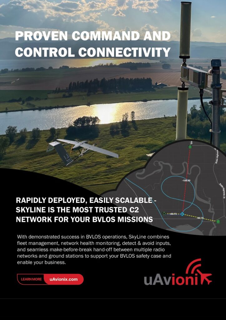
The Aero2 is equipped with 4G antennas and receivers to enable BVLOS flights over long distances. For practical purposes, Dufour’s long-range use cases rule out LOS links, and make cellular comms a hard requirement.
“We also have a unit that enables us to use 5G and satcom as well, with the key priority being that the C2 link is always live,” Bendrey says.
Regarding GCSs, Kent says, “We have developed our own stack in-house, but our general approach is to offer a smooth integration path for customers’ existing operational frameworks. Typically, our customers are already doing some kinds of BVLOS missions, and they’re going to be adding our aircraft to their operating models. Straightforward interfacing is the best thing for that.”
Future plans
The company’s launch customer is Spright, the UAS division of Air Methods, a US provider of helicopter emergency medical services. Spright has bought 40 Aero2s so far, with an option for 100 more, and is due to deploy them in sections of its hub-and-spoke delivery operations.
Other customers have not been publicly announced yet but it is known that they are focused primarily on logistics, particularly medical supplies or industrial spare parts. Many are also interested in ISR, mapping and scanning applications; Dufour estimates a 60/40 split between cargo and survey interests.
The company is also planning to start demonstration flights soon outside Switzerland to show that the Aero2, along with its supply chains and manufacturing, are all at a high enough TRL to be entrusted with critical mission requirements within the next few years.
Specifications
- Aero2
- Tilt-wing VTOL transition
- Hybrid-electric (IC engine range extender with electric motors)
- Wingspan: 6.1 m (20 ft)
- Length: 4.1 m (13.4 ft)
- Height: 1.87 m (73.6 in) with wing tilted upwards
- Payload weight capacity (excluding fuel): 40 kg (88 lb)
- MTOW: 208 kg (459 lb)
- Maximum endurance: 3 hours
- Range: 400 km (216 nautical miles)
- Optimum cruise speed: 150 kph (81 knots)
Some key suppliers
- Engine: Suter Industries
- Generator: Plettenberg
- Electric lift and forward propulsion motors: Geiger Engineering
- Tail motor: Plettenberg
- Airframe composite materials: Connova
- Structural composite materials: Aerolite
- Resin systems: Solvay
- Air data systems: Simtec
- GNSS: u-blox
- Servos: TiMotion
- Servos: Maxon
- Servos: Hitec
- Servos: Volz
- Design, development and testing support: RUAG
- FEM software: Hexagon
- FEM software: Autodesk
- CAD software: Onshape
UPCOMING EVENTS


