


Electric motors
(Image: Scorpion Power System)
Get your motor running
Matching the electric motor to the uncrewed vehicle requires patience, a sharp ear and skilled engineering; optimising that motor takes a little extra. Rory Jackson investigates
In the uncrewed space today, electric motors are essential to a growing majority of vehicles’ propulsion, whether as VTOL rotors, starter-generators or otherwise. However, movements and happenings in electric motor r&d are marked not so much by waves of new technical advancements, but by the pace at which suppliers can configure and optimise batches for customer needs.
Part of this comes down to how existing electric motor architectures are running against limitations imposed by the very laws of physics, which cannot simply be brute-forced past with a new form of winding or permanent magnet.
Moreover, no particular single motor is suitable (let alone optimal) across all use-cases: one may find e-motors that reach their optimal power efficiency at high speeds and low torques (such as 15,000–22,000 rpm and 2–3 Nm) for helicopters requiring high-speed gearbox drives, ones that run best at low speeds and high torques for multi-rotor applications (2000–3000 rpm and 8–10 Nm), and ones that strike a middle balance for fixed-wing UAVs (7000–10,000 rpm and 4–5 Nm).
Also critical to consider are how speed, torque and efficiency interplay with SWaP-C. More thrust can always be achieved by making a motor bigger, heavier and more power-hungry; similarly, optimising for efficiency takes labour-hours and r&d expense. However, not only can these parameters easily spiral beyond a customer’s limits if not specified closely enough, or not adhered to by a lower-end supplier, but they do not account for the reliability of motors across their lifespans: a vital consideration as commercial UAVs inch closer to legally flying over populated areas.
Additionally, as defence organisations rapidly grow their adoption of uncrewed systems, optimising e-motors for low-cost and high-speed manufacturing, for getting UAVs, USVs and more to the front lines as quickly as possible, becomes equally as critical as continued production of efficiently performing, high-reliability motors for civilian applications.
Hence, custom optimisations aimed at suiting the motor to the application and the mission-specific safety requirements, are, in many ways, more important for electric motors than for most other uncrewed vehicle components.
Occasionally, the optimal e-motor is identifiable at a distance: a high-speed, low-torque motor, for instance, will generally have a narrower, lengthier shape than the much flatter, wider low-speed, high-torque devices. Other factors such as pole counts, copper packing densities and magnet selections are known levers with which more experienced motor manufacturers will be able to tailor and optimise for hitting (or occasionally exceeding) customer specification requests.
(Image: Fischer Panda)
But beyond these, there remains considerable scope within electric motor technology for unknown factors to yield improvements in SWaP, performance and reliability. A small handful of companies within the e-motor industry pride themselves on undertaking novel, unconventional r&d, from peculiar vehicle projects to experimental tests and design experimentations – a vital philosophy and practice for meeting the needs of the still-growing, maturing and experimental uncrewed world.
Design
With that in mind, we find two schools of thought when it comes to how suppliers develop new electric motor configurations to suit customer requests or contracts. One is that based on experience and known scientific conventions of electromotive physics, as accumulated and closely understood by electric motor suppliers – particularly among those engineers and companies that evolved away from model aircraft motors prone to burning-out within 15–20 seconds of full throttle operations into UAV motors of certifiable quality.

This encompasses a range of practices and options, such as choosing the right stator wire with ideal coatings and winding architectures for the power output and environmental use-case, along with high-quality silicon steel for ensuring good conductivity and magnetic flux from the stator, or selecting suitable permanent magnets made from certain grades of samarium cobalt or high-temperature neodymium to fit a particularly high-power, high-heat application. Optimising stator designs, rotor designs, bearing choices, housing designs and mounting options – and proving them through testing and iterative improvements – are also crucial disciplines that are well understood by experienced motor manufacturers.
Such a close understanding of these levers is critical because, 95% of the time, changing an existing motor design’s windings to adjust its Kv-rating – that is, its full throttle speed in rpm at a given input voltage, unloaded – is sufficient to achieve most customer-requested performance and efficiency specifications, with the rest forming the final 5% of optimisations, along with case-specific variables such as a particular shaft, connector, mounting format and the like.
Blank sheet designs, however, typically only arise in response to very novel or unusual requests, such as those UAVs, USVs or AUVs pushing beyond typical vehicle sizes, payload carry capacities or high-speed manoeuvring. Experimentality is increasingly a critical factor within the organisational culture of electric motor manufacturers because it periodically takes (for example) unconventional stator designs or shaft designs to hit a certain torque-to-weight ratio or peak power output deemed impossible – and hence, dismissed or refused – by well-established engineering houses and major aerospace OEMs.
It is also entirely natural to increasingly rely on CAD programs to simulate magnetic flux, thermal behaviours, points of optimal efficiency and so on. But uncrewed vehicle manufacturers frequently request motor designs that hit new heights of combined speed, torque, power, electricity, heat, weight, magnetism and aerodynamics – for which there is, obviously, little prior data to draw upon.
Thus, CAD programs, being based entirely on empirical data, cannot predict with good accuracy how entirely new designs or materials for motor subcomponents will affect performance at the system level; it is not unheard of for trials of a new stator design – one going against the grain of logical, established engineering – to result in power improvements, rather than degradations, when run in a test stand. And so, possession of great drive to try new part geometries, materials, arrangements and so on, along with extensive testing regimens and equipment, sets apart good motor suppliers from great ones.
Testing
Essential to any motor manufacturer are test stands capable of measuring rpm, temperature, current and voltage. These four stats can be mapped against one another on graphs to interpolate motor efficiencies against speed, torque and power. Such graphs are also critical tools for comparing one motor against another, such as current and former generations of a new prototype under development, or a new in-house formulation against a competitor’s unit.
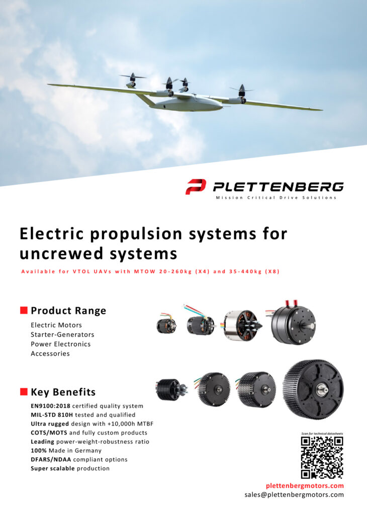
(Image: Plettenberg)
However, understanding why one motor is better than another, or identifying exactly where along the power curve one surpasses another, is more challenging. Carrying out exhaustive test permutations is one way to achieve this understanding.
Another is moving to more advanced, modern motor-propeller test stands, specifically capable of measuring thrust, torque and other factors directly, across full curves of speed, power and so on, on top of the four standard parameters mentioned above. It is also valuable to have highly digitalised stands that can gather all of these data with more points per second, and export all of them in map form upon request, saving test engineers much of the work of putting together their own charts manually.
By gathering higher-resolution test data on wider sets of parameters, engineers can map down the precise locations and extents across performance maps that one motor outperforms another, and hence start to understand where, in a physical or software sense, one motor’s advantage might be coming from and thus where further gains might be had.
And as important as such testing equipment is to helping extract the final 5–10% of performance out of a customer’s motor specifications, even further gains can be made at the vehicle level by devoting test stands and benches to trialling the other components of an electric uncrewed system’s powertrain.
These can include testing new hardware such as electronic speed controllers (ESCs) or propellers, and thus identifying new means of gaining overall powertrain performance or efficiency using new architectures, sub-components or topologies for these. New field-oriented control (FOC) algorithms for motor commutation may also be coded, with digitalised, precision-measurement equipment enabling rapid trialling of newly written or sourced variations of individual modules or subroutines to build the best overall control algorithm for the application.
In addition to executing more valuable tests, motor manufacturers are also trying means of performing tests more quickly. One route has been to additively print rotors and stators to rapidly prototype and either validate or improve new electrical, thermal or high-level mechanical configurations.
And beyond running broader or more efficient test envelopes on their own volition, high-end motor manufacturers keep an increasingly close eye on new standards to which their products can be proven or upgraded. Mil-Std 810H standards on environmental ruggedness, for instance, were released in 2019 (with the most recent Change Notice 1 coming in 2022), and a small number of e-motors have been certified to 810H by undergoing months of temperature extremes and shocks, as well as exposure to sand, dust and salt fog. And as voltages and current throughputs rise, certifications to higher and higher standards on EMI and ESD will become safety-critical for uncrewed vehicle operations and technicians.
Hence, even if electric motors prove a challenging technology to advance further, manufacturers of such systems can clearly benefit from relentless testing and iteration of their designs because such activities indisputably lead to better gains and optimisations for each individual customer, even without needing to use groundbreaking new winding topologies, magnetic materials or other areas where technological breakthroughs might have been overpromised in the past.
Manufacturing
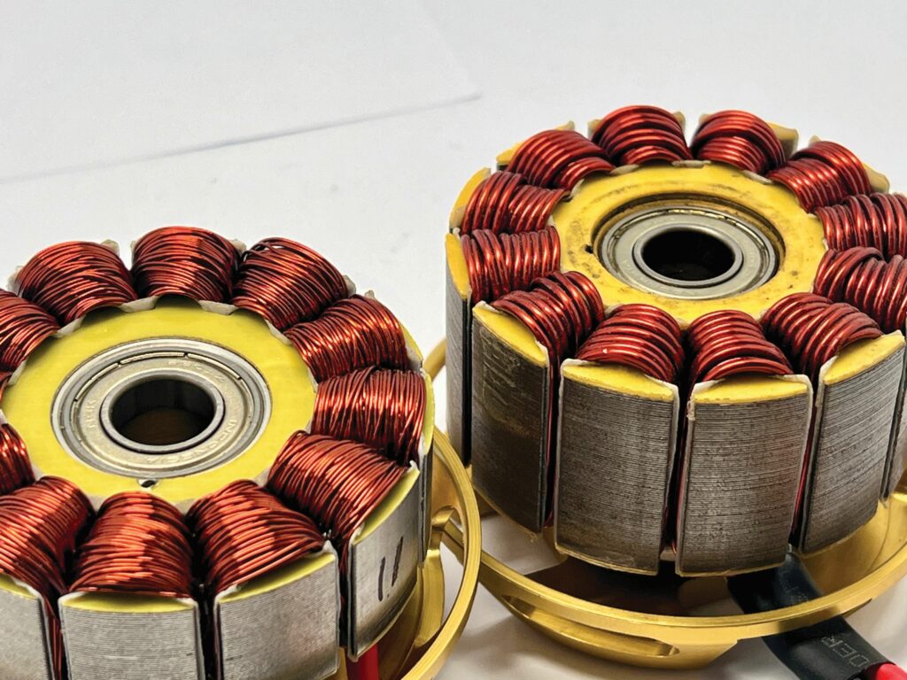
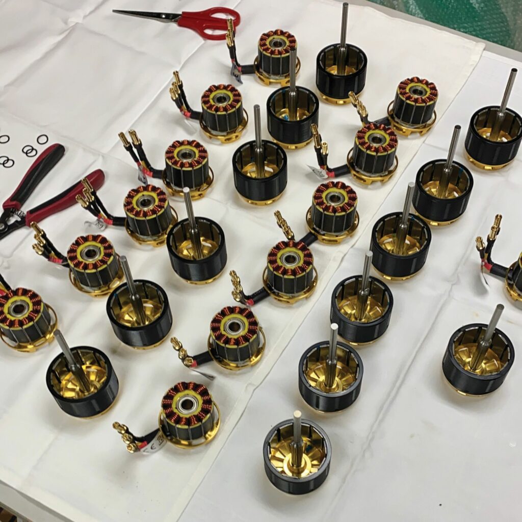
The majority of electric motors used across the uncrewed world are, by convention, manufactured in a somewhat artisanal way, particularly with respect to stator production. Hand-winding of insulated wires remains the best way of maximising the packing density of copper windings about stator teeth, given the intangible way humans are able to visually scan a stator and translate that into correct twisting, pressing and squeezing by their fingers – unlike machines, both as of writing and likely for many decades to come (at least, not any commercially affordable or scalable machines).
This poses an issue for modern military chiefs who dream of churning out swarms composed of thousands of multi-rotors per month because most high-end electric motor suppliers opt out of having the capacity to produce such numbers at such speed: hand-winding remains the primary bottleneck to completing e-motors quicker, but skipping or skimping this step inevitably reduces motor performance and quality – not something any motor manufacturer wants to be known for – and it can only be sped up so much.
Upping e-motor throughput can only be achieved in two ways. One is simply hiring more stator-winding technicians until workshops are filled with rows of winding workers at desks, toiling away with mute focus through bundles of dark red wire.
The other way is automation, which some high-end manufacturers are undertaking specifically for defence customers’ attritable (or even single-use) uncrewed systems in need of bulk orders of e-motors that perform reliably but do not need to live especially long.
Automation is not a simple matter of ordering-in winding machines because the machine must be closely engineered and configured to a particular order of motor sizes and shapes, and each machine takes considerable time and money to develop and optimise.
Instead, automation begins with the manufacturer designing their motor for automated manufacturing: this invariably means an outrunner design, with the stator teeth facing outwards and the gaps between each being easily accessible to a gantry-controlled (or similar) winding machine.
Correctly designing the stator for automated winding can reduce this step’s duration from 60 minutes by a skilled engineer to 3 minutes by a machine – although, naturally, several challenges must be overcome, such as preventing too tight a design that risks damage to either the stator or the copper wire by the machine’s actions, or one that results in a very poor copper packing density.

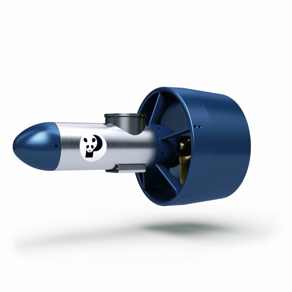
(Image: Plettenberg)
Various other production steps can be accelerated, starting with identification of these steps through mapping and judiciously scrutinising each motor’s full value chain for any stage lasting more than 10 minutes. Designing the rotor for easier magnet installation, or interfacing with the stator and bearing, for instance, are additional pathways towards handing-off duties to gantry and robotic arm machinery, with existing UAV motor manufacturers having achieved this with outrunner rotors already, their machinery pushing the magnet pieces outwards into the rotor and completing the magnet bonding process within minutes.
Additionally, the base metal of the rotors, stators and housings is typically CNC-machined, a process that can be fully automated through use of robotic arms for removing and inserting metal parts from one machine to the next (and into automated QC measuring equipment between or after machine tooling stages).
However, means of automating certain steps still elude engineers, and too much automation (with no room for manual adjustments) would take away the ability to customise for application-specific performance or material requirements; hence, some processes such as rotor balancing and stator potting will remain semiautomated and reconfigurable on the fly.
Quality control
Although automated manufacturing comes with significant expenses, not to mention optimisation losses compared with more manually produced e-motors, one key advantage is how QC systems can be seamlessly integrated into the production process, with cameras, laser scanners and similar devices often being integrated at key intervals along the manufacturing chain. Hence, much quality is controlled before completed units ever roll off the end of the production line.
Thorough end-of-line testing is particularly important for hand-wound motors, given the natural potential for human error, and high-end suppliers run batteries of non-invasive tests to guarantee correct performance and keep output unit failure rates low (often below 0.05%). Initially, such tests will include obvious practices, such as running each product on a bench to validate that the Kv-rating is correct and that there is no peculiar voltage, current, noise or odd behaviour such as inexplicable flashings of light or heat coming from inside the motor.
The wider range of tests can include checks of the stator wire’s internal resistance and inductance to prove whether it has been wound correctly because winding the wrong number of turns, for instance, is a surefire way for these parameters to detract from their expected values. Identifying whether the enamel coating has been nicked across any portion of wire is another pass–fail criterion, which can be performed through a voltage isolation test to reveal signs via short-circuiting.
Checking the rotor via simple running and balancing tests is also necessary to discern if the permanent magnets have been glued correctly (and that the rest of the rotor manufacturing was performed to specification). But as more and more electric motors come supplied as complete propulsion pod systems, pre-integrated with propellers, ESCs, cabling and rotor arms, the ability to validate quality and consistency in those related components grows in importance.
Electronics such as ESCs are markedly more challenging to quality-control for faults and failures that may pose a risk to an uncrewed vehicle’s operations, not necessarily because of any inconsistencies on the part of ESC producers, but because running small powertrains of 5–10 kW or higher to their limits will inevitably induce new heights of mechanical, thermal and electrical stress, often beyond those envisioned and tested for by such suppliers.
(Image: Scorpion Power System)
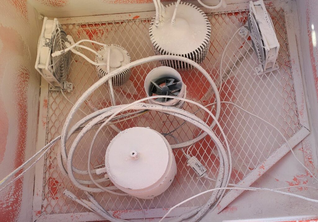
Hence, on top of standard automated visual inspections, 100% functional testing and loaded testing are vital to identifying, for instance, whether the silicon MOSFET itself has a defect, including full power cycling of each ESC in an oven, to expose in the workshop whether an issue may occur in flight or at sea. This is also highly recommendable for fully integrated propulsion pods, even if it means running randomly or periodically sampled pods off the production line on a series of test stands, inside a temperature chamber, for functional lifetime testing to ascertain desirable performance, assembly and component standards.
The big freeze
While one may walk away from an overview of electric motor tech feeling that they have reached the absolute limit of their advancements for the uncrewed space, some notable challenges lie in the future of small electric powertrains that will bear clever thinking to deal with effectively.
For instance, the advent of semi-solid-state batteries stands to greatly improve battery safety, but these new devices come with around 2.5–4.2 V DC per cell, expanding noticeably upon the standard 3.7–4.2 V nominal range per cell of a traditional Li-po system. Accordingly, a 12S pack, usually specified at 44–50 V DC, will supply power at 30–50 V DC when integrating semi-solid cells.
This matters because such a widened voltage range is much harder for electric motors to handle: when such a pack is fully charged, a motor will spin at the top of its speed range, given that each motor’s Kv-rating is given as rpm/V. As that pack approaches a 0% SoC, its voltage will draw down to 30 V, meaning it will near a 40% difference in voltage and hence a comparable difference in the motor’s rpm, impacting in turn its power and current output. That risks the uncrewed vehicle’s motors slowing, losing power, potentially overheating or suffering other issues that mean a failure at the system level, possibly resulting in a crashed UAV, a sunken AUV and the like.
Mitigating this issue by wiring the motor’s stator for better efficiency at low voltages is a poor trade-off because it will almost inevitably lose efficiency at its higher voltages, including the possibility that overpowering and overheating occur at higher voltages.
A likelier solution is if electric motor and powertrain developers can develop better commutation algorithms over time, allowing ESCs to more closely regulate input voltages to match motors’ sweet spots. This can be balanced with strategies such as winding a motor for efficiency towards the lower end of its battery pack’s voltage range, and then algorithmically limiting the voltage such that the motor never gets hit with the higher voltage power inputs or the associated overheating risk. That would mean improved safety for the motor, and for overall flight control in UAVs, by keeping the ratio of the throttle signal to thrust from changing excessively with battery voltage.
As much as preventing overheating through better control algorithms relates to adapting for new battery tech, thermal management in general is likely to become an important pathway for improving electric propulsion into the future. If two identical motors are run, one at 50 C and the other at 70 C, the latter will naturally accumulate wear in its shaft, bearings and other parts at a much faster rate; conversely, designing a motor to run cooler helps all internals – and MTBFs – last longer.
Much is being progressed to this end through mechanical approaches. For example, different forms of integrated fans for using the rotor to sweep coolant air through the stator windings are being optimised, including both external, axial, internal and radial designs, with pushes for improvements in fan configurations frequently achieving 10% reductions in motors’ internal operating temperatures. As well as extending motors’ lifespans, that naturally also means less current is lost via heated-up copper windings, and there is also less heat to get transmitted downstream to the ESC, making for higher power efficiencies across the powertrain.
Mechanical approaches to thermal management often run into trade-offs, however. Using a rotor to pull air through the motor interior risks inducing drag on the rotor and hence parasitic losses into the motor, and optimising cooling fin designs around a motor housing may introduce extra production complexity and cost owing to unusual fin geometry.
Rather than trying to get better flow around the outside of the stator or motor, an alternate tactic is to design stators with wider, hollowed-out cores such that air or liquid can flow through the inside, extracting heat almost directly from the windings. However, expanding the stator core will probably mean reducing the copper packing space for a given stator diameter because the stator teeth must be shortened by however much the core was widened, and so the resulting max power drop may exceed the operating power improvement gained by improving the cooling system.
Researchers vary in their enthusiasm as to the potential of better thermal transfer materials in UAV-sized electric motors, from known, simple thermal pastes and better stator potting compounds all the way to advanced phase-change materials. But from an efficiency point of view, a general trend towards higher voltages – towards 120 V and likely exceeding 150–200 V in some heavy lift and autonomous air mobility applications – is increasingly expected.
Given two motors built identically, save for one being wound for 50 V and the other for 100 V, the latter will produce around 10–15% more thrust at the same power consumption. Follow-on benefits such as lighter cabling and connectors to suit the reduced current throughputs will also serve as motivators for UAV manufacturers to demand higher-voltage electric motors, as has been the case in EVs for some time.
It will be a great while before UAVs start using e-motors with a size and parts list comparable to those used in aerial or road e-mobility, where architectures of 800 V are becoming the norm. Until then, the uncrewed world is more than adequately equipped with suppliers of high-end systems who practice well the means for optimising their electric motors, and more importantly, listen closely to their customer’s word.
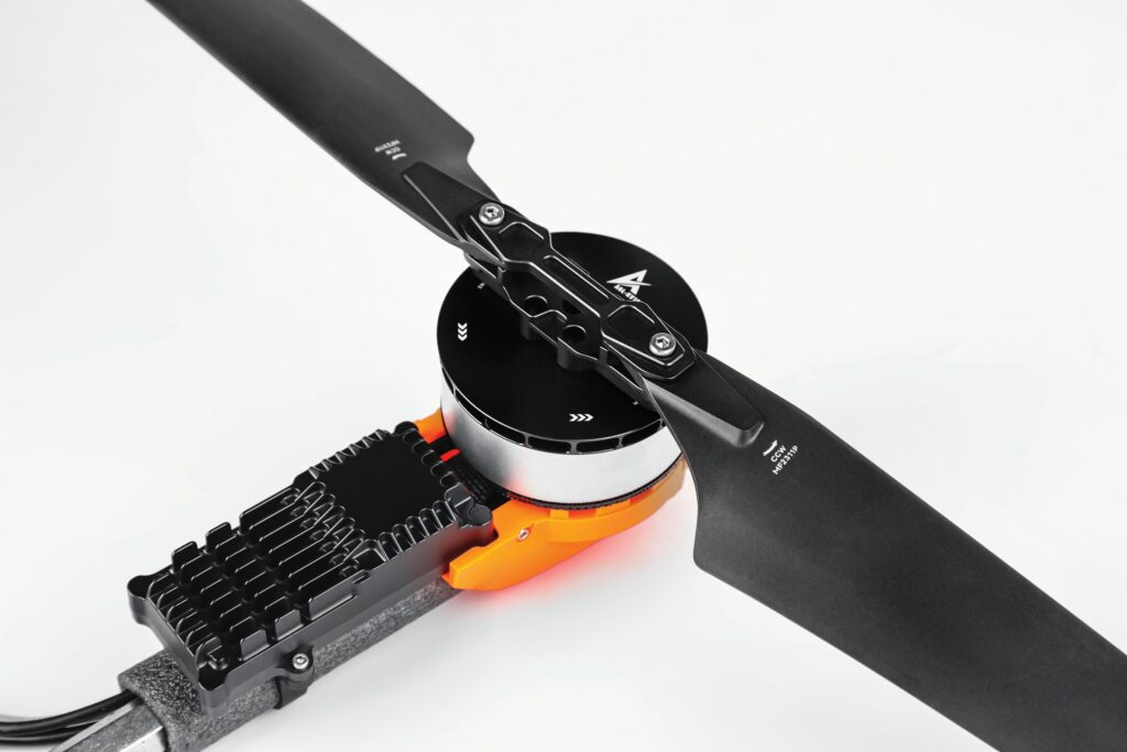
(Image: T-Motor)
Acknowledgements
The author would like to thank Bastien Greiner of Plettenberg, Kyle Dahl of Scorpion Power System and Chris Fower of Fischer Panda for their help in researching this article.
UPCOMING EVENTS


