


IMUS, gyros and accelometers
Driven by military concerns, the latest IMU and INS systems are pushing beyond today’s frontiers, as Rory Jackson finds out
The uncrewed systems world is vast, complex and multifaceted, which can make it difficult to identify the trends that are genuinely affecting the majority of vehicle and subsystem manufacturers.
That said, in navigation systems there is a definite move away from absolute dependence on the global navigation satellite system (GNSS) for localisation and guidance towards the fusion of inertial data, with varying combinations of visual, radar, laser, acoustic and other sensor feeds.
This is being driven by a combination of military concerns over GNSS jamming or spoofing attacks and general concerns over multipathing and frequency-band congestion as the global population of uncrewed, Internet of Things (IoT) and other GNSS-transmitting/receiving systems increases.
Inertial systems, by contrast, cannot be congested or frustrated in the way satellite signals can. Moreover, lacking the numerous weaknesses of the other sensor types, they remain a critical hallmark of modern navigation.
On top of this, the performance requirements placed on inertial systems by uncrewed systems customers (and hence manufacturers) are increasing as appetite grows for accurate data and smarter vehicles. This doubly goes for anything carrying a payload gimbal: whether it’s flying a UAV for search-and-rescue efforts, counterterrorism agents or a multi-million-dollar movie or sporting event, coupling an extremely high-end inertial device with the UAV’s gimbal is the only guarantor that its camera will be able to track its target with precision.
As a result, inertial measurement unit (IMU) and inertial navigation system (INS) manufacturers have spent the past few years innovating their products to offer myriad improvements down the complex list of performance and physical specifications that gauge their capabilities and worth.
As well as integrating new and improved components into their solutions, companies are enhancing their manufacturing facilities to optimise production output and costs, and devising new means of leveraging external aiding sources to go beyond the traditional INS for tomorrow’s uncrewed vehicle.
Size, weight, power
Some readers will doubtless be familiar with the ecosystem of IMU types. For those who are not, there are three broad categories, across which size, weight and power (SWaP), and performance quality are all positively correlated. Performance encompasses varying facets of accuracy, precision, measurement range and resolution, and resilience against drift, as well as other forms of error.
At the lower end of the three categories are microelectromechanical system (MEMS) IMUs. Fibre-optic gyro (FOG) IMUs are typically associated with higher performance and SWaP-C (cost), with ring laser gyro (RLG) IMUs the highest across all categories. MEMS are generally the most prolific among uncrewed systems, followed by FOGs.
RLGs are the rarest, traditionally only seen in very long-range, long endurance UUVs and some spacecraft, and they are seldom built or marketed explicitly for uncrewed systems engineers.
An oft-repeated catchphrase describing the future of US defence strategy is “small, cheap, smart and many”, which one might apply not only to the uncrewed swarms that defence futurists around the world envision, but also to MEMS devices, which continue to strike the lowest SWaP-C figures and the highest production outputs via their sensing instruments.
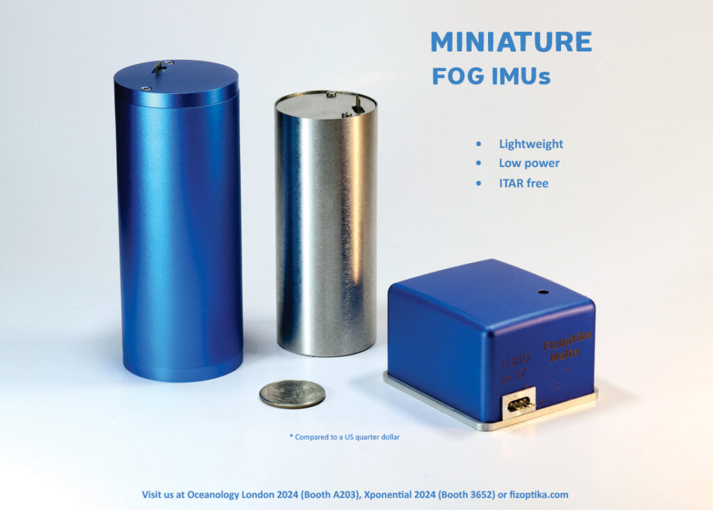
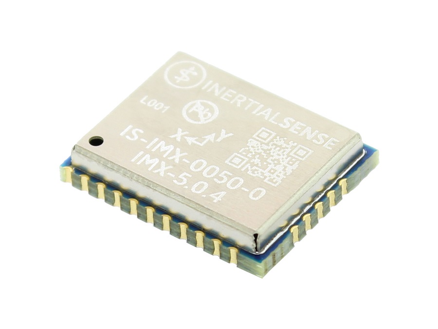
Among the latest MEMS IMUs available for uncrewed systems are devices weighing no more than a few grams, with some rare high-end products lighter than 1 g, only a few millimetres tall, and 15-20 mm wide and long.
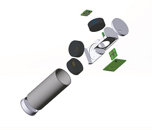
(Image courtesy of Fizoptika)
Making an IMU smaller and less expensive typically means reducing its sensitivity, and hence its sensing performance, but such devices are integrating gyroscopes capable of in-run bias stabilities of less than 1.5°/hr and random walk values of 0.16°/√hr, along with accelerometers whose in-run bias stabilities are below 19 μg with random walks of 0.2 m/s/√hr.
Such systems can be integrated as subsystems into more complete solutions, such as the attitude and heading reference system (AHRS) or the INS with dynamic roll and pitch accurate to 0.04°, or dynamic heading output to 0.13°.
Reaching these figures uses some proprietary IP, guarded by IMU companies, but much of it comes from carefully picking among MEMS suppliers to find the latest technology. Accelerometer and gyroscope fabricators typically take three to five years between step improvements in the SWaP, performance and production throughput of the vital core components they supply to IMU makers.
Those components are predominantly silicon-based, although MEMS made from metals, silica (silicon dioxide, also known as quartz), ceramics and plastics are also commercially available. Regardless of material, the core principles remain the same: a microscopic structure is designed to move in response to acceleration (an accelerometer) or angular rate (a gyroscope), with that movement inducing a corresponding voltage that can be detected, measured and reprocessed into inertial – and hence movement – information.
Ever smaller
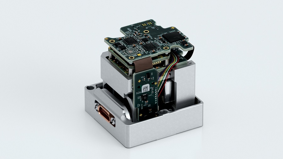
On top of this, manufacturers are leveraging high-density printed circuit board (PCB) designs to pack MEMS into smaller product enclosures, without leading to interferences or resonances inside those spaces that could degrade performance. Additionally, optimising these designs is still hugely dependent on real-world prototyping, testing and iteration; such are the myriad nuances of IMU performance that virtual simulations cannot yet capture.
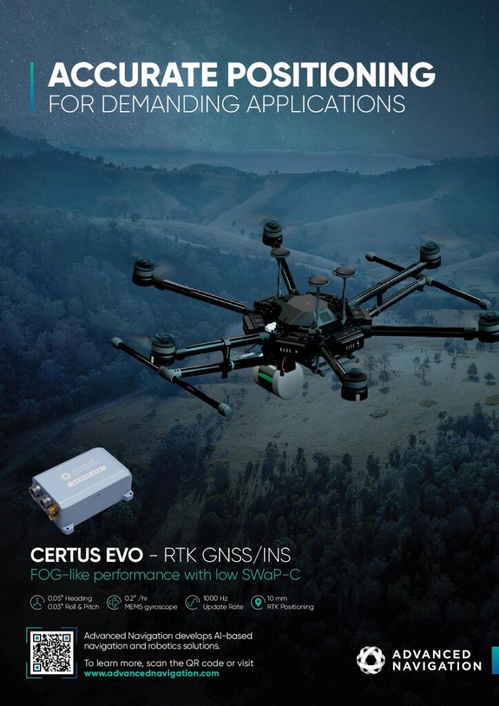
Although MEMS may be a byword for minimised-SWaP, fibre-optic inertial systems have also made huge strides over the past few years to create FOG-based IMUs that can be as light as 100-200 g. While this remains many times heavier than the lightest MEMS IMUs, it is multiple times lighter than the typical commercial FOG IMU offerings for uncrewed systems just a few years ago.
This new wave of systems gets by on 1-2 W of power in standard operations, output readings with angular, random walk values of 0.03-0.05°/√hr and bias stabilities of about 1°/hr. Such devices perform with high immunity to magnetic interference by leveraging either internal or external magnetic shielding, with magnetic response values of 0.1-0.3°/h/Gauss.
The ability of FOG IMU manufacturers to push SWaP limits without scuppering performance comes from a similar place to many other advancements being made in FOG-based systems (which we will expand upon), and that involves leveraging advances and experience in fibre optics from across industry to create ever-smaller sub-components.
The principal bottleneck is the physical bend radius of the fibre itself – bend it tighter and you create a smaller circle, and hence a single-axis FOG with a smaller footprint, but bend it too tightly and you risk breaking the fibre.
Among the smallest FOG IMUs we have seen in the uncrewed space, the fibre of choice is a polarisation-maintaining fibre (PMF) with a thickness of 40 µm. Linearly polarised light maintains its linear polarisation state during propagation and when exiting the fibre. The choice of PMF is key to highly precise interferometry; the process by which FOGs sense angular rate, while the thickness enables the fibre to be wound in circles tight enough to manufacture FOG IMUs with radii of 20-25 mm.
As we will discuss, other FOG (and MEMS) companies are making similarly judicious choices for the growing variety of IMU architectures appearing across the market, with optimisations going beyond just SWaP.
All in the timing
For customers seeking IMUs for navigation applications, precise timing is a critically valued quality, often as important as in-run bias stability, as without proper time synchronisation it is impossible to correctly consolidate inertial data between different accelerometers and gyroscopes in an IMU, or between an IMU and its external aiding systems, such as GNSS receivers, Lidars or cameras.
Scale-factor errors result from poor time synchronisation in inertial systems, which can then accumulate over time into severe navigation drift, owing to the discrepancy between an IMU’s clock and the uncrewed vehicle’s clock. The severity of that will increase with the dynamics of the vehicle, making higher-speed UAVs and UGVs particularly vulnerable to timing-related errors.
Time synchronisation is a complex robotics problem, which companies often resolve through a robust events-management system to ensure timestamp accuracy within and without an IMU. Key elements of such a system include a number of different inputs for synchronisation purposes; for instance, the software can be defined such that every pulse of inertial data output triggers an event with a specific log timestamped using the IMU’s internal clock.
Alternatively, an event-marker log can be sent whenever an event external to the IMU (such as a Lidar pulse, a camera shutter or a GNSS update) is received, be it by CAN, GPIO or other network bus, thereby timestamping each event. And, often, when integrating an IMU with a GNSS, a key part of the overall INS design is utilising the GNSS’s pulse-per-second (PPS) signal to realign and synchronise the IMU’s clock to the GNSS clock (the latter being typically defined by an atomic clock, placing them among the most trustworthy sources of timing data).
Low latency
Another critical part of ensuring accurate real-time control is minimising the output latency of inertial systems; that is, the time delay between when a motion is imparted on the IMU and when a packet of data capturing that motion has been generated and output. Keeping latency as low as possible is vital to ensuring precise control loops, both in navigation and gimbal pointing. This can largely be accomplished through software, specifically via an extended Kalman filter, optimised to calculate and output data packets using only minimised and condensed computations of the raw motion data.

Also worth noting within the umbrella of timing- and latency-related performance parameters is timestamp repeatability. This refers to variances in timestamp accuracy, which are typically introduced via internal hardware-processing delays, and are hence resolved through the selection of higher-end components, as well as the testing and iteration of board designs to minimise concentrations of crosstalk or hotspots.
Furthermore, mitigating problems stemming from hotspots, and generally ensuring the consistent performance of an IMU across temperatures, remains a vital guarantor for success in real-world applications, and failing to do so results in comparable degrees of output error to timing failure.
Uncrewed vehicles increasingly undergo wide ranges of environmental temperatures during their missions. Robots running deliveries or industrial inspections, for instance, will drive (or walk) inside buildings with conditioned environments (air-conditioning or central heating) before moving outside into the summer heat or winter frost. Inertial systems will be among the first to suffer severe performance deterioration without sophisticated compensation for temperature-induced errors in the Kalman filter.
MEMS instruments
Of the primary sensing elements within MEMS gyroscopes and accelerometers, numerous types are available and accounted for in technical literature. Types of inertial sensing among these vary, from capacitive MEMS that operate based on capacitance changes in the sensing mass while under acceleration or angular rate changes to piezoresistive MEMS that produce resistance changes in strain gauges, which form part of the core device, to piezoelectric systems that produce electric charges or outputs proportional to the level of acceleration imparted.
Additionally, numerous form factors of the core MEMS components have been developed over the years. Among MEMS vibratory gyroscopes, one of the most popular is the tuning-fork type, which is designed with two geometrically identical structures that are suspended and driven with equal amplitude but oriented in opposing directions. Electrostatic actuation is used such that rotational movements perpendicular to the driving axis produce a Coriolis force, which shifts the driving motion in the direction of the sensing axis, with sensing then performed capacitively, resulting overall in generally higher measurement sensitivity levels than other designs.
More popular still are vibratory MEMS gyroscopes using ring structures, some of which originated as non-MEMS, piezoceramic structures, before being reimagined as a silicon MEMS device. Ring gyroscopes are more symmetrical than most other gyroscope designs, and hence provide advantages in terms of precision, resolution, thermal stability and sensitivity over other kinds.
When angular rate is imparted on the ring, Coriolis force causes each point on it moving outwards to ‘bend’ in one direction, and the points moving inward will ‘bend’ in the opposite direction. Vibrating modes hence move around the ring, at an angle proportional to the rotational velocity, and generate a signal that can be processed into inertial data. Devices measuring inertia this way are now achieving bias instabilities below 0.1°/hr, and couple with accelerometers whose bias instabilities are below 15 µg.
MEMS accelerometers, whether capacitive or piezoresistive, tend to operate using a proof mass suspended on flexures between two reference masses (these can be shaped as plates, tuning forks, ‘combs’ of interdigitated fingers resembling interleaved tuning forks or other structures), with linear accelerations resulting in the proof mass flexing away from one reference mass and closer to another.
That alteration in distance results in measurable changes in either capacitance (if using a capacitive accelerometer) or resistance (in a piezoresistive) accelerometer proportional to the rate of acceleration. Both piezoresistive and capacitive accelerometers remain popular types across aircraft and robotics applications.
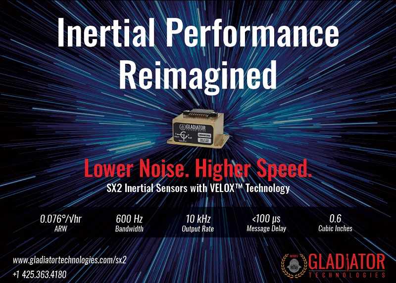
Beyond these core sensing elements, MEMS developers are continuing to work on the surrounding componentry. For instance, as some uncrewed systems operate with higher dynamics, to the point of being dynamically unstable (as highly manoeuvrable aircraft are sometimes designed), higher inertial data update rates are increasingly prized.
Although, to an extent, update rates are limited by the inherent bandwidth of the MEMS structures, optimising downstream signal-processing components such as analogue-to-digital converters and processors can go a long way towards achieving the 2000 Hz update speeds that some integrators are now requesting.
Evolving FOG architectures
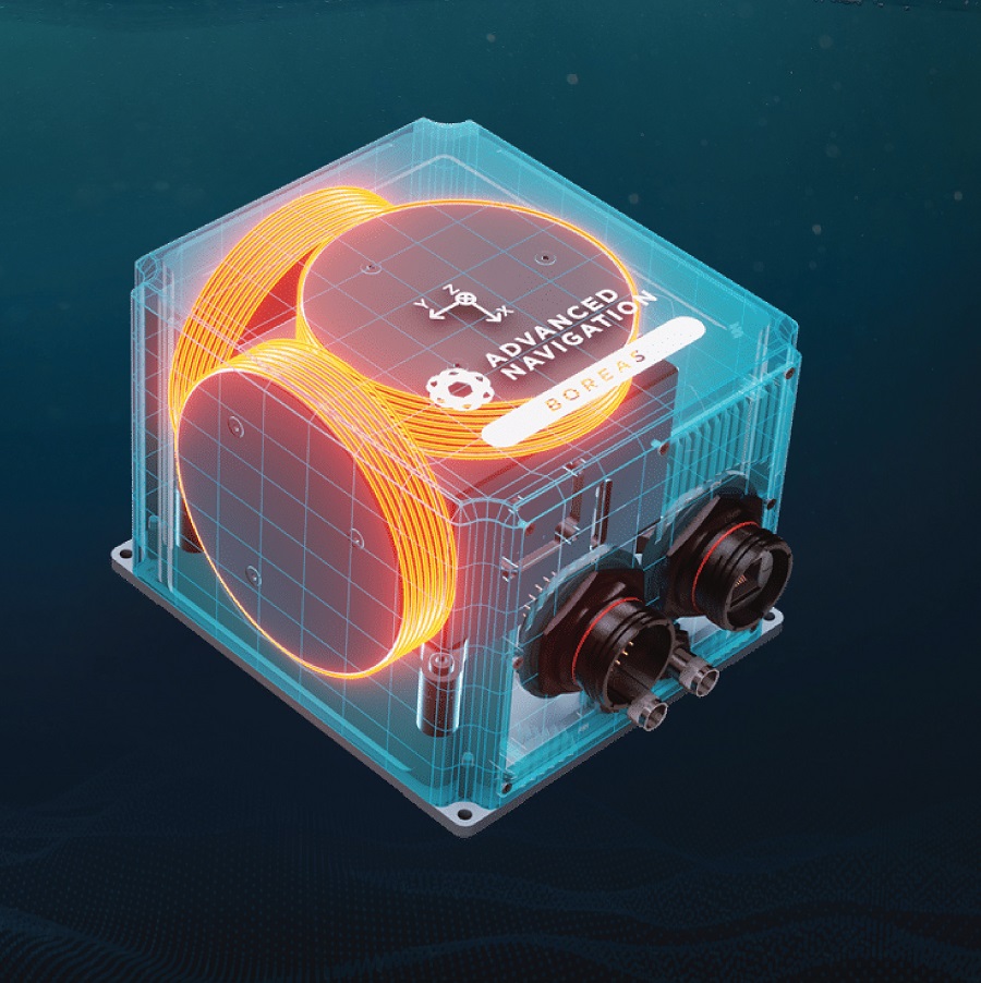
The core internal parts of a FOG consist of an optical fibre that has been turned in a coil many times over, a high-performance light source for beaming down the length of that fibre in opposite directions, and a sensor for detecting the two light beams and any delay between them – which will be induced by and hence proportional to any angular rate imparted on the FOG, both from the host vehicle and the movement of the Earth.
FOGs provide higher performance than MEMS gyros, being larger sensing systems at their core, and solid-state, counting photos moving out of the fibre to sense changes in inertia rather than requiring electromechanical elements to do this. Leading FOG manufacturers will build on the inherently low-bias nature of FOG designs by incorporating advantageous software features, such as the ability to reject common-mode interference and thus enhance bias repeatability.
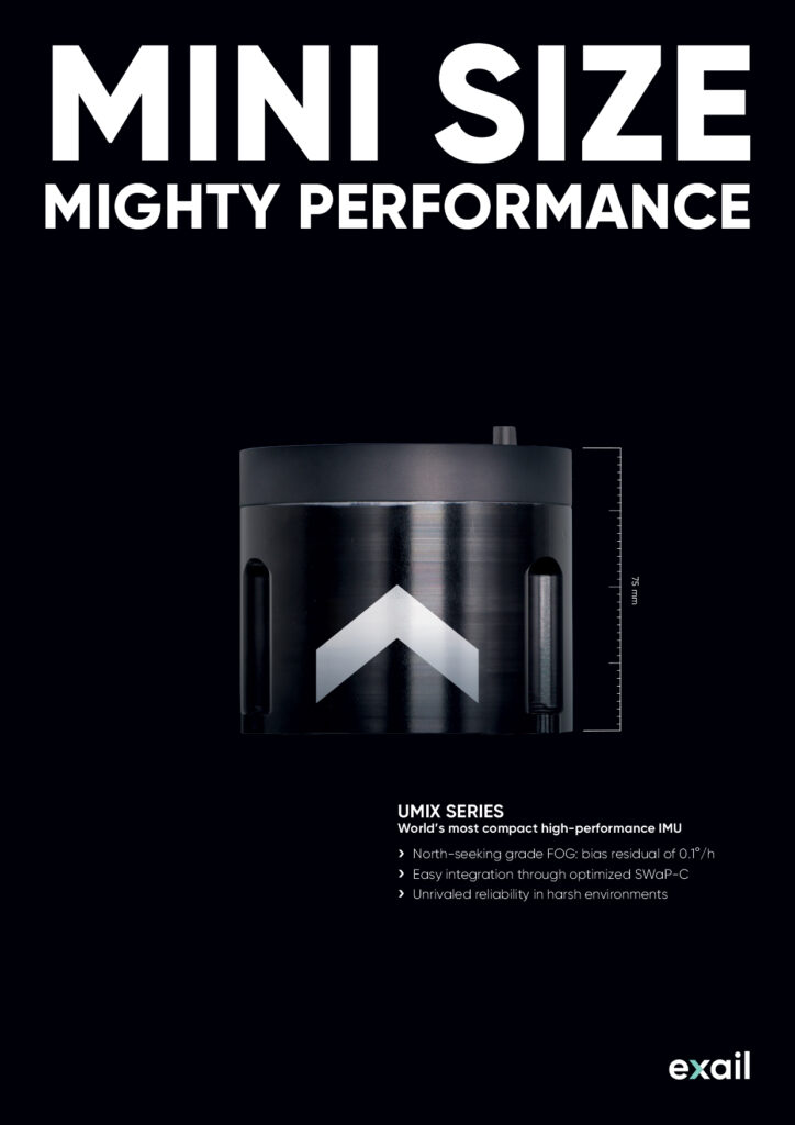
FOG companies are also converging around industry standard IMU form factors of below 10 cm diameter and height (and thus less than half a litre in volume). Within those bounds, such companies seek to engineer the highest-grade IMU they can, and they are gradually vertically integrating their design and production significantly more than MEMS firms tend to.
To push the performance capabilities of today’s FOGs, manufacturers are choosing increasingly thin fibre designs and thinner forms of acrylic polymer coatings (relative to those used five to six years ago) to enable greater lengths of fibre to be wound more tightly into coils of smaller footprints than in past generations without any loss of linear polarisation.
A longer coil means a longer distance for light to travel and hence greater sensitivity to delays indicative of rotational motions. Considerable know-how also goes into ensuring the fibre and its coating can collectively maintain thermal stability across different environments and vibrations, or that effective compensatory measures can be embedded with the software in the device; both MEMS and FOG IMUs being expected to function with minimal error between -40 and 80 C.
Some particularly high-end FOG IMUs are integrating their gyros in a pyramidal shape, rather than the traditional cylindrical or orthogonal arrangement. While the latter inevitably induces some differences in height within a housing, the former ensures all have the same height, and the same geometric orientation and offset relative to the X-, Y- and Z-axes.
This approach was inspired by space applications, and while it is not as volume-efficient as the more industry-standard cylindrical or cubic FOG IMUs, it is more effective at eliminating discrepancies in mechanical sensitivity, by virtue of all three gyros sitting at 120° to the Y-axis, rather than each having a different angle to that axis (and similar factors of that nature).
Further configurations are being conceived to enable higher production volumes and lower costs of FOG IMUs for mass-market applications. One is simply making lower-end devices to fill the perceived middle ground between MEMS and FOG systems; for instance, by using smaller coil sizes of 300-400 m fibre lengths.
FOG-on-chip tech
This leads naturally to smaller FOGs that better fit the space constraints of most uncrewed vehicles. To an extent, this is being achieved through FOG-on-chip (FoC) technology, also referred to as photonic gyro technology, in which the various components of a FOG are integrated into a planar optical chip, rather than involving a PCB and the inside of an electronics enclosure.
A small variety of such FOG products are commercially available, although, arguably, the condensed nature of FoCs brings a far bigger benefit in terms of manufacturing simplicity than the size reduction that one might first notice.
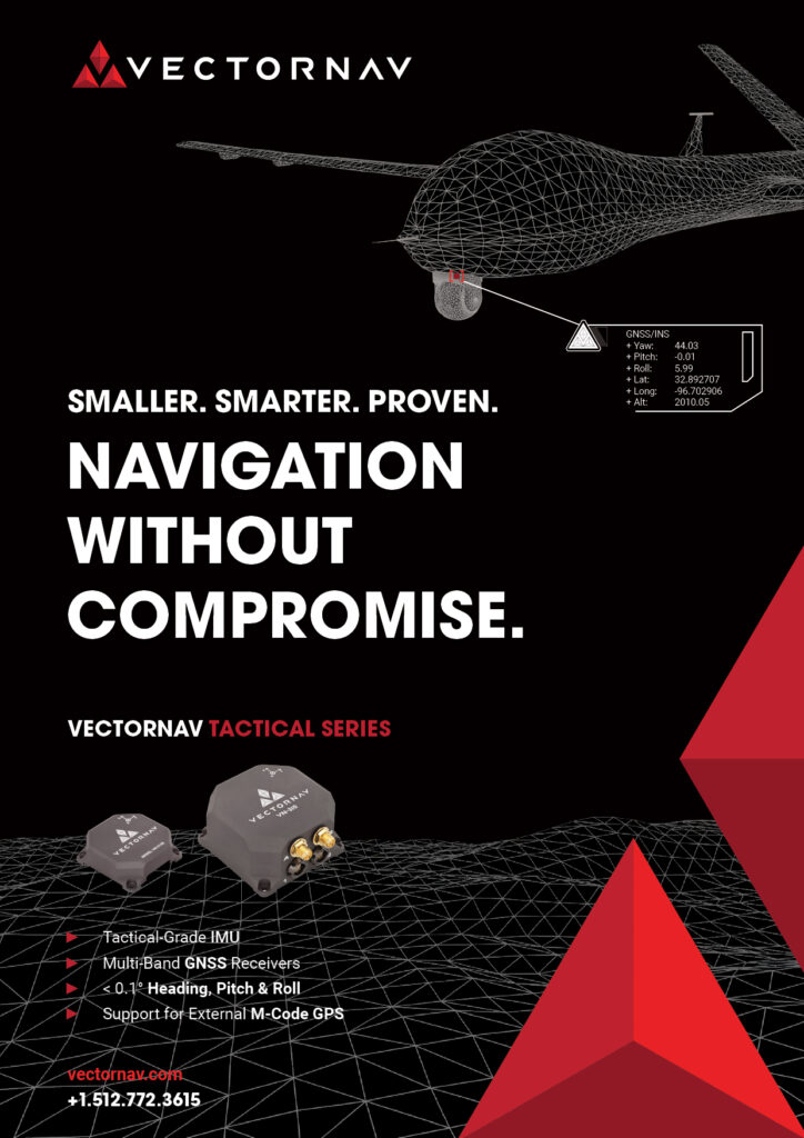
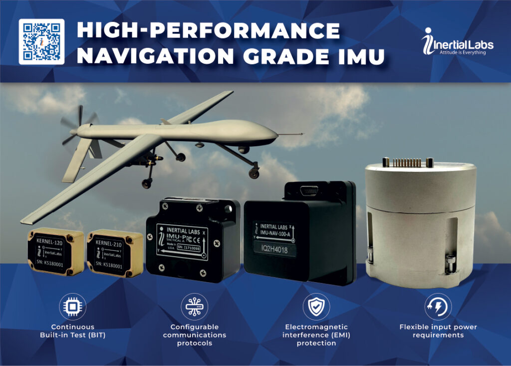
Engineers are also developing higher-end systems to cater for the similarly broadening ecosystem of uncrewed vehicle types. Some readers may be familiar with the industry accepted distinction between tactical-grade IMUs, which require external aiding and are suitable for dead reckoning during brief GNSS outages of up to 10 minutes at a time before drift becomes problematic, and navigation-grade IMUs, which can empower uncrewed vehicles to navigate safely without GNSS for up to an hour at a time and can be used for gyrocompassing (finding true north).
FOG-based systems often meet the standards defining navigation-grade solutions, while MEMS are typically used as tactical-grade devices (as well as industrial-grade systems, which can be relied on for one minute of dead reckoning). But some FOG designers are now eyeing what some refer to as the ‘strategic–’ or ‘sovereign-grade’ level, at which drift and positional error are between a tenth and a hundredth of that in navigation-grade systems.
Usage cases for strategic-grade IMUs are presently few, with just submarines and intercontinental ballistic missiles (ICBMs) as the generally accepted examples, but as more new uncrewed systems go from concept to product, there are likely to be some high-end military UUVs, uncrewed fighter aircraft, autonomous air-freight carriers and other applications requiring strategic-grade navigation systems.
Strategic-grade FOG IMUs are unlikely to be created or demanded in high volume any time soon, although producing them is estimated to require around 5 km of optical fibre, as well as an advanced form of accelerometer known as a quantum gravimeter.
The changing accelerometer
As the name implies, quantum gravimeters are, in essence, extremely sensitive accelerometers based on quantum technology. These can output phenomenally accurate readings at a low rate; fusing that with a traditional accelerometer allows high-bandwidth, high-accuracy acceleration measurements at a rate not yet achieved in any commercially available technology.
For reference, today’s high-end commercially available IMUs can take three to five days to drift by 1 nautical mile, whereas one powered by current prototypes of a quantum gravimeter hybridised with a more standard accelerometer takes around six months to experience such drift.
Access to such systems is currently available albeit with significant restrictions, but some suggest future colonisations of the Moon and Mars will depend on such quantum inertial sensing technology (particularly if autonomous manufacturing facilities pumping out uncrewed robots and satellites are to pave the way for human settlements, as has been suggested to us in past issues).
For such technology to make it to space, however, making IMUs lighter and cheaper comes first, and a critical part of doing that is designing accelerometers with tighter, miniaturised packaging relative to their performance and cost parameters.
This is prompting increased usage of quartz in the production of accelerometers. MEMS made from quartz crystals tend to be bigger than those made from silicon, but do not require tuning for bias sensitivity to input range, as they exhibit the same bias parameters and hence similar performance, whether they have been designed for measurement input ranges of 10 g, 20 g, 30 g or more.
As previously suggested, larger sensing instruments tend to provide higher performance, hence quartz MEMS can offer slightly better bias stability and other parameters over silicon devices of comparable unit cost. Such are the advantages of quartz MEMS over silicon that some silicon MEMS gyroscope manufacturers view quartz as a possible gyro material of the future and are producing prototypes to that end.
Whether of silicon, quartz or another material, it is generally accepted that open-loop accelerometers – in which there is no clear feedback as to whether the output reading has been processed correctly relative to the input value from the sensing element – will be gradually phased out in favour of closed-loop devices. These can use feedback sources such as electrostatic force readings, or more effectively balance the structure of the sensing element around a nominal position to minimise the impact of nonlinearities in the sensor design, and thus achieve more consistently correct data on inertia changes.
MEMS production
Today’s MEMS devices are usually made via photolithography, in much the same way as most integrated circuits. The technique is often leveraged due to its ability to install extremely fine patterns (a few nanometers in size) with close control of the shape and size of objects created across wafers, as well as being able to do so at high speed and low cost.
Such photolithography typically begins with a 100 µm-thick silicon wafer, with a photoresist (a light-sensitive mask) then placed on top of it, for either wet or dry chemical etching to then be used to remove unwanted material, leaving behind only the desired parts of the wafer.
Additionally, metal can be deposited on the surface of the silicon to form the actuators needed to have a variable structure that can move in response to acceleration or rotation, and the transducers which can detect those movements. Together, these steps produce a batch of MEMS accelerometer or gyroscope structures.
New-generation silicon MEMS tend to appear with mass availability every few years, or faster; such is the speed at which MEMS fabricators improve on their older products, while still being able to leverage their existing photolithography and deposition machinery. Next-generation quartz MEMS accelerometers are not yet widely or mass-produced, but this may change over the next few years as new production facilities with laser-etching systems come online.
As a side-effect of quartz-based MEMS being larger, they come with the prospect of being easier to manufacture (without such precise fabrication requirements as silicon), so investing in a quartz MEMS production line comes with a lower capital requirement, all other things being equal.
Complex and exact
Quartz MEMS accelerometers can be produced in various ways, with these sometimes being so complex as to require around 200 steps, but they typically start with a quartz wafer, from which multiple devices can be made.
Chemical lithography and laser etching are among the techniques leveraged by successful manufacturers to etch the exact shape of the MEMS sensing structures. After these are formed and separated into individual units, processing chips can be mounted on their back sides and connected to them via circuitry for turning their capacitive or resistive signals into acceleration data.
After the accelerometer is fabricated, it can be sealed inside a housing, save for an aperture for vacuuming the ambient air – a vacuum environment being highly desirable for ensuring reliable, free movement of the tuning fork inside.
Following selection of MEMS accelerometers and gyros (which can mandate exhaustive testing on bench, simulator, and crewed and uncrewed aircraft to ensure systems perform as their datasheets claim), the systems can be integrated into a circuit board to form an IMU, and that complete system can then be calibrated.
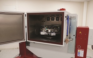
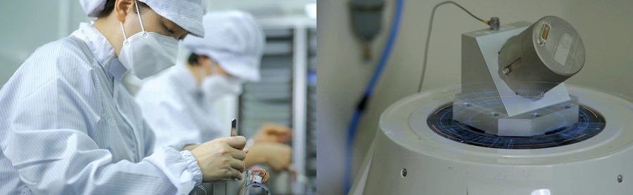
Calibration today, whether for MEMS or FOG devices, is increasingly automated, with the removal of human error essential for consistent quality. A multi-axis thermal chamber is ideal, within which an IMU can be spun or shaken on a rate table at known, controlled accelerations and rotations to examine its output readings, and hence program compensatory subroutines into the Kalman filter.
Automated calibration quality control checks and product functionality tests can then follow to ensure devices conform to standards expected by customers in every respect, from solder correctness to bias over temperature.
While it is rare, some MEMS IMUs are now supplied with their individual calibration reports, enabling customers to see input-to-output discrepancies, scale-factor errors and other biases specific to an IMU to understand what has been calibrated for.
FOG expands
New generations of FOG take at least five years to come out. A principal reason is because engineering and bulk manufacturing a new system can require complete changes to the associated machinery and tooling to ensure fibre can be manipulated, welded and coated differently, and that new integrated optical chips (IOCs) and other associated components can be handled, particularly as these are reaching sizes of 10-40 µm and require more precise equipment.
Manufacturing a FOG begins with extrusion of an optical fibre to the desired thickness and length (which descends from the extrusion point under gravity in most cases), which is followed by the winding of that fibre into a coil. That coil is then coupled with the light source (typically a form of diode), a splitter to ensure light can be sent in opposite directions through the fibre, and the signal detector. The complete coils can then be installed inside the IMU enclosure, along with an accelerometer.
Among the FOG IMU makers seeking to minimise packaging volume, an unusual approach of manufacturing components such as polarisers directly on to the fibre has been developed, instead of performing any splicing (the forced joining of two ends of fibre together, typically by electric arc welding). This involves using heat to shrink the end of a fibre to around one-sixth to one-seventh of its usual thickness, and then growing the polarisation crystal on that shrunken end.
Doing it this way saves on component costs and avoids the performance losses that can result from splices – resulting in a more power-efficient IMU.
Other changes and indeed expansions to production are being undertaken by many leading FOG manufacturers to enable outputs in higher volumes and at lower unit costs, with at least one looking to grow its manufacturing capacity by 10 times.
Doing so requires exhaustive planning, foresight and investment, going down to the very foundations of a production facility. The calibration of FOGs, while technically a similar process to calibrating MEMS, is even more sensitive to vibration; hence, a very large quantity of concrete in the foundation slab (and pinning all of that to bedrock) is imperative for reliable calibration and hence high throughput of FOGs.
Coil winding
Ensuring such foundations minimises the risk that heavy production equipment – such as coil winding machines, composite potting systems for ensuring the coils’ solidness and thermal stability via polyurethane, or three-axis temperature chambers for calibration – will cause vibrations that resonate through to the rest of the facility and the products inside.
The predominant method for coil winding today is quadrupole winding, in which two spools take turns supplying fibre on to a product spool from the centre outwards. As FOGs are highly sensitive to winding nonlinearities, minimising vibration is again critical to successful quadrupole winding, as is minimising error in the winding process.
New generations of production lines are therefore being designed with greater automation for traceability and repeatability, with specialised machinery and machine learning applied to identify any errors that have occurred during winding, potting or other processes.
Polishing of fibre ends, for instance, has traditionally relied on machines activated and operated by human workers, but today this can be fully automated, with consistent results to ensure a flat surface for high-fidelity transmission of light from the source and via a waveguide into the fibre.
As the FoC optical chip typically integrates what would otherwise be 15 to 20 loose components (albeit the coil, laser and detector sit outside of that), much of the production complexity is outsourced to traditional chip-fabrication processes. The mass production of those chips also makes FoCs significantly less pricey than equivalent traditional FOG designs. Future work in FoCs is expected to conceive new designs that incorporate the coil, laser and detector inside the chip – creating, in essence, a microelectromechanical FOG.
External aiding
As indicated, advances in external aiding integrations and sensor fusions are occurring across the uncrewed world at a comparable pace to improvements in MEMS and FOG IMUs themselves.

UGV applications are arguably the fastest growing area of uncrewed systems currently, and as UGVs generally operate with significantly reduced visibility of the sky, compared with UAVs, navigation and mapping systems that go beyond traditional GNSS-IMU integrations are imperative (even two-storey buildings are enough to block some small delivery robots from receiving GNSS signals).
Resorting to higher-end IMUs can be an option if the increased cost and SWaP are no bar, but for many INS manufacturers, navigation software engines (including sensor fusion models and error models) have been developed for decades now to function with MEMS devices, not with FOG IMUs.
The most common approach has been to optimise programming, error modelling, calibration and sometimes MEMS IMU designs to squeeze more performance out of MEMS. Some companies will alternately mount multiple triple-axis MEMS chips (such are their small size nowadays) on a board to average out the data, and come up with higher assurance and precision of inertial readings.
Even more common is the consistency of solutions leveraging non-GNSS aiding sources (as complementary or replacements to the satellite signals), which have been increasingly available over the past few years.
Such sources include ultra-wideband (UWB) systems for indoor positioning, with one trial using UWB sensors throughout a multi-storey car park to enable autonomous valet-parking robotics, as well as Lidar integrated into 3D SLAM arrangements besides Lidar-inertial odometry configurations.
Similarly, cameras are being leveraged and fused with inertial data to output forms of visual odometry across UGVs and UAVs, including situations where a camera was already present on the vehicle, eliminating the need to install significant new hardware onboard.
Integrating IMUs with these new forms of aiding sensors, with their notably different parameters, error models and applicability (depending on the environment) to GNSS can be challenging.
One successful solution is to use a genericising framework as middleware that can conditionally ‘subscribe’ the INS’s processor to data from external aiding sensors, so long as the data format is acceptable and accuracy parameters are also given to enable appropriate weighting in the Kalman filter, along with timestamps and, if applicable, a lever arm (a technical term for the distance between the actual sensing points of the sensors).
Such a framework can enable a wide variety of sensors to be easily read by an INS and incorporated into an autonomous vehicle’s localisation calculations. Hence, this approach is expected to experience significant uptake in the future.
The future
As demand for robust navigation, mapping and geo-pointing rises among professional uncrewed vehicle users across government, business and defence, MEMS manufacturers are expected to double-down on the performance capabilities of their solutions, with a major target being the creation and commercialisation of the first navigation-grade MEMS IMU. Such a device would also be capable of gyrocompassing – another milestone for MEMS, which would put them on a par with FOGs.
FOG developers are working on a wider spectrum of devices, which may blur what were once quite clear lines between MEMS, FOG and RLG applications. This, combined with the variety of INS configurations and external aiding sources growing across the uncrewed world, is likely to spur considerable growth in software algorithms (including open-access solutions) for fusing inertial data and Kalman filters with myriad combinations of other sensors – depending on which combinations make the most sense in the sky, on the road, in water, underground, and everywhere else that uncrewed systems can go.
Acknowledgements
The author would like to thank Walt Johnson and Thomas Bennett of Inertial Sense, Arthur Tua and Olga Pogorelova of Fizoptika, Ian Moore of MicroStrain by Hottinger Bruel & Kjaer, Eric Whitley of Silicon Sensing Systems, David Cunningham and Sébastien Ferrand of Exail, Iain Clarke of OxTS, Xavier Orr of Advanced Navigation and Richard Ryu of Fiberpro for their help in researching this article.
UPCOMING EVENTS


