


Aergility ATLIS
(Images courtesy of Aergility)
Freight agent
Cost and energy efficiency are the watchwords for this cargo-carrying UAV, thanks to a technology called managed autorotation. Rory Jackson reports
As reported in the past in this publication, the traditional helicopter configuration has long left something to be desired among military and civilian end-users. Commonly cited weaknesses include the maintenance costs of their swashplate and other moving parts, the vulnerability of the tail rotor, and a tendency towards mechanical failures in mid-flight.
Meanwhile, well-established alternatives have failed to establish themselves. For example, autogyros are not actually capable of VTOL but fly through autorotation, spinning and providing lift only passively as the air flows through them. They are also not especially energy efficient, owing to the drag and back- forces generated during autorotation.
Against this backdrop, Jim Vander Mey – the CEO and founder of UAV manufacturer Aergility – was motivated to design a VTOL system that is simpler and safer than a helicopter, and more efficient and capable than an autogyro.
He examined how autogyro technology might be used towards that goal, eventually coming up with a form of flight and power control that Aergility calls “managed autorotation” (MAT).
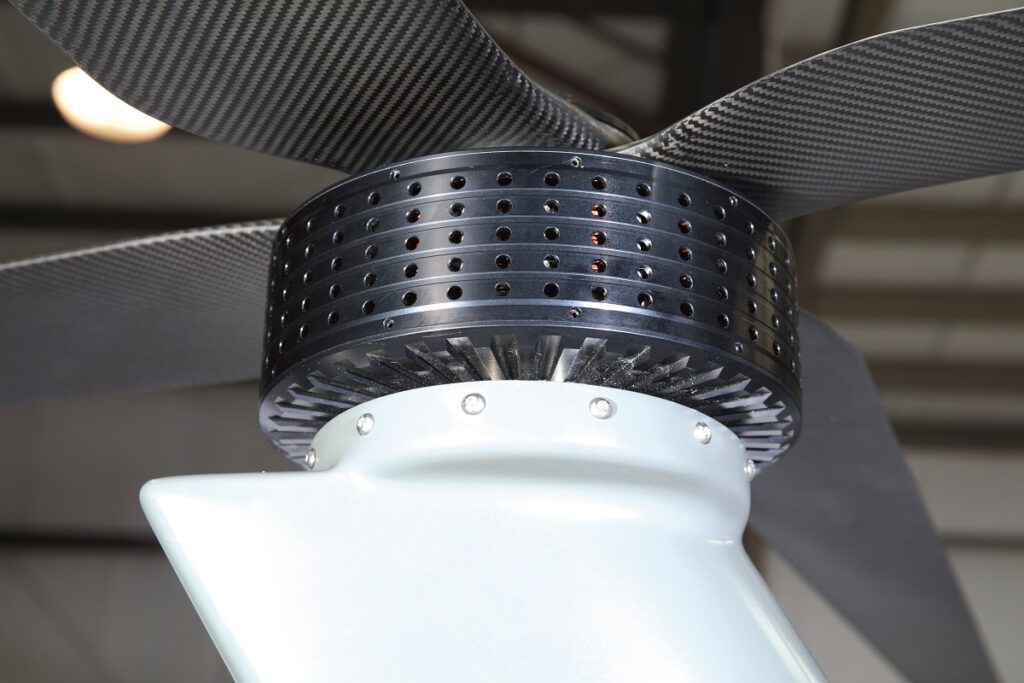
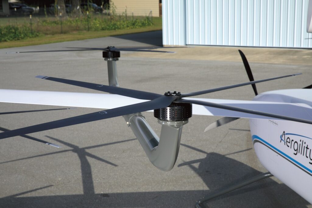
An aircraft that flies using MAT uses multiple vertically disposed rotors to perform all the roll, pitch and yaw movements. The rotors are spun by electric motors that incorporate fixed-pitch propellers and no swashplate, meaning no notably vulnerable points of failure.
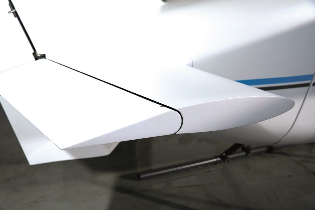
During cruise, around half the lift from MAT is achieved using fixed wings, with the rotors mounted near the wingtips and on booms installed along the length of either wing; the rest of the lift comes from the rotors, and forward motion comes from a powered pusher or tractor propeller. That enables an autorotation pitch very close to 0º, and the inherent balancing of the craft’s rotors allow it to fly with whatever pitch attitude is most efficient, eliminating the typical inefficiencies of autogyro operation.
Also, as the aircraft changes attitude or is cruising, any of the rotors (while unpowered for autorotation) can also be used as generators. As the air spins them, the motion is converted into electricity to recharge the onboard batteries: essentially it’s an aerial form of regenerative braking.
In short, the MAT-powered aircraft takes off and lands using its electric motors like a multi-rotor, flies using the air blowing through its unpowered rotors like an autogyro (with help from its fixed wings like a plane) and performs attitude changes by occasionally powering its rotors.
“To develop my concept for managed autorotation, I first built a custom flight controller in Python in order to interface with X-Plane’s flight simulator software; that’s where I originated the flight controller that I then filed a patent on in August 2014,” Vander Mey recounts.
Having affirmed that his flight controller architecture worked, he showed it to aviation expert Larry Yonge, who liked what he saw. The two then formed Aergility in May 2015 to develop the concept into a product.
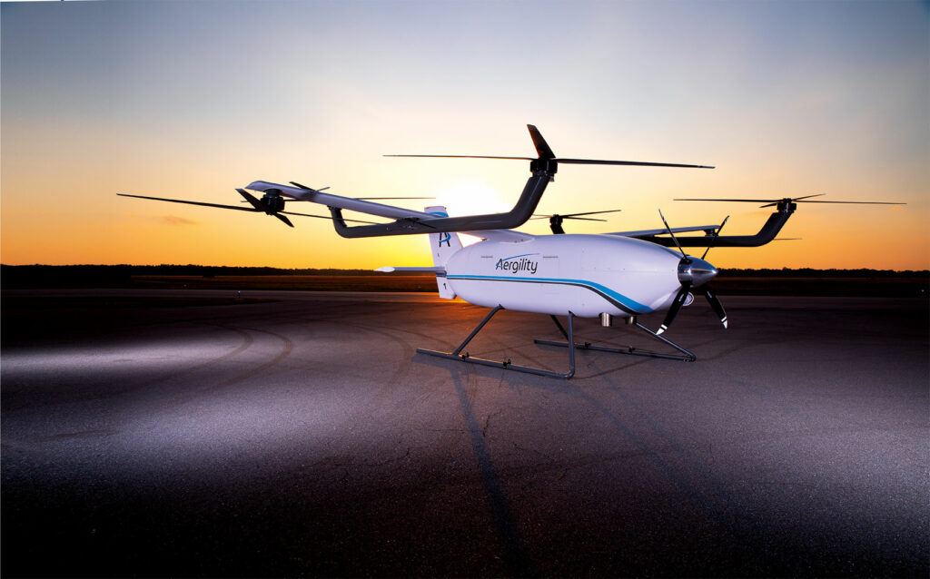
That product is now the ATLIS UAV, a 1550 lb (703 kg) MTOW hybrid-electric aircraft designed as a cost- and energy-efficient autonomous air freight solution. It runs on a microturbine engine and carries up to 295 kg of fuel and payload, so if for instance around 200-205 kg of cargo and 90-95 kg of fuel are loaded, it can deliver that cargo up to 450 miles (724 km) away.

If an optional auxiliary fuel tank is installed, taking the UAV’s fuel capacity from 94.6 to 125 litres, that range rises to nearly 966 km – and of course, it will take off and land vertically in any space accommodating its 10.15 m wingspan. It cruises at 193 kph and has a maximum flight endurance of 4.5 hours through its MAT and turboprop-hybrid powertrain, all the parts for which are mounted about what is currently a 40 cu ft (1.13 m3) cargo container.
Iterative development
Between 2015 and 2017, Yonge and Vander Mey carried out some key groundwork. “Just one of the many problems we needed to solve early on was optimising the rotor, not only for low-drag autorotation performance in forward flight, but also reasonable efficiency during hover,” Yonge (now VP of r&d at Aergility) recounts.
“Jim would primarily do CFD simulations, while I developed a blade element analysis system that gauged performance while giving insight into mechanical properties. Both of us used X-Plane simulations and considered different aircraft configurations.”
In 2018, Aergility was approached by a large (unnamed) organisation which had ascertained that the company’s proposed aircraft was a potential solution to some key use cases in its business. “They wanted to invest in and eventually purchase our future aircraft, on the condition that we could first prove that our solution worked in real-world tests,” Vander Mey says.
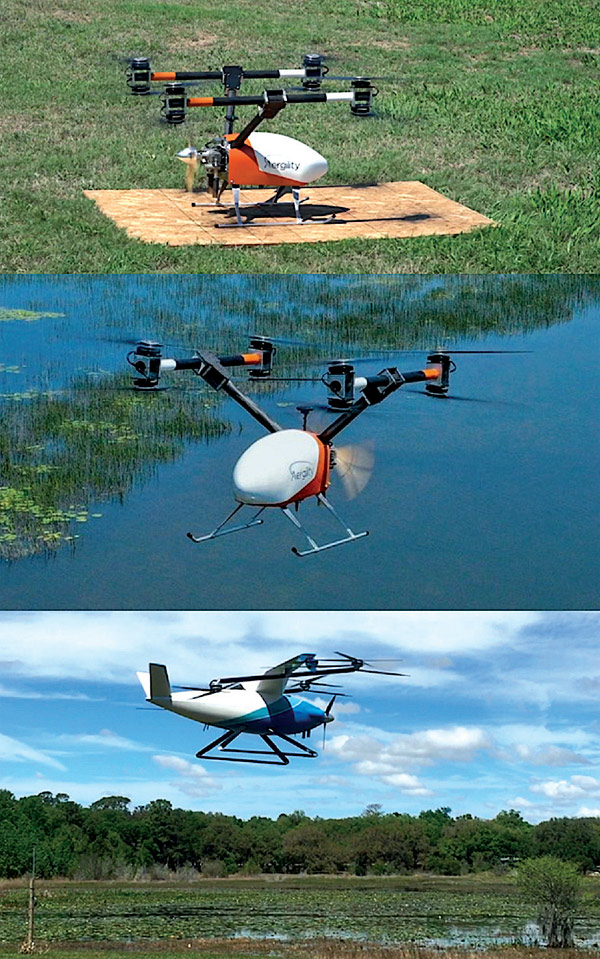
Aergility had developed a quarter-scale prototype in 2017, which was tested from 2018 to 2020. This was an X-8 coaxial octocopter with a push-propeller, but no wings or cargo hold yet.
“Finding suitable e-motors was challenging, but that paled in comparison to motor controllers,” Yonge says. “At the time, most ESCs were geared towards drones running at the top of their motors’ rpm and thrust curves, but we needed fine control over both power and speed, even at near-zero thrust and when the motor was generating electricity.
“So initially on the Gen 1 prototype, we just used an open-source ESC that allowed us to do all the changes and tests we wanted. We also built a coaxial motor test stand where we could gauge the motor pairings and ESCs at different states of hover.”
Even before the Gen 1, Aergility built its version of an ‘artificial wind tunnel’, which consisted of a structure on the back of a pick-up truck reminiscent of a multi-rotor airframe. Driving the truck down roads near the company simulated the rush of air in flight, and enabled testing of how the rotors and ESCs performed in forward flight and autorotation at different pitch attitudes, ahead of the first test flights in February 2018.
Through its 2 years of real-world trials, the core MAT concept was proven out, and key areas for future improvements were identified, such as the potential for interference between rotors and how the aircraft might be reconfigured to mitigate that and enhance performance.
“Those trials gave that big company the data to convince them we’d either met or exceeded their expectations, so in 2020 they became our silent partner and funded us to develop the Gen 2 and then the current Gen 3,” Vander Mey says.
The Gen 2 prototype followed in 2020, fitted with six staggered rotors to resolve the interference, a tractor propeller, a small-chord wing for greater cruise efficiency and a vee-tail for flight trim.
“Gen 2 was also quarter-scale, albeit with a much more efficient design, so much so that its test regimen led directly to what we unveiled in early 2022 at AUVSI Xponential, which we call our full-scale Gen 3 ATLIS, the version we have now,” Yonge says.
“Size comparisons aside, there’s little fundamental design difference between the Gen 2 and Gen 3. The main things are that the back rotors are higher for the loading crew’s safety, and the fuselage is better shaped for cargo boxes.”
From 2020 to ’21, Aergility worked on detailed internal structural designs to ensure the Gen 3’s ability to handle loads, vibrations, bending moments and other forces. At the same time, it developed a network of consultants, contractors and suppliers, many of whom were selected for their ability to custom-design high-end components for the ATLIS’ unique flight behaviours and configuration; Aergility notes that the rotors, airframe, flight controller and ESCs were among the most important.
Considerable airframe optimisation was performed by Airboss Aviation Group, which Yonge notes provided structural design and analyses for ensuring that the hull pieces and materials met all the safety margins for loadings. Composites Universal Group (CUG) began building that design in October 2021, which concluded in April 2022.
“CUG has great experience and success in realising unconventional aircraft designs, even in the new eVTOL world,” Yonge says. “They built the Airbus Vahana, and the Archer Aviation prototypes, for example.
“Meanwhile, on the avionics side of things, we’d used open-source Pixhawk controllers in the Gen 1 and Gen 2, but we’ve since looked to Embention for our professional-grade autopilot, and Advanced Power Drives [APD] to design and make the ESCs we need.”
Vander Mey adds, “Being based in Florida, we have access to great people for aerospace engineering and consulting, but if you want best-in-class expertise or aircraft subsystems, you’ll rarely find them all next door. For example, we engaged Aerospace Control Dynamics to ensure the theoretical basis and practical robustness of our flight control algorithms. For our UAV to offer the desired level of efficiency and performance, we’ve sourced consulting engineers and vendors from across America, Europe, Asia and Australia.”
In addition to its main investor and future customer, Aergility sees three primary uses for the ATLIS. The first is humanitarian aid, which is currently delivered by dangerous and uneconomical means such as crewed helicopters and RIBs, and where the infrastructure for such vehicles and crews is often rendered unsafe by disasters. A UAS could therefore perform such tasks with greater safety and hence lower expected human, mechanical and financial costs.
For similar reasons, military missions – especially resupplying forward operating bases – are also seen as key, particularly since any ground or air vehicles with crew on board must have upgraded armour, the cost of which is so prohibitive that frontline soldiers in Afghanistan and Iraq for instance eventually stopped receiving mail from home owing to the huge expense of delivery.
By contrast, commercial logistics in North America and Europe are not seen as near-term key markets because of tight airspace regulations and well-established road and rail freight networks. Such networks do not yet exist in much of Africa, however, and will probably never exist in island nations such as Indonesia or the Philippines, making the ATLIS a valuable potential proposition for commercial organisations there.
Inside the ATLIS
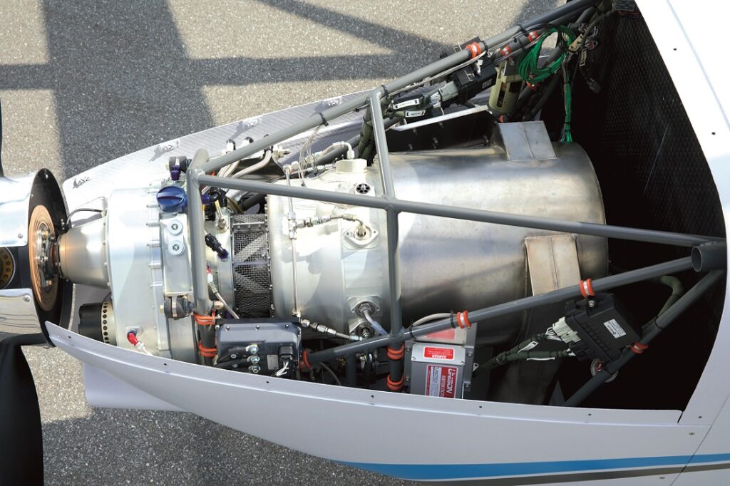
Between the six vertically disposed rotors, two landing struts and a single microturbine engine and variable-pitch propeller (VPP) is Embention’s Veronte 4X flight controller, in the ceiling above the cargo bay, in front of the wing but behind the firewall.
“The 4X autopilot has three redundant flight controllers, each with two GNSS inputs, so we have two antennas per flight controller, and the pairs are mounted as far apart as possible from each other, in front of and behind the wing, away from potential interference from the rotors,” Yonge says.
“That ensures each flight controller gets an independent reading of true heading, using GNSS and not just our magnetometer. And six motor controllers – one per motor – are integrated in the ceiling behind the wings, roughly co-located with the antennas.”
The wings are ‘wet’, in that fuel runs inside them from fuel connectors on the fuselage. These feed into a main belly tank near the landing struts, then goes to the engine. Behind the belly tank are the batteries, and between the tank and the firewall is a radar altimeter for automatic take-off, landing and safety-critical height measurements.
Also, a video camera is installed atop the tail to give a pilot’s perspective of the UAV, for further real-time flight safety (autonomously through computer vision, and remotely piloted). The avionics also incorporate a terrestrial transceiver and a satellite transceiver for ensuring consistent real-time telemetry; this is mounted in the ceiling forward of the wing. Elsewhere in the hull are the magnetometer (from Honeywell) and an ADS-B transponder.
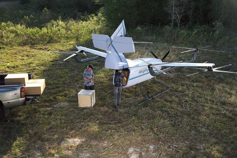
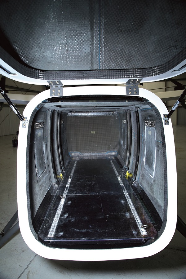
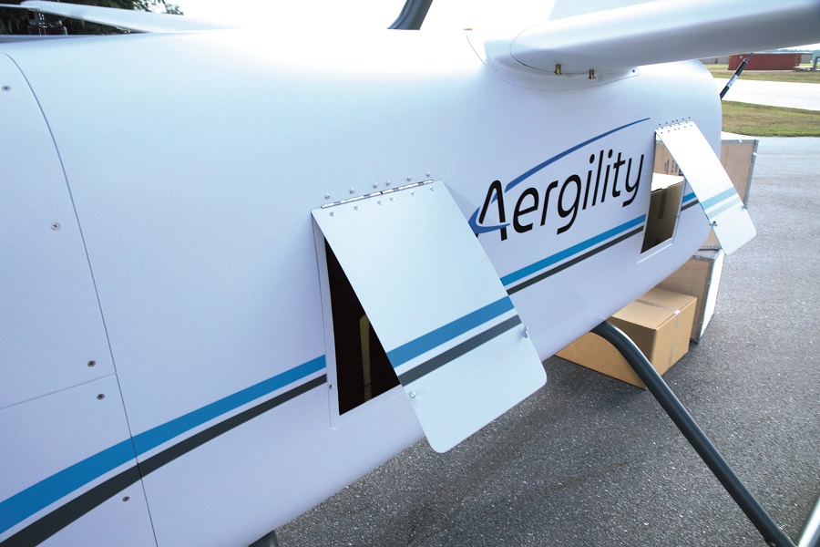
The cargo hatch at the rear is manually operated. The tail latches onto the undercarriage, and lifts after being unlatched, with gas struts for assisted lifting. Latched side doors also open as needed for parcels.
The cargo bay is designed for VDA 4500 standard containers, also called EURO containers or KLT boxes optionally loaded on a 1200 x 800 mm EURO pallet [or EPAL]; two EPALS or four of the EURO 800 mm x 600 mm containers will fit end-to-end inside the production cargo bay.
For flight safety, the ATLIS will not take off with a payload whose centre of gravity (CoG) is outside allowable ranges. To simplify loading, Aergility is also considering using a CoG-balanced pod that could be loaded and slid into the cargo bay on rails to secure it or even auto-latch it in place, with smart carts to assist loading and load cells to confirm that the CoG and weight distribution are acceptable before loading.
MAT dynamics
In addition to managing the ATLIS’ attitude control, the various electric rotors are also key to the net power consumption (or generation).
“When the UAV tilts back a little, it’s in full autorotation,” Yonge explains. “At that point, you can put the nose down a bit and put just a little power into the motors to maintain their rpm, either directly from the battery or indirectly from the engine/generator. That gives you the ATLIS’ most efficient flight mode.
“You can tilt the aircraft further back, to have the wind drive the rotors harder and get the motors generating net positive power for the battery. That recharges the electric power without engaging the engine/generator, but it is more efficient to use the small engine-mounted generator to recharge the batteries.
“Rotor braking is a fallback mode, should the power from the generator be unavailable. Our core competencies are built on the necessary control loops for managing attitude and power simultaneously through this motor network.”
This system thus enables the ATLIS to fly with net-zero electrical consumption over the course of flight. For example, if the UAV banks right, the power management system powers the left rotors to lift the left wing, and depowers the right rotors to dip the right wing. In this instance, the three right-hand rotors are past autorotation, and are generating electric power, but the left-hand motors are consuming no more power than that being generated by their counterparts.
“It’s the same across pitch and yaw,” Yonge says. “If you don’t attempt any unnecessarily strong manoeuvres, you can fly, climb and descend at zero electrical power, although fuel is of course being burned by the propulsion engine.
“Perhaps most significantly for safety purposes, if the engine should ever fail, or human error causes you to run out of fuel, the ATLIS can glide on its wings like an aeroplane, with the rotors autorotating all the while thanks to the flight controller keeping the pitch attitude correct for the descent angle of glide.
“It’ll consume no power until it needs to land vertically, at which moment its battery reserves should be either preserved or replenished enough that the rotors can be powered on to accomplish a gentle emergency landing that keeps the cargo undamaged.”
Another key aspect concerns the point of VTOL transitioning, which can be a headache for engineers to program smoothly into a flight controller’s logic. Fortunately, the ATLIS does not technically have a transition state; it takes off with its rotors at full power, the forward propulsion engine is applied, and the rotors are gradually powered down as the UAV moves forwards (as per a helicopter’s flight behaviour).
As it moves forwards, the rotor power continues to decrease, and the flight controller manages that declining curve to autorotate at low or high speeds depending on aircraft pitch.
“It’s basically all one state, instead of being two separate states of flight – one vertical, the other horizontal – so we avoid that perennial tricky transition point sticking between them and all the difficulties of tiltrotors or hard power switching that comes with it,” Vander Mey explains.
“It’s rather a smooth transition ‘curve’ as the power going to the motors decreases. For instance, if you wanted to fly slowly but not in autorotation, the rotors would need to consume a small amount of power.”
Flight control
Transmissions between the flight control surfaces – the six e-motors as well as an elevator and rudder at the tail – are relayed over CAN bus at a rate of about 500 kbit/s. Although the MAT’s processes sound complex, the actual amount of data needed for control is small – one 8-byte packet can control three ESCs. Comms with the engine FADEC are also carried on this network.
“We prefer to keep things simple,” Vander Mey says. “We have an elevator and rudder now, but we anticipate that when we go to scale production, we’ll probably just have a horizontal trim elevator, because the control is being accomplished fully with just the rotors.”
Yonge adds, “The rudder is operated by a Hitec commercial servo, and a slow linear actuator from Thompson works the elevator. It’s slow because the elevator is mainly there for pitch trim, to balance the power being used by the front and rear rotors if we have an unbalanced CoG owing to how the cargo has been loaded.
“Both servos run on the CAN bus, as does the BMS, and the latter connects directly to the flight controller for real-time monitoring of the power and battery status to adjust aircraft pitch so that zero net power is maintained. Beyond the CAN, there’s also a dedicated serial bus for the magnetometer and some avionics.”
While a conventional multi-rotor might have three control loops for governing roll, pitch and yaw, the MAT’s flight logic is built on six. Its fourth manages horizontal airspeed, running from hover to forward flight, and is achieved largely through the propulsion engine, while the fifth is an altitude control loop that governs the rpm of the rotors.
“In forward flight, that altitude loop still mainly just selects rotor speeds, but it also targets some minor pitch adjustments when climbing or descending,” Yonge explains.
“The sixth control loop is for power management. That primarily targets pitch attitude in forward flight to achieve the desired net electric power consumption or generation from the motors. Technically though there are seven control loops in total, as all multi-rotors have something of an extra loop that ensures roll and yaw are coordinated during forward flight.”
Collectively the loops are key to the ‘transitionless’ nature of the ATLIS’ flight. It behaves virtually identically to a multi-rotor at take-off, with the altitude loop defining the thrust and rate of climb, and once the target altitude is reached, the speed control loop becomes active and powers the turboprop (often with a sharp acceleration curve).
As the ATLIS accelerates, the altitude loop reduces the rotor rpm, because less and less active rotor thrust is needed to support lift. “That would happen even if no wings were there, but as we’ve said, the ATLIS’ wing carries half the load,” Yonge says.
Once in cruise (or even mid-climb and mid-descent later on), the power management loop goes from targeting a flat pitch attitude to targeting the required pitch for the desired battery recharge, as energy is consumed through roll and yaw for instance via those respective control loops.
“All these loops execute pretty much automatically, and there are clearly defined targets and boundaries with no risk of conflict between them – it’s not like a tiltrotor, where there are lots of complexity and potential for fatal errors,” Yonge says.
Electric power
Energy is stored across three redundant 400 V lithium-polymer battery packs, each with nine 12S modules and a capacity of 10 Ah for around 12 kWh total maximum onboard battery energy to enable extended initial flight testing.
Aergility plans to lower that by two-thirds for the production version, once it is confident that the ATLIS can fly safely without the need for such extensive and heavy power reserves. A series of custom BMS boards made in-house manages the constant discharging, recharging and cell balancing inherent in MAT, and there is one BMS for each pack. The entire production battery system with the three redundant battery packs will weigh 125 lb.
Each pack also powers two rotors – one powers the front-right and rear-left, one for the front-left and rear-right, and one for the two middle ones. This ensures that control is maintained over roll and pitch attitudes for safe landing if one pack should fail, and in the event of a bird strike to a rotor, switching off the associated pack will similarly depower both the damaged rotor and its partner.
“When it came to designing the rotors, we realised we could sacrifice some hover performance in favour of forward flight optimisation, because we don’t actually spend much time in hover,” Yonge says. “Also, the e-motors had to be very efficient for take-off yet work well at near-zero power from low rpm – most motors can do that if cogging isn’t an issue.”
As mentioned, the motor controller was a bigger challenge. Aergility needed a full four-quadrant ESC with speed control and forward and reverse rotation. While doing wind tunnel testing (at Lockheed Martin’s facilities) the company found that the motors would sometimes need to spin backwards to avoid producing excess thrust, so efficient operation over the full range of positive to negative rpm and power was key.
“APD’s motor controllers use SiC transistors, which have very low switching losses and hence extremely high efficiency – around 99% in fact – when the ATLIS is in hover,” Yonge comments.
“When in forward flight, at near 0 W net consumption, we still need really efficient power transistors switching power back and forth between the motors and our 400-450 V batteries. By comparison, typical FETs would be wasting quite a bit of power through that switching.”
SiC’s efficiency also reduces the amount of heat that has to be dissipated compared with FET-based ESCs; Aergility estimates a 75% reduction. “The ESCs on our test rigs from 2015-22 would be covered in huge heat sinks because of the dissipation needed for the switching,” Vander Mey says. “Using SiC means we don’t need sophisticated cooling arrangements for the 3 minutes we spend hovering, during which we might otherwise produce several thousand watts of heat.”
The electric motors are custom-designed versions of Emrax’s 228, built around tapered needle bearings to withstand the unusual moments of MAT flight and hence ensure the motors can still have MTBFs greater than 10,000 hours. Aergility is also collaborating with an undisclosed supplier on a high IP-rated e-motor design for flights in extreme weather.
The Emrax 228 produces 109 kW peak and 60 kW continuously, although the ATLIS does not require such high power or the associated rpm; instead, the high efficiency (96% peak, 94-95% during the ATLIS’ hover) is cited as a primary appeal.
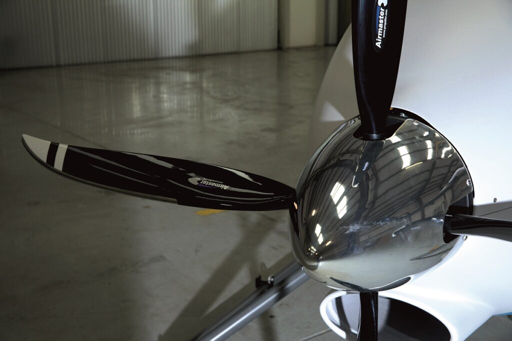
Turbo propulsion
Power for forward propulsion comes from a Turbotech TP-R90 (explored in detail in UST 31, April/May 2020). It is a 90 kW, 80 kg micro-turboprop built around a heat exchanger composed of microtubes that recuperates the otherwise wasted exhaust gas heat to preheat intake air.
That air thus requires less fuel than usual for combustion and power, roughly doubling the overall fuel efficiency (to around 19 litres/hour) compared with regular microturbine designs. This, and lowering both the emissions and noise, made it ideal for Aergility’s solution.
“It was too challenging to find a reciprocating engine that could run on heavy fuel and still provide the power we wanted, and the rotary engines we looked at were too expensive and didn’t have long enough TBOs,” Vander Mey says.
“Not only does Turbotech’s engine run on widely available jet fuels and diesels, it can run smoothly on a range of sustainable fuels, like biofuels and eventually hydrogen, which is going to become more and more important in many areas. Its 3000-hour TBO is great too – it’s not a cheap engine, but that kind of runtime pays for itself after a short while.”
Yonge adds, “Also, the heat recuperation means it maintains the fuel efficiency of a reciprocating engine at low altitudes, otherwise we’d have to carry much more fuel, which would eat into our payload capacity.”
For added propulsive efficiency, Turbotech packages Airmaster variable-pitch propellers as standard with its turboprops, enabling the ATLIS to optimise its forward prop blade angle for whatever airspeed is targeted.
“Also, the TP-R90’s starter/generator is a 24-28 V AC system, so our BMSs have built-in voltage converters to take the generator output and turn it into a 50 V DC supply that can be used to charge our cells, while the BMSs also control the load imparted by the cells on the generator so as not to overload it,” Yonge says.
Avionics
Choosing the Veronte 4X came down to a few essential criteria. One was flight redundancy, and as mentioned the 4X is triple-redundant and was developed under the DO-178C and DO-254 safety standards, making it certifiable within any aircraft that follows them.
“As a flight control system, MAT is unique and not easily adaptable, so we needed a lot of configurability,” Yonge adds. “Veronte is not quite open source, but it is open in the user-configuration sense.
“In our scale aircraft flight tests the Veronte 1X actually suffices – the 4X has three of those autopilots connected with an arbiter. But either way, you have great access to flight control laws: there’s a dual CAN bus on it that gives us hefty control, monitoring and redundancy over our motor controllers, and in addition the cost was acceptable.”

Vander Mey says, “A lot of current autopilots are designed as if they’re trying to do all the work for you, whereas the Veronte has something of a scripting approach that allows us the flexibility to build the autopilot we actually want, without having to write a lot of new code. Embention’s architecture is therefore very amenable to our flight controls, and that made them the most practical choice.”
Much of the avionics selections – such as the IMUs, two pitot tubes (one on each wingtip beyond the interference of the rotors), satellite transceiver, RTK-GNSS receivers, and antennas – came pre-selected as part of the Veronte 4X package. On the other hand, a COTS video camera and radar altimeter were Aergility’s own choices.
The altimeter is a US-D1 from Ainstein, which consumes 2 W to operate at a frequency of 24 GHz over a 190 MHz bandwidth. It weighs 110 g and works from heights of 50 m down to 0.5 m, giving altitude measurements precise to 4 cm when flying higher than 1 m (6 cm precision at altitudes below 1 m) over a 43 x 30º FoV.
“We also plan to include Lidars for obstacle sensing and avoidance, for edge cases that could make use of that,” Yonge notes.
Airframe construction
Most of the aerodynamics in the current ATLIS configuration are the result of Aergility’s own r&d. The bulk of CFD was simulated in Siemens’ Star CCM+ software, with Dassault’s SolidWorks used for principal CAD design work. “We used a couple of FEA packages, with CUG and Airboss having their own preferences, but they also used SolidWorks quite a bit too,” Vander Mey says.
When the company began working with CUG and Airboss, the latter two iterated the structure to better adapt it for variables that came up between 2020 and ’22, such as the real-world effects of cargo handling and engine integration.
“We gave them the configuration, the booms, rotor locations, the tail and wings, and talked to them about how to shave weight and drag,” Yonge says.
“Airboss’ most significant changes were in utilitarian reshaping of the fuselage to better fit the cargo bay and be less heavy, which is why we have a more rectangular and elongated shape in the Gen 3 than the Gen 2.
“They also made a number of tweaks to improve the internal wing structure, like the spars, ribs and wet sections. They optimised the fuselage’s ring bulkheads and firewall too, as well as the hinge mechanism and other aspects of the tail.”
The hull is mostly carbon composite for strength and rigidity as well as low weight, although fibreglass composite is used in a few areas to provide RF transparency for the antennas, transceivers and radar altimeter, none of which sit outside the body and generate parasitic drag. The landing struts are steel and aluminium for maximised load bearing.
“The hull was built largely using prepregs, and a combination of unidirectional and other weaves were applied for handling different forces throughout flight,” Yonge notes. “CUG and Airboss were key to that.”
Vander Mey also notes that CUG and Airboss worked together to ensure that the design evolved not only for effective operation, but also for efficient manufacturing and road transportability. A key requirement of the ATLIS’ construction was that it had to be easily disassembled, moved by van or truck, then reassembled. The wings and booms therefore had to be removable, and all the parts had to fit in a 20 ft standard container, and be no wider altogether than 8 ft.
“The booms attach to the wings via inverted saddles, mechanically secured by four bolts and with electrical connectors inside the saddles,” Yonge explains.
“As for the wings, there are spars that cross each other inside the fuselage – a main spar and a rear spar – with two bolts for each spar. The four bolts are removed to slide the wing spars out of the spar box. The wings with the rotors would go in the sides of the container, the booms would hang from the ceiling, and the fuselage and spars would go underneath.”
Future markets
In addition to humanitarian, military and commercial logistics operations, numerous other markets could benefit from using the ATLIS.
Africa in particular has around 400,000 villages that can’t rely on road deliveries, but just as more and more African economies are skipping wired telecoms networks and going straight to wireless technologies, people are now watching how Africa is poised to skip crewed logistics and move to uncrewed systems,” Vander Mey observes.
Aergility reports interest from other potential customers watching the UAV’s development. These include remote hotel resorts that need aerial deliveries, repair equipment drops for oil rigs and mines, medical logistics where road and rail delays can’t be afforded, and various use cases with the UN World Food Programme where air operators are increasingly constrained by high fuel prices and other costs.
And although it is not currently a priority, the company adds that there are paths towards reconfiguring the ATLIS for agricultural spray or firefighting.
In addition to continued work on design and testing, and discussions with potential customers to refine the ATLIS’ product specifications or enhancements, there is still work to be done to ensure it meets certification requirements and in preparing a production manufacturing capability.
First steps along those lines were accomplished when Aergility recently acquired a facility in Florida. It will be the base for full-scale flight testing and should enable commercial production to start in 2025.
- Specifications
- ATLIS UAV
- Dimensions: 10.15 x 4.66 x 2.16 m
- MTOW: 703 kg, Empty weight: 408 kg
- Carrying capacity: 295 kg, (fuel and payload)
- Cargo space: prototype 40 cu ft (1.13 m3); production 67 cu ft
- Operating range: 724.2 km, (965.6 km with auxiliary fuel tank)
- Operating endurance: 4.5 hours
- Cruising speed: 193 kph
- Maximum airspeed: 225 kph
- Maximum engine power: 90 kW (122 bhp)
- ATLIS UAV
- Some key suppliers
- Airframe manufacture: Composites Universal Group
- Structural design and optimisation: Airboss Aviation Group
- Flight control laws: Aerospace Control Dynamics
- CFD: Siemens, CAD: Dassault Systemes
- Flight simulation: X-Plane
- Autopilot: Embention
- Magnetometer: Honeywell
- Radar altimeter: Ainstein
- Elevator servos: Thompson
- Rudder servos: Hitec
- Turboprop engine: Turbotech
- Electric motors: Emrax
- Motor controllers: Advanced Power Drives
- Variable-pitch propellers: Airmaster
- Rotor propellers: Xoar
- Rotor propellers: Mejzlik
UPCOMING EVENTS


