


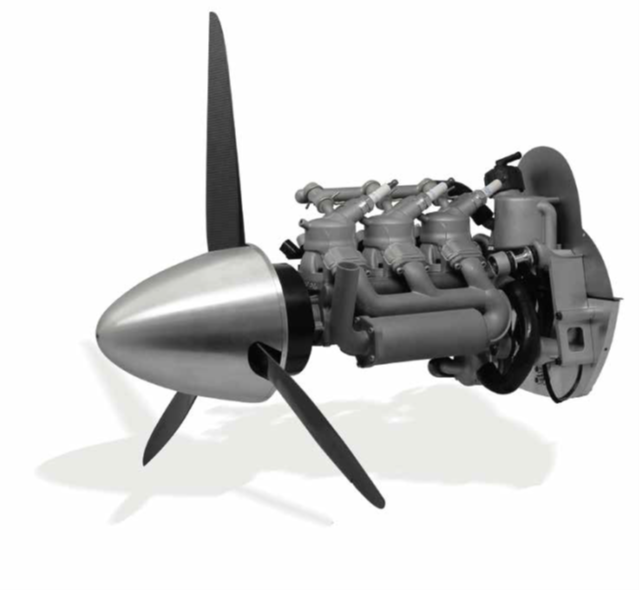
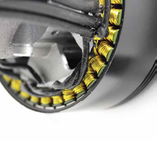
Cobra Aero A99H
(Images courtesy of Cobra Aero)
Three-pot
Rory Jackson talks to the developers of this inline three-cylinder engine about its advantages over other designs
In UST 12 (February/March 2017) we featured the A33i UAV engine, a spark-ignited single cylinder two-stroke developed through a collaboration between Power4Flight, Currawong Engineering and Cobra MOTO, the latter of which aptly spun off the Cobra Aero division to develop the engine and the business around it. In the years since we published that article, A33i has received positive feedback from its customers and significant technical updates from its developers. Nonetheless, Cobra Aero has moved on to bigger and more powerful things.
As Power4Flight’s Bill Vaglienti recounts, “I was at AUVSI Xponential 2017 with Sean [Hilbert, president of Cobra Aero], which I think was a couple of months after Ian Bamsey’s A33i article came out, and we were walking around, looking at all the engines when I asked him, ‘What would be the best engine configuration?’ He said, ‘An inline, triple, liquid-cooled engine’, then gave me a persuasive list of reasons why. Eighteen months later, I said, ‘Let’s build one.’”
Sure enough, Hilbert, Vaglienti, Ross Hoag (CEO of Power4Flight) and their teams spent the subsequent three and- a half years working on an inline three-cylinder, liquid-cooled engine for the high-end UAV market. That engine is the A99H, a spark-ignited two-stroke running primarily on heavy fuel but also capable of running on gasoline, and developed using the latest innovations in metal manufacturing additive (AM), ECU systems and more. It displaces 99 cc, outputs up to 7 kW (8.1 bhp), and weighs 3.65 kg in its nominal configuration.
While the companies have hinted at the A99’s development over the past few years, the engine’s full unveiling has now arrived. In addition to being shown to the public for the first time at AUVSI Xponential in April 2022, we sat down with Cobra Aero and Power4Flight to discover at length how this cutting-edge new family of power units has been engineered for the next generation of professional UAVs across the defence and heavy industry sectors.
Inline three-cylinder advantages
Having come from an automotive background, Hilbert has a predisposition towards inherently mechanically balanced engines, and the straight-triple is second only to the straight-six in this regard.
“In the I3, because you have a firing order that allows the cylinders to fire at intervals of 120º, both the first- and second-order vibrations of each piston’s combustion event are balanced by the motions of the other pistons,” he explains.
“Basically, if you’ve got one piston going up, and the other two are at other points in the stroke, they directly counteract that first-order issue. Secondorders are more nuanced, and manifest more owing to the fact that the piston moves more rapidly in the upper part of the stroke than the lower part, but because of the 120º firing order, those are inherently balanced as well.”

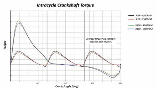
The benefits of the firing order do not end there. With a cylinder firing at every one-third turn of the crankshaft, the intracycle torque fluctuations are reduced considerably compared to many other engine designs, particularly the boxer twins that are popular across the UAV world.
“A boxer twin is essentially a big single-cylinder,” Hilbert observes. “Both cylinders fire at the same time, creating big accelerations and decelerations in rpm over the course of each cycle – in fact it produces negative torque between 180 and 360º of crank turn, which inputs a lot of resonance into the fuselage that you really don’t want, especially for surveillance, mapping or anything else needing HD video or photography.”
Vaglienti adds, “For as long as we’ve been in this industry, torque ripple has been the biggest source of the vibration
we’ve been fighting in IC enginepowered UAVs. Even when dyno-testing our relatively small A33, when it spins
at the resonant frequencies it makes the building shake. A boxer is far quieter, as its first- and second-order vibrations
balance pretty well, but when you install it on an aircraft, the torque ripple sends vibration all the way through to the
imager. In comparative terms, the I3 will be transformative for imaging quality.
“Overall, when you go from a boxer to an I3, because your power strokes are balanced so well by compression strokes, you reduce torque ripple by a factor of around five.”
While reducing torque ripple is perhaps the biggest benefit of the I3 design, it is not the only one. For instance, I3s trade out the yaw-oriented rocking couple inherent in boxer engines owing to the offset between its two crank pins (which can interfere with imaging stability) for a gentler, pitchoriented rocking couple that most gimbals can compensate for much more easily.
The I3 is also predisposed to better exhaust gas flow than boxers and singles. When the latter two designs fire, all the combustion gases are exhausted at the same time, and this pressure spike generates considerable noise. With the 1-2-3 firing order of the A99H, exhaust volumes are divided into three, and are evacuated smoothly from the exhaust manifold for much better noise filtering.
“Every bit of noise and vibration you take out of the engine means better ISR [intelligence, surveillance, and reconnaissance],” Hoag says. “You can fly lower without being detected to get closer images of the ground, and you can zoom in more stably without the camera shaking, for better pixel resolution.
“We ran mic tests on the A99 and our 100 cc twin. The A99 was always at least 6 dB quieter, even though the 100 cc has a special muffler we’ve designed specifically to make it quieter than other boxers.”
Drag reduction benefits can be gained from the long, thin aspect ratio of the I3, lending it well to aerodynamic cowls, and as a liquid-cooled engine the A99 requires no exposure to external airflow (with a radiator posing far less disruption to aero than finned cylinders) and can largely be packaged inside the hull.
One final benefit worth noting is the phenomenon of ‘cross-stuffing’. As the three cylinders share a common exhaust manifold, the pressure pulse triggered by one piston opening an exhaust port is exposed to the other two cylinders’ ports. In particular, that means the cylinder closest to compressing its charge can trap more of it.
“It’s the same phenomenon that ideally you get with a tuned exhaust system, where you have a wave that is reflected and comes back,” Vaglienti explains. “But instead of a long tube with your own pressure pulse reflecting and coming back, you’re getting the pulse from your neighbour 120º earlier in the cycle. Cross-stuffing boosts the power a bit and improves the engine’s fuel efficiency.”
Design & AM
The first design steps, in early 2018, focused on the cranktrain, with a goal of creating a robust and lightweight crankshaft. The crankcase was then topologically optimised around that, using some of the latest available CAD tools such as HyperWorks to identify and map each individual point of mechanical stress throughout the block, in order to effectively carve away all the metallic material that wasn’t stressed and therefore wasn’t helping to hold the engine together.
“We iterated that process three or four times to end up with an engine case designed for maximum stiffness with minimum weight,” Hilbert says. “And around that time we were also starting to dip our toes into metal AM, which enables us essentially to print a full bill of materials in a single build-plate.”
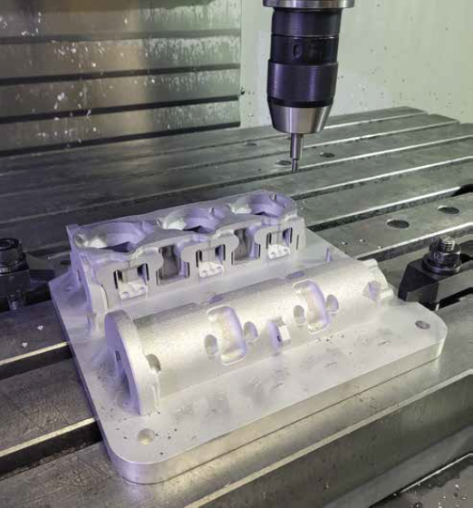
The build-plates printed by Cobra’s metal AM systems measure about 10 x 10 in, and feature both crankcase halves and all three cylinders. That enables them, and their cooling jackets and ancillary component inserts, to be extruded to very close tolerances before being moved to CNC machinery for cutting the metal engine parts from the plates.
The material is AlSi 10, with 0.1% manganese. Hilbert notes its similar mechanical and structural properties to A356 cast alloy, with some marginally reduced thermal conductivity compensated for by the liquid-cooling system.
“The average density of a casting is in the 80th percentile – there’s a lot of porosity in even very good block castings,”
he adds. “On the other hand, AM parts like these are 97-99% dense, with much lower part-to-part variability as well.”
Metal AM enables complex structures to be built but it is still time-consuming. Printing all the major crankcase parts on a single build-plate helps shrink lead times to 5 days per print, before being fastened together with titanium bolts.
Hilbert notes that the build-plate design incorporates some proprietary features to make the job of milling the cylinders and crankcase halves from the print easier, saving considerable time and tooling by not having to create special fixtures for first block-cutting operations.
“Before 2017, when the A33i hadn’t yet been released as a product, we’d spent ages tearing our hair out over cranktrain robustness and crankcase stiffness, and we were determined not to go through that again,” Vaglienti says. “This time we were determined to nail all that from day one.”
Much of the crankshaft design and simulation work experimented with different configurations, including whether to use four bearings or six. Notably the team eventually went with four, discovering that using six adds stiffness and strength but not durability. Using fewer bearings allows the crank to move more freely, and tolerate peak stresses better.
“It was a full year of CAE investigating metals, mechanical parts as well as fluid dynamics, not just for charge but also optimising the coolant jackets, along with several other areas,” Hilbert says.
“We’ve moved heavily towards Convergent for all our engine flow simulations. That’s a software tool that originated at the University of Wisconsin Engine Research Center, which handles moving boundaries and multi-phase really well. There are other toolsets out there, but we’ve seen Ford, GM and other big players switch to Convergent, so it seems to be the direction to be going in.”
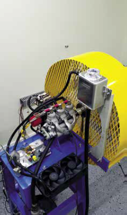
The first prototype print-outs for testing were produced in early 2019, and later that year some redesigns to optimise the cylinders and crankcase for AM were carried out. The first bench tests started in 2020, and more intensive dynamometer cycles had begun at the start of 2022.
The first two customers for the A99H are anticipated to take delivery of their engines later this year.
“We’ve worked to break the engines as much as we can,” Vaglienti says. “Tygerdyne’s dynos run our engines hard, but the data and engineering improvements that process yields are indispensable, and the power density and performance readings we’re getting are better than any 100 cc engine we’ve shipped before, and it’s quieter too.”
As a final note on the advantages of metal AM, Hilbert notes that a typical loop-scavenged two-stroke has a hole drilled down from the lower cylinder to the crank bearing, to force oil down into the latter using the pressure wave of the piston’s downstroke. Rather than straight drilling this hole, the A99H’s oiling holes can be printed, saving labour on drilling and in fact making the engine 12 mm shorter by printing curved holes (which are routed from the transfer port down to the bearing precisely where needed) rather than straight ones.
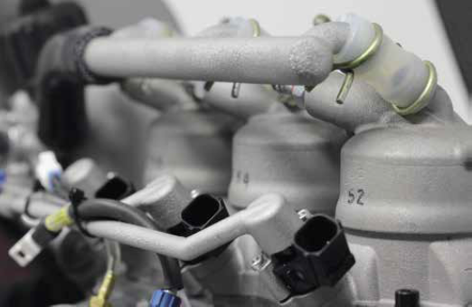
Charge
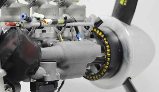
The throttle and plenum sit on the right of the engine, with a Futaba servo directly driving the barrel. “We’d spent unbelievable quantities of time dealing with the linkages in other engine designs; those took up maybe 20% of our r&d time so we got rid of them,” Vaglienti says.
The intake manifold is additively manufactured using PA12 Nylon (the same material as the A33’s cooling ducts) on an HP 5200 large-format printer. Standard loop-scavenging is used, with the pistons’ downward pressure forcing charge through the transfer ports, and the crankcase is separated into three chambers by the two main bearings and seals (otherwise, the I3’s crankcase pressure would always be the same).
As with the exhaust phenomenon alluded to above, the cross-stuffing effect ensures that each cylinder breathes independently. As one cylinder draws in air, the others are either compressing or shut entirely, ensuring dense air delivery where appropriate.
Regarding fuel, most boxer twins have a single injector that feeds into the crankcase, with the induction charge being blown into both cylinders simultaneously. Vaglienti notes, however, “The quality of charge transfer is a function of how each cylinder blows down on its previous cycle. So you can get an imbalance where one cylinder gets more charge than the other.
“In a gasoline engine, maybe that’s not so much of an issue: gasoline burns pretty well, even if your mixture isn’t perfectly on target for your maps. But a spark-ignited heavy fuel engine is much less tolerant of mixture error. Luckily, with an inline engine you’re obliged to fuel each cylinder independently, with an air seal between each cylinder.”
As such, the A99H has three injectors rather than throttle body injectors, which spray at 3 bar into the crankcase. Each cylinder scavenges and pumps on its own, as in a single-cylinder, giving the precise control over the charge mixture for all cylinders that’s needed for heavyfuel combustion.
This approach also helps performance in high transients. Heavy fuels are challenging to vaporise, which is why diesel engines often have extremely high pressure injectors to atomise droplets that are small enough to burn effectively. The conventional tactic of spraying fuel onto the reed valve would therefore not achieve sufficiently precise charge mixing for any significant changes in speed.
“One answer is to just cut back the performance of the UAV, but a better one is to move the injectors past the reed and downstream, directly into the crankcase,” Vaglienti says. “Then we worked hard on our IntelliJect software over several months to model how heavy fuel could be puddling on the crankcase surfaces, until basically we’d mapped what the sizes of puddles would be based on the operating conditions and how they’d change over transients.
“So now we can transition almost as well as a gasoline. At worst, moving the throttle from idle to 100% might take half a second, compared with twice as fast for a gasoline engine. Our software also allows us to do other clever things with the injection, such as deficit-track and skip-fire to account for puddling.”
Aiding this further is a glow plug mounted at the upper-rear of the A99H that serves as a pre-heater for the engine metal. As a high-current device, it can heat the heavy fuel rapidly, and the heated fuel sitting in the line above the cylinders can also warm the latter to help with a cold start.
Heavy-fuel handling
Hilbert notes that companies such as Orbital (see UST 11, December/January 2017) and Hirth (UST 34, October/November 2020) have switched to using air-assisted direct injection rails to handle their heavy fuel pre-ignition needs.
“I worked closely with Orbital’s system back in my Ford days, and it confers fantastic control advantages by moving the injector right to the head, as well as really fine atomisation; it’s a great solution,” he says. “That said such systems can be energy-intensive, problematic in packaging terms, and they’re also a little heavy and complex.
“And when you inject directly, you reduce the time in which the fuel can vaporise, so the actual quantity of useful air in the cylinder drops, unless you upsize the engine to compensate for the reduced power at the top end. Again, that means packaging and weight issues, albeit with the benefit of very efficient atomisation and timing control; the tradeoff we’ve gone with is targeting lighter, simpler and more aerodynamic.”
Naturally, when dealing with heavy fuels, an even bigger issue leaps to the forefront: knocking. As the probability of knocking increases with time and temperature, there are three typical approaches to preventing such preignition
(or outright explosion) events.
The first is to run at low loads, which many heavy-fuel engine designers achieve by expanding their displacements by 30-40% so that the load is lower relative to the engine and airframe volume. The second is to run the engine at higher rpm to give less time for knock to be initiated.
“Another way to solve knocking though is to have the combustion event happen quicker,” Hilbert says. “Chemically speaking, knock happens because of end-gases. As a flame front emanates from the spark plug, the gases in the cylinder that aren’t immediately burned become hotter and more pressurised as the flame front pushes them out towards the edges of the combustion chamber.
“With a smaller bore engine running at a high rpm, there’s less time for that to happen and less room in which it can happen, because there’s less distance for the flame front to travel. That’s another reason why we’ve gone with an I3 rather than, say, a twin for the displacement, power and fuel type we wanted for this engine.”
Further stability of the fuel-oil mixture has been achieved by consulting with VP Racing Fuels, who worked on heavy-fuel formulations, as well as choice of oil with Cobra and Power4Flight.
Crankshaft philosophy
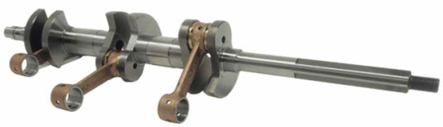
As mentioned, the crankshaft has received particular attention from the early stages of the A99’s design process. A key
goal has been to minimise the number of parts, as crank assembly and longevity can become more and more problematic as the number of cylinders goes up (in the absence of a monolithic shaft).
“You can do a twin-cylinder crank in maybe three or four parts, no major headache there, but when you’re trying to get a three-cylinder crank perfectly spaced with the pins 120º apart, trying to get all the bearings concentric with each other, the part count really goes up,” Hilbert observes.
“Starting at the front, you have the nose, then the front bearing journal followed by the first crank pin with its counterweights, then another bearing journal, then the middle crank pin, third bearing journal, back crank pin, rearmost bearing journal and shaft section.
“Originally, that all started as a seven-piece crank, but we already knew how tough that could be to assemble, align and afford. There are also potential durability issues from having so many parts pressed together. If a UAV suffers a hard landing or prop strike, that many crank parts could spin out of control.”
To reduce the crank part count, the front and rear crank noses are forged with integral crank pins, with the centre crank pin integral to one of the two mid-section ‘dumb-bells’, totalling four pieces pressed together after being forged from high-tension steel, then machined and superfinished.
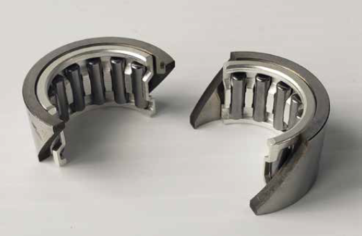
“It meant slightly higher tooling investments going in compared with using COTS pins, but it’s been great for reducing our part count, simplifying assembly and raising engine longevity,” Hilbert comments. “The only problem was the shaft journals for our main bearings – we couldn’t slide a typical off-the-shelf ball bearing onto the two centremost journals, because we forged the dumbbells as monolithic parts with the ‘pork chop’ counterweight on either end.”
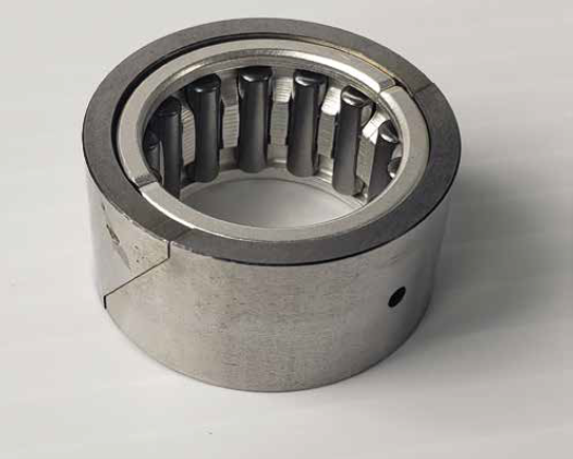
The team’s solution here was to use split needle roller bearings that could be pressed around the two middle journals, designing in-house the necessary external races and assembly technique after initially taking guidance from an existing high-speed, high-load roller bearing element. These are four-piece items (the inner element and outer race each splitting into two halves) with a 32 mm outer diameter and a hole in both the top and bottom race halves, the former for receiving oil and the latter having a stepping pin to fasten the race with the crank.
“The centre pins are large in diameter, and we wanted them that way, but they’re also extremely stiff as well as hollow and lightweight,” Hilbert notes. “The ball bearings on the ends and the needle bearings at the middle also have the same through-bore, so we line-bore the entire set of cases in one shot, with just one bore diameter.”
Vaglienti adds, “We can’t have the shaft hollows open during operation, because that would lead to ‘cross-talk’ between the cylinders, so machined plugs are pressed in there to prevent air moving between the crankcase sections and the cylinders.”
As in the A33, the con rods are single pieces, forged from steel before being shot-peened and copper-plated. Hilbert, Hoag and Vaglienti indicate that they have continued working flawlessly since we reported on them in the A33, so no changes have been made.
The pistons (still produced by Vertex) are cast from aluminium, with a few minor changes since 2017. Namely, their height has been reduced slightly, some friction reduction has been carried out, and they are now each fitted with a single piston ring with a semi-keystone cross-section, which helps it shed carbon deposits and prevent build-ups (a bigger problem in heavy-fuel engines than with gasoline, and one that directly shortens TBOs if not addressed).
“Using just one ring helps reduce friction too, and other aspects of that goal included improving the lip seals on the crankshaft, along with a lot of other little things,” Hilbert says.
Unlike the A33, the cylinders are printed as single pieces with their heads to make the design of the liquid cooling easier, reduce weight on the fasteners and eliminate points of failure (particularly regarding seals). Each bonds to the crankcase via four base bolts and a paper gasket; as in the A33, each one is coated with nickel silicon carbide and features two transfer ports largely similar in design to the A33.
“We’ve tightened our honing process to improve the coating of the closed cylinder dramatically, along with how we mask off the head,” Hilbert says. “We start with a rough bore and then coat a masking agent on the head before doing our final bore. We’ve also done a lot of CFD work to improve our loop-scavenging, and we’re about to start testing some new transfer ports that implement some of what we’ve learned there.”
Liquid Cooling
As discussed, the use of liquid cooling means system integrators can enclose the A99 inside their aircraft’s aerodynamic profile, improving their UAV’s drag efficiency by not having cylinders and dozens of cooling fins catching the airflow. That also helps reduce noise further by eliminating the ringing effect of many vibrating fins.
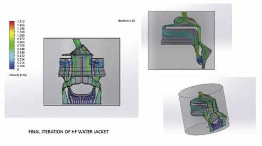
A waterless coolant from Evans is pumped through liquid jackets inside the cylinders. The team refers to these as its “precision-cooling jackets”, notably with separation of coolant flow between the head and walls.
“Liquid enters from below the exhaust port, and then there are three different passageways,” explains Hilbert. “The middle passageway directs coolant to the cylinder walls, and the two outer passageways lead up to the cylinder head.”
This approach achieves two goals. First, to maximise cooling efficiency for heavy-fuel handling, it can be useful to run a cylinder’s head hotter than its walls, as excess heat at the walls can degrade and even cause breaches of their oil film. Second, more heat at the head helps to vaporise the heavy fuel before the spark event.
More generally, the internal layer of liquid helps to muffle some of the combustion noise from the cylinders, and the improved heat dissipation from liquid cooling gives the engine overall higher durability and lifetime thanks to reduced thermal expansion and contraction, particularly at its seals.
“We’ve done FAR33 endurance testing, and found a direct causal relationship between how hot you run an engine and how long it lasts,” Vaglienti says. “Temperature affects carbon deposits, how well metal surfaces tolerate wear, and other things, and you see an exponential rise in the severity of these issues as you go up the operating temperature curve.
“Air-cooled engines will run for hours at 220 C, but not for 500 hours, and they can maintain 160 C for a few hundred hours but won’t give a 1000 hour TBO,” he adds. “We haven’t determined for certain what the maximum TBO of the A99H is, but it should go a long way – of the order of thousands of hours.”
While the A33 had an air plate that allowed cooling air through the cowling, the A99H has a servo-controlled mixer valve that can divert outgoing heated liquid to either the radiator to cool off, or back to the inlet area near the exhaust if a higher coolant throughput is more important than cold coolant – indeed, heavy fuel requires 40-60 C higher minimum coolant temperatures than gasoline engines. A custom thermostat is installed to monitor what action the mixer valve should take.
Exhaust manifold
While the A33 featured an active, variable bypass venting system in its exhaust, this has been temporarily shelved (pending ongoing r&d to optimise it) in favour of a simpler and less costly fixed exhaust for Cobra’s production engines.
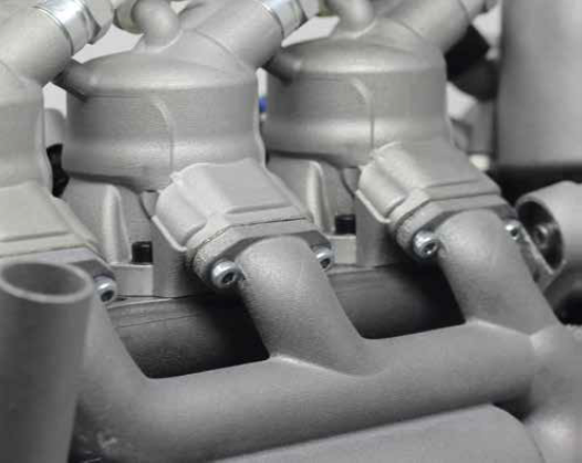
As indicated, the A99 instead uses an exhaust assembly that has a channel running from each cylinder linking into
a common manifold, with cross-stuffing meaning that one cylinder’s exhaust gas wave helps the containment and
compression of the next cylinder’s charge, akin to an exhaust valve.
“Also, the three blow-down processes aren’t fighting each other, they are cleanly separated so a thin, lightweight
packaging is sufficient,” Hilbert says.
Vaglienti adds, “We didn’t invent cross-stuffing, it’s from older racing days, but we knew from early results we could achieve it at low rpm. A lot of the iteration on the exhaust manifold has focused on maintaining the cross-stuffing at higher rpm.”
The manifold is produced using metal AM, enabling strikingly curved, complex, aerodynamic geometries to minimise drag and hence noise from the exhaust gases. The companies note that advances in metal AM are such that designing new iterations takes longer than printing them.
“Right now, they’re aluminium, but we may go to titanium in the future, which might be better for thermal stability,” Vaglienti continues. “We’ve left ourselves a lot of options in terms of materials and geometric tweaks, but we’re happy with our design methodology, and what we can achieve aerodynamically and acoustically versus traditional milling approaches.”
Engine and generator management
Engine management is achieved using Power4Flight’s IntelliJect ECU system, with a minor resistor redesign to increase the number of controllable injectors from two to three. This controls the throttle position, cooling pumps, mixer valve, fuel injection and spark timing. At a higher level of control, power commands are received from the end-user’s flight computer in terms of rpm and/or throttle levels, with the ECU then arbitrating how best to execute these, rather than performing them directly.
“Typically we want to limit the shear force with which the throttle moves, from a linear switch to a non-linear curve to deliver a curved power output,” Vaglienti says. “Aside from that, the engine is managed like any other: we have a crank position sensor for speed and timing readings, and we fire the three injectors and ignition systems to meet that.”

A global ignition advance table details the crank angles that the front spark plug should fire at relative to TDC, with the other two following at 120º intervals. Capacitive discharge ignition is used at present, as with the A33, although inductive discharge ignition might be adopted for both in the future.
Another table maps out how much fuel should be injected relative to throttle position and rpm. “We also have injector ratio tables, which divide up the total fuel to, say, 31% to be injected towards cylinder one, 34% to cylinder two and 35% to cylinder three,” Vaglienti continues.
“Because of the manifold geometry differences, you sometimes won’t have exactly the same richness or leanness between cylinders. The injector ratio tables account for that, and again they time it according to the crank angles.”
The ECU can also command the generator controller for engine starting in the conventional configuration, and it will command the generator system for series hybrid control in an upcoming version. In both versions, another device performs generator commutation; the A99H’s commutation will use Power4Flight’s IntelliGen system, while the series-hybrid A99’s generator controller has to be more powerful. In all likelihood, either the Velocity ESC from Currawong or the VESC from Trampa will be selected.
The generator can also be used to cold-start the engine (powering the glow plug as well as drawing on battery power to turn the crank) or maintain a given crank speed in the event of a fault or failure in order to execute a safe landing.
IntelliGen meanwhile will enable additional capabilities. For instance, during over-cooling, it could first have the generator take over the power outputfunction from the crank, then have it run the heater higher and open the throttle to undo the excess cooling and restore normal operation.
“We also anticipate IntelliGen having the intelligence to recharge VTOL batteries in flight, enabling more flexible manoeuvring and hovering while reducing the need for intermittent landings and battery swaps,”
Vaglienti says.
Hybrid future
The A99H’s developers are also working on a series-hybrid version called the A99S. This will be largely identical, save for a larger generator in place of the standard-issue alternator and prop, and capable of up to 4.5 kW continuous power output over a 70 V DC supply.
“The front end of the A99’s core design is modular and can accept various configurations of generator and propeller, be it direct drive or belt-driven,” Hilbert says. “For one of the first deliveries of the A99S we’ll have a 5 kW generator and intercooler on the exhaust.
“We’re also working on a gear head to mechanically translate higher shaft speeds into higher torque for running bigger, more efficient propellers, which we’ll be testing in a few months.”
Vaglienti adds, “Cobra is working on its own in-house generator engineering facilities, and its first motor/generators will be liquid-cooled. Thermal management is going to get really challenging for multi-kilowatt generators as the UAV market’s power demands go up and up, so getting an early r&d foothold there is vital.”
If the two companies’ r&d are any indication, further updates and enhancements to the A99 engine family will no doubt follow in the future, to match the growing needs of the UAV industry.
Specifications
A99H Spark-ignited two-stroke
Inline three-cylinder 99 cc
Case reed induction
Naturally aspirated
Heavy fuel and gasoline Liquid-cooled Fuel-oil mix: VP P4F heavy-fuel 50:1 pre-mix
Maximum shaft power: 7 kW at 8500 rpm
Peak generator power: 1.5 kW
Specific fuel consumption at cruise: 500 g/kWh
Weight: 3.65 kg
Some key suppliers
Throttle servos: Futaba
Pistons: Vertex
EFI: Power4Flight
ECUs: Power4Flight
Fuel pump: Currawong Engineering
Oil: VP Racing Fuels
Liquid coolant: Evans Waterless Engine Coolants
Engine scavenging simulations: Convergent
Performance modelling: Mod2T
Structural optimisation (FEM): Altair HyperWorks
Modal analysis: Altair HyperWorks
Dynos: Tygerdyne
Additive manufacturing systems (metal): Renishaw
Additive manufacturing systems (polymer): HP 5200 MJF
UPCOMING EVENTS


