


Avadi Engines
Rory Jackson investigates the benefits of a modern take on sleeve-valve engines, featuring a single rotating cylinder and a piston with two connecting rods
The era of UAVs has ushered in a variety of new approaches to power and propulsion as uncrewed aircraft manufacturers race to offer improved flight endurance, lower maintenance overheads, better fuel efficiencies, less vibration and other advantages over their competitors.
Some powertrain types, previously consigned to minimal, niche use cases, have experienced commercial uptake and success among UAVs, such as Wankel engines and proton exchange membrane fuel cells.
Some readers may eagerly rush to point out the perennial issues of these solutions, but the fact remains that they are today widely flown on both military and civilian platforms alike – for the various advantages they provide and for modern innovations that overcome key drawbacks or barriers to their use.
While technologies such as sleeve valves and rotating cylinder valves have also contributed to highly successful and mass-produced aircraft engines, their use faded out after World War II, partially due to being outpaced by advancements in turbine engines.
But with the tighter engineering tolerances now possible through modern design, material and manufacturing techniques, engines using rotary valves are making a comeback, as we have seen with RCV Engines (Issue 5) in Dorset, Britain and Strange Development (Issue 33; now Alpha-Otto Technologies) in Michigan, USA.
Further west in Washington state, Avadi Engines is a company that has gained attention for its lightweight, compact, low-vibration engine designs, particularly its MA-250 prototype, which used a sleeve valve for the highly reduced part count (and hence simplicity, weight and maintenance advantages) over conventional, poppet-valve four-strokes.
More recently, the company, led by CEO Landon Wilkinson, has thoroughly and definitively reworked the design of its flagship product, integrating the rotating liner technologies of its CTO, Dr. Dimitrios Dardalis, to overcome some key limitations of the sleeve valve and achieve its collective vision of an ideal engine for modern UAVs, with improvements in fuel economy and maintenance.
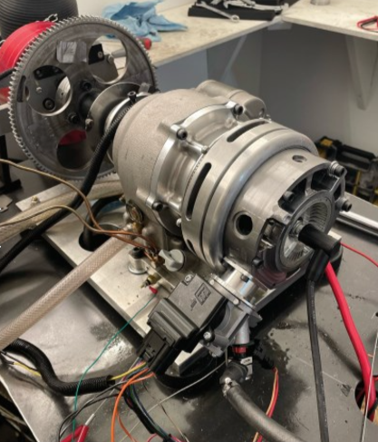
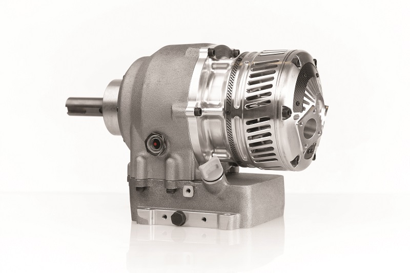
That vision is presented in the XMD-250 four-stroke, spark-ignited, naturally aspirated engine, which is anticipated to weigh 25 lb or less (14.1 kg), and produce 13 kW of indicated power and 31 Nm of torque at an operating speed of 4000 rpm. Wilkinson says power may increase by 15% or more after the intake and exhaust ports have been optimised via CFD.
As standard, the system has a horizontally disposed single cylinder and piston at the back, with the piston thrusting forwards into a crankcase, which features an oil pan beneath and an output shaft for directly driving a propeller in front.
From MA-250 to XMD-250
Avadi’s prototypes have consistently combined rotary valving systems with single-cylinder approaches in which a piston thrusts along the same forward, longitudinal axis that the engine’s output shaft and directly driven propeller rotate in. Hence, a slightly different mechanical approach (compared with that in conventional reciprocating engines) is needed for turning combustion power into shaft horsepower to account for the unconventional angle (or lack thereof) between piston stroke and shaft rotation.
The MA-250 design is operated using a self-centring, rotating piston, linked to a pair of counter-rotating, self-balancing connecting rods. Each one moves with a scissor-like motion and drives a respective shaft, with each shaft mounting a pinion gear. Both gears would run in a circular track fixed to the housing, hence driving the piston and con rods to rotate with the vertical stroke.
Mounted between the con rods on a pair of bearings (and hence directly driven by their rotational motion) was a ‘half-shaft’, serving as an output shaft for propellers, alternators or both. Additionally, a housing connected to the half-shaft and running upwards (or backwards) about the cylinder provided the valving for the system, opening and closing the cylinder’s intake and exhaust ports as it rotated.
This approach was claimed to minimise side pressure on the cylinder wall from the piston, and thus reduce friction, heat and wear compared with standard arrangements of the piston, con rod and crankshaft.
This is in addition to the traditional advantages of rotating valve systems, such as part minimisation and hence reduced points of failure or maintenance, compared with camshafts and their comparatively complex valve trains (consisting of lifters, pushrods, rockers, tappets, springs, valves and the like).
After several years of private development in Canada, the design was brought into Avadi Engines in Washington, where iterations on several aspects (primarily on the rotating valve configuration) resulted in the MA-250 prototype. Five were built and put through 30 hours of bench testing, including third-party trials, but ultimately, Avadi determined that issues of heat and a low flow coefficient merited a new approach.
Following Dardalis joining as CTO, by January 2023, the MA-250 was redesigned with his rotating cylinder valve approach, and without the half-shaft design, into what is known as the XMD-250 (Phoenix is also a working product name in the company).
Drive evolution
Dimitrios pointed out that Wilkinson and his team had designed unnecessary complexity into the MA-250 to achieve the piston, half-shaft and cylinder rotating in unison.
Despite their assumptions that benefits would be gained by spinning the piston and cylinder together (particularly by preventing wear on the piston rings, which typically occurs near TDC as the dropping speeds reduce the protective effects of the oil film about the rings), he had many years of test data and experience indicating that there was no harm in the piston and cylinder rotating at different speeds, or one not rotating at all.
“The original designer of the MA-250 didn’t know the extensive history of successful sleeve valve engine designs. In fact, most people don’t know the benefits of having a relative rotation between the piston and cylinder wall in a sleeve valve engine, although I’ve accounted for my test results of trialling them in several SAE papers,” Dimitrios says.
“Landon originally asked me just to integrate my rotating liner technology into his engine, but I eventually asked for a clean sheet to make the whole power plant mechanically simpler.”
How it works
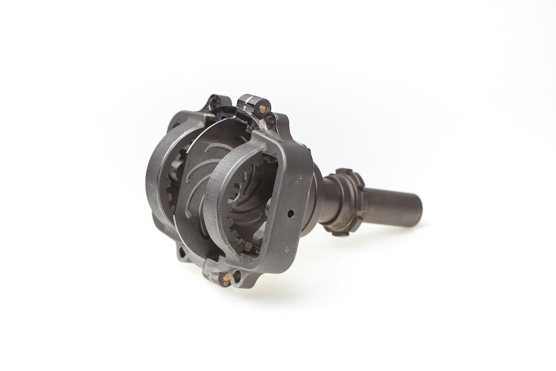
In the XMD-250, as the piston thrusts away from the cylinder head post-combustion, it still drives two con rods moving in a scissor-like motion, each one connected by conventional roller element bearings to a respective shaft, with each shaft affixed to the engine by three differently sized roller bearings.
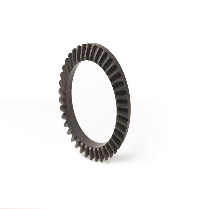
Each shaft drives a pinion gear with 20 teeth. As these gears counter-rotate, their teeth mesh with other teeth on the underside of the cylinder above, and on the top of an output shaft below (these latter two are ring gears with 40 teeth each; all four being cut as bevel helical gears). The cylinder runs in a large, single, deep-groove ball bearing for handling thrust and side loads, while the shaft runs in two smaller bearings.
“Gears typically have 95-97% efficiency at high load when properly optimised, so a 3-5% loss is expected. However, any gear reduction to drive a propeller will have some efficiency loss,” says Wilkinson.
The cylinder and shaft counter-rotate relative to each other, and as the shafts, con rods and piston maintain a fixed, non-rotational axis, the cylinder rotates about the piston.
The cylinder’s rotation, compared with the non-rotating piston, helps keep the piston rings ‘hydroplaning’ over the oil film separating them from the cylinder walls, including near TDC, where (as Dardalis’ research indicates) friction between the cylinder and piston ring tends to be highest due to the much slower piston speed there – compared with mid-stroke and BDC speeds – dropping the surface tension of the oil film and allowing the ring metal through. Instead, the constant rotating motion helps maintain the oil-pressure level necessary for forcing the piston ring and cylinder apart.
Inside the rotating head atop the cylinder is a port (referred to here as a transfer port). As it rotates, it moves the transfer port opening over a stationary intake inlet and exhaust outlet located in a cylindrical ‘stator’ housing encircling the head. This exposes, and then closes, the inlet and outlet to the combustion chamber; thus the head is the rotary valve mechanism in the XMD-250. The MA-250’s axially positioned valves created heat-transfer issues that their new position in the XMD-250 has eliminated.

“Just as in sleeve valve engines, the rotation of the cylinder head – and also the roller bearing near the bottom of the cylinder – reduces the impact on it of very high thrust loads from combustion,” Dardalis says.
“And keeping the head and cylinder integral, and rotating together, means we avoid the issue of sealing and oiling between them – we bond the two parts together with a conventional static seal between them.
“But, importantly, there’s nothing special about the crankshaft-gear system, other than that there’s two counter-rotating cranks. A 2:1 gear reduction inbuilt to the design enables direct drive of propellers, as the 3500-4000 rpm of the engine drops to 1750-2000 rpm for a prop.”
In addition to Dardalis’ extensive use of CFD via Converge and Matlab to optimise the XMD-250 design, Avadi has invested heavily in its in-house CNC machining capabilities for rapid prototyping and control over adjustments where necessary.
“New valve systems tend to be difficult to get right in new engines, so if we succeed with the valve design, we anticipate the remaining optimisations shouldn’t be overly difficult or complex,” Wilkinson says.
Rotary ups and downs
General advantages of well-optimised rotary valve designs over poppet valves are well-established in literature, and Dardalis points to several examples. For one, the rate at which they open and close can be higher than that achievable with poppets, improving volumetric efficiencies at high rpms while retaining good torque at lower speeds.
Fuel and air get more direct intake flow paths without needing to travel around the intake valve seat, increasing flow coefficients and volumetric efficiencies at high speed. The absence of a hot exhaust valve above the piston increases the engine’s tolerance of possible detonations, and allows for tighter compression and a higher compression ratio.
“The XMD-250 has similar operating principles to RCV Engines’ original designs. They also once used a rotating cylinder, with ports in the cylinder side walls, and all the advantages that we’ve discussed from that approach above. Only relatively recently did they move the valving to the cylinder heads,” Dardalis notes.
“Regarding TBOs, the cylinder rotation should minimise ring and bore wear, and once the rotary valve is refined it too may have very low wear. Furthermore, if the intake air is kept clean or well filtered, and the oil frequently changed, we may have a TBO multiple times the standard in UAV engines.”
The disadvantages of rotary valves relate largely to sealing and oil-control challenges. A closer look at the XMD-250 reveals how Avadi resolves such issues.
Sealing
The transfer port inside the cylinder head runs upwards from approximately TDC, offset by roughly 45° relative to the angle of the stroke, to form a side opening that passes over the stator’s air inlet and exhaust outlet as the head rotates.
“The transfer port’s opening is circular, and the inlet and outlet have convex edges matching the opening’s curvature, enabling rapid opening and closing of the flow area for maximum volumetric efficiency,” Dardalis explains.
“However, the key question is around how we seal that tiny, thin gap between the head and the stator, preventing blow-by into the rest of the engine, because in both intake and exhaust, high-pressure gas passes through that port, and it’s going to slip into every crack and gap it can find.”
One aspect of the current method is a ring seal around the opening of the transfer port, which is pushed by spring force to plug the interface between port and inlet/outlet, but Avadi is adopting another system now as the primary seal (the ring seal being a backup measure), which may be harder to machine and tune, but brings better oil control.
“It’s an idea called a sleeve seal, which didn’t exist in the World War II heyday of sleeve valve engines, nor did their designs need one. We first saw something similar in a motorcycle engine from England in the late 80s,” Dardalis explains.
“It’s a spring-loaded sleeve, encircling the cylinder head, with a machined opening matching and fitting over the transfer port. Like a piston ring, it wants to open outwards, and that expansive tendency enables it to plug the gap between cylinder head and stator.”
Above and below the sleeve seal’s inlet/outlet port are two oiler holes (four in total), which pass over oil-injector chambers elsewhere in the stator, with their positioning ensuring a preferential buildup of oil film specifically above and below the port. The positions of the oiler holes prevent oil from entering the transfer port, and air from passing upwards or downwards into the rest of the engine.
“If a minutely thin channel or bubble of fuel air escapes into the narrow band between the upper and lower oil films, that’s fine – it doesn’t interfere with lubrication or lead to blow-by,” Dardalis affirms. “We’re also researching spiral grooves or other surface features for improving the oil control about the sleeve seal, and helping the oil to handle loads and prevent metal-on-metal contact.”
As a final measure, two oil-control piston rings – one atop the outside of the cylinder head and one at the bottom – block axial blow-by flow at the top and bottom of the valve.
Oiling
Two main oil injectors atop the mid-section directly lubricate the pinion gears and shafts, with splash lubrication covering the five SKF roller element bearings (plus the two needle bearings in the con-rod big ends). The output shaft’s two bearings are less exposed to the splashing; to compensate, a small, additional oil flow is delivered via an injector near the propeller governor.
An oil pan connects to the bottom of the crankcase via a small, central aperture, where oil can enter via gravity. The pan has a slightly conical shape to encourage recovered oil to pass into a lower outlet for recirculation. Cooling fins are cut into the pan’s underside to help remove heat.
The oil pump is a mechanical system standard in small engines, chain-driven off the output shaft, as Dardalis favours this simplicity and reliability over the vulnerability of an electric pump.

He says: “Like in other small aircraft engines today, all our bearings are either deep-groove or angular-contact roller element devices, which lets us use a relatively low-capacity oil pump to keep them lubricated and cooled.”
The rotating cylinder head has critical lubrication requirements of its own, with strict oil-regulation limits that past sleeve valve engines could not overcome.
“Meeting those requirements comes down to controlling oil pressure, which is very difficult. Oil pressure changes depending on engine rpm, oil temperature, the state of wear in the engine’s bearings, the grade of oil you’re using, and other factors,” Dardalis says.
“In our approach, we’ve built a super-simple, positive displacement pump, which delivers a very small and fixed amount of oil per cylinder rotation very consistently. It sits in the stator and contacts the sleeve seal via a small plunger. An eccentric lobe on the sleeve drives that plunger in and out by around 0.25 mm on average, with one reciprocation per valve rotation [corresponding to two crank rotations].”
Behind the plunger are channels with two check valves: one connected to the oil pump that allows oil to come in, and one that lets the oil come out. The former is regulated such that the amount of oil that comes in is physically triggered by the backwards motion of the plunger, which mechanically opens its check valve, so there is a fixed limit on how much oil can enter.
“The design of this valve system is intended to help us achieve a longer TBO than most small engines, because in theory it completely prevents metal-on-metal contact between the sleeve and stator wall,” Wilkinson notes.
Dardalis continues: “It is like the injection you’d see in an old diesel, which spits a small amount of diesel for each rotation. It’s just been reconfigured to spit incoming oil out of the system whenever oil pressure inside is high enough to overcome the extractor check valve.
“We don’t need the super-high fuel atomisation of the old diesel-injection pumps, just oil flow in very small amounts, and then an insert in the sleeve seal along with the oiler holes diverts the oil coming in past the plunger to specifically run in the circumferences above and below the transfer port opening, instead of just coating and overrunning everything indiscriminately.”
As a final measure against excessive oil around the sleeve seal and head, an oil-recovery channel in the stator lets oil escape to the pan for recirculation. The channel is thin due to the oil film being micron-thick (so total oil is minimal).
While some sleeve valve engines used oil for cooling as well as sealing and lubrication, thermal loads on the XMD-250’s sleeve seal are minor. The cylinder head takes most of the combustion heat, and an air-cooling approach (explained below) dissipates that.
“Going forwards, either the sleeve or stator will have a hard chrome treatment,” Wilkinson notes. “And while the stator is currently steel, there’s no reason we couldn’t make it from aluminium to save around 2 lb [900 g] of weight, with nickel silicon carbide on the inner wall for hardness. We might then go with another steel for the sleeve seal, or even remove it if the nickel silicon carbide’s hydrodynamics provide for our oil control and sealing needs.”
Starting up
The rest of the engine’s operations and ancillaries are largely conventional. Depending on the application, the engine can start via “a typical motorcycle sprag clutch or flywheel with an electric motor [or] alternatively we have a relationship with ePropelled, who can supply a hybrid starter-generator and electric-motor configuration, which starts the engine with the motor and then converts to a generator once the engine is running”, Wilkinson says.
The hybrid starter-generator of choice in the latter is ePropelled’s SG12000, a 4.3 kg system delivering up to 150 A or 14 kW, although further integrations of starter generators in series are being designed, which would achieve a combined power output exceeding 16 kW.
Intake and management
The XMD-250 is naturally aspirated with throttle-body injection, the fuel and air mixing conventionally as they travel down a tuned intake manifold about 9-12 in (22.8-30.5 cm) long, guiding them to the stator inlet and transfer port. Injection quantities and timing, along with the throttle servo angle, are mapped and governed using an off-the-shelf Walbro EFI/ECU combination unit.
“Dynamometer testing uses a straight intake pipe on the engine. However, we’d naturally design something different for a field-use or flight-testing model for better integration, tuning and mixing,” Wilkinson says.
“The engine-fuelling configuration can be customised to the design of the UAV platform. Typically, there’s a gravity flow of fuel to the EFI fuel pump, which then supplies fuel to the injector pump. The whole system runs on a 12 V power source.
“And while the Walbro unit has been great for testing purposes, for UAV applications there are ECU and EFI solutions that Northwest UAV (NWUAV) can implement on our behalf – they’ve been of invaluable help in their advice and support throughout our r&d.”
Avadi’s longer-term plan is to stay agnostic to ECUs and EFI controllers (porting the control software and mapping from one system to the next) to enable the adoption of new, more optimised ECUs or those preferred by a UAV developer.
Combustion matters
The combustion chamber has an unconventional shape due to the angled, tubular transfer port.
“Normally, you want your spark plug right at the centre of the combustion chamber, so the flame can propagate out to all the edges of the combustion chamber as smoothly as possible, but because the transfer port inescapably forms part of our combustion chamber, we get a very asymmetric chamber geometry,” Dardalis says.
“What we’ve found, however, is that as the piston closes on TDC, that squishing effect forces the gas to rapidly compress inside the transfer port – as it has nowhere else to go – and that creates high turbulence inside the port.”
The spark plug is positioned centrally in the cylinder head. This substantially offsets it from the centre of the transfer port, but it cannot be offset from the centre of the cylinder head to position it more symmetrically (relative to the transfer port’s shape) due to how the cylinder head rotates, and the wiring and integration problems this would cause.
Avadi, however, sees potential for CFD optimisation of the transfer port geometry for improved squish, tumble and combustion quality.
“We might, for instance, add more volume in the head towards the rear of the port and still be able to hit our high compression ratio. The port design is only in its first draft now, so we anticipate many more versions of it, and the
XMD-250 to follow,” Dardalis says. Wilkinson adds: “The piston, of course, could also play a part in that optimisation: a plug or other convex shape atop the crown could, for instance, protrude into the transfer port at TDC for higher compression. We had such a design feature in the MA-250’s piston; we just haven’t tried it in the XMD-250 yet.”
Aside from all of this, the combustion and power stroke are conventional, with no direct efficiency relationship between the thermodynamics of the engine and its mechanical design.
“Essentially, the combustion doesn’t know that an unusual crank system exists, but it could integrate efficiency improvements over time; for instance, the double connecting rod could one day use a very low connecting rod-to-stroke ratio, assisting with turbulence at high or low speeds,” Dardalis says.
The intake and exhaust ports are offset at roughly 250° (crank angle degrees) from each other, with about 110° between the exhaust and intake, as the width of the ports (about 1 in, or 2.54 cm) means gases start flowing through long before the transfer port perfectly lines up with the inlet or outlet.
Again, however, Wilkinson and Dardalis emphasise that this first design of the stator and transfer port was based on calculated assumptions of flow coefficients, with real-world CFD testing of the XMD-250 prototypes and benchmarking of the actual flow coefficients to inevitably refine the next versions’ geometries.
“We don’t want to wait for the CFD to be over before we build prototypes. We want to develop as many of the concepts as we can, so the next version can have power efficiency and generation improvements across the board,” Dardalis adds.
On power generation, Wilkinson notes that the flywheels (which primarily serve to smooth power and vibration from the piston, as conventional) present a strong opportunity not only for efficiency optimisations but also for capturing the engine’s power output as electricity by replacing the current steel flywheels with permanent magnet rotors running in copper-wire stators.
He comments again that ePropelled’s motor-generators hold great interest for his team in how well they would integrate and run at the ends of the gear cranks.
As a final point, Dardalis adds that past its rotary valving, the exhaust system is entirely conventional and will run with any choice of pipes or mufflers.
Cooling down
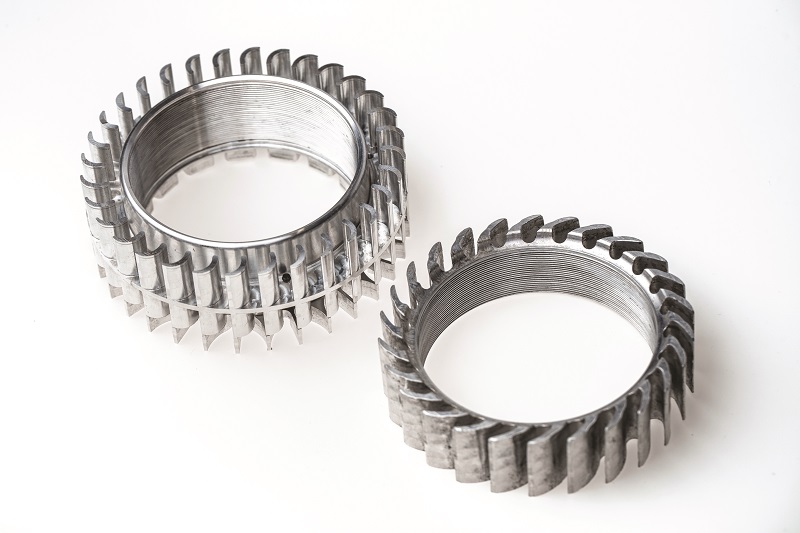
A forced air-cooling effect on the combustion chamber is created using the rotating cylinder. Two concentric sets of fins are installed near the top of the engine: one on the cylinder and one below the stator.
As the cylinder and its fins rotate, their motion relative to the stationary stator fins acts as a blower, centrifugally pushing air outwards, radially from the stator fins. A series of ports running axially, up through the stator and directly above the fins, serve as inlets for air to be drawn in as the air pressure inside the stator fins drops.
“The cylinder head is a different story,” Dardalis notes. “We currently have fins in the top of the cylinder head, which run shallow above the transfer port and deeper around it, and those inherently dissipate heat.
“But, with some CFD and tuning for efficiency in subsequent iterations, it will also create a forced-air effect as the head rotates, likely via some ports we will cut into the side to serve as cooling air inlets and outlets once we’ve identified spots where leakage of oil from the transfer port to the outside won’t be an issue.”
Looking ahead
With the first few prototypes of the XMD-250 now complete, Avadi has several industry partners awaiting the results of its first testing runs (currently under way) such that trials in their UAS platforms can be discussed and arranged for applications ranging from military operations to commercial logistics.
Avadi anticipates that it will pursue another funding round through Startengine.com before the end of this year, which is aimed at gathering sufficient runway to accelerate its optimisations. The company will then scale up production of its engine to meet its backlog of initial waiting list orders the following year.
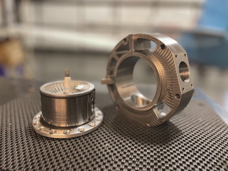
Anatomy
The main engine housing is presently CNC-milled from aluminium 6160 in three parts: two main crankcase halves split lengthways (parallel with the piston stroke and output shaft), and a ‘jug’ that mounts and supports the stator. Once the engine is productionised, Avadi will probably cast the housing parts for more cost-effective, durable manufacturing.
The rotating cylinder is CNC lathe-cut from steel and heat-treated, with a hard chrome plating inside (hardened steel has been used in past iterations and, as discussed, nickel silicon carbide is being studied as a future solution).
The sleeve seal is cut from polished 1045 steel, while the cylinder head is CNC-milled from 7075 aluminium, with a precision finishing procedure on the outer diameter’s surface to ensure a tight fit and good hydrodynamics with the sleeve. Due to the cooling fins’ thinness, the head may be additively printed in future, but as their shape is not complex, the company will first study casting (with finishing processes afterwards) for feasibility, possibly using aluminium 7071, before going to additive printers. The two-piece stator meanwhile is cut from 4140 steel.
The piston is CNC-machined aluminium for weight, while the connecting rods are machined as single pieces from hardened steel. The three rings about the piston are described as very standard components (both chromoly steel and stainless steel rings have been used), but Avadi plans on adding pins to fix them in place (as sometimes seen in two-strokes) to limit their floating and interference with oil hydrodynamics. The oil-control rings around the top and bottom of the cylinder head are iron.
Down in the crankcase, the pinion gears, ring gears (at the top of the output shaft and the underside of the rotating cylinder), and shafts are all cut from heat-treated and hardened steel. Both pinion-geared shafts and the output shaft are cut as single pieces.
The oil pan is currently cut from aluminium in two parts (split lengthways as the crankcase is), although it may be cast or printed from a high-temperature polymer in later versions.
Specifications
- XMD-250
- Some key suppliers
- Spark-ignited
- Single-cylinder
- Naturally aspirated
- Rotating cylinder valving
- Air-cooled
- Hard chrome liner
- Weight: 14.1 kg
- Bore: 7.8 cm
- Stroke: 5.2 cm
- Maximum continuous power output: 13 kW
- Maximum continuous torque: 31 Nm
- Maximum continuous speed: 4000 rpm
Some key suppliers
- CNC machines: Haas
- Dynamometers: DYNOmite
- CAD software: Autodesk
- CAD software: Dassault
- CFD software: Convergent Science
- Various engine components: McMaster Carr
- Engine development support: NWUAV
- Pinion gears: Batom (AKA Great Taiwan Gear)
- Bearings: SKF
- Oil valves: Swagelok
- Starter-generator: ePropelled
- ECU & EFI: Wahlbro
- ECU & EFI: NWUAV

UPCOMING EVENTS


