


Antennas

Today, the mission-critical antenna is front of mind when building an uncrewed vehicle, Rory Jackson reports
Aerial manoeuvres
Since before this publication started printing there has been a strong tendency throughout the uncrewed systems world for vehicle designers and manufacturers to model, prototype and optimise their new-generation vehicles from concept to showcase demonstrations without considering antenna type or integration very closely, if at all.
Despite manufacturers globally willing for this to change, uncrewed system manufacturers can still underestimate how sensitive antenna performance is to hull configurations and materials, vehicle dynamics, onboard power, and countless parameters of the mission and environment to be tackled by the vehicle in operation (including the mounting risk of jamming, spoofing or even simple congestion of data links whether within or far from a warzone).
Given all the little details that can play havoc with an uncrewed vehicle’s mission-critical data links – including its C2 connection, its GNSS fix or live camera feed – it should come as little surprise that uncrewed systems engineers consistently increase their comms and mission success rate, and shorten their product’s time to market when specifying that the antenna is front of mind in vehicle design, for there is much to specify in every antenna.
Regardless of whether one is integrating a monopole, dipole, helical, patch or sector antenna, most antennas in the uncrewed vehicle space tend to consist of a few core parts.
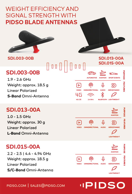
Starting at the top or outermost parts of the antenna, one arguably finds the most important part: the active or driven element. This connects with a radio or GNSS receiver and interacts with electromagnetic fields to receive or transmit RF signals. It typically presents as a metal rod as per a monopole antenna (in ‘whip antenna’ form; monopoles housed in a blade-like aerodynamic fairing are referred to as blade antennas) or two symmetrical rods per one dipole antenna, a flat square of metal in a patch antenna, or as many elements combined in an array antenna. As the active element directly regulates the antenna’s resonant frequency and radiation pattern, optimising it is fundamental.
Beyond the element is an internal network of devices typically comprising capacitors, inductors and transformers designed to optimise the impedance matching with the coaxial cable that links the antenna with the radio, thereby achieving the highest possible rate of power transfer and the lowest possible rate of radio signals being reflected back from the antenna (which leads to losses and distortions).

Following this, bandpass or band-reject filters are application-critical circuits that allow signals of certain frequencies to pass through the antenna and block others from undesired radio frequency (RF) bands, so choosing the right filters is paramount for safeguarding signal integrity against congestion, interference, and so on.
Internal matching networks and filters tend to be most complex in ultra-wideband (UWB) antennas; GNSS and satellite communication antennas will often also integrate a low-noise amplifier (LNA) somewhere between the internal matching network and receiver to boost the very low-power signals coming from satellites without excessively decreasing signal-to-noise. Like filters, LNAs must be tuned to accept and amplify signals, particularly frequency bands, and, by comparison, drown out-of-band signals.
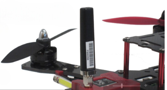
As one nears the radio or GNSS receiver, one may find a spring base for allowing the antenna to bend and sway flexibly without breaking, maintaining its integrity and functionality in hazardous environments prone to physical contact, such as forests, warehouses or cramped urban corridors.
If using a monopole antenna, one will find a counterpoise for reflecting the active element’s electromagnetic (EM) waves into an efficient radiating system with the ideal radiation pattern and impedance characteristics (naturally, size and positioning closely relate to antenna performance).
At the base, one finds a connector – usually a SMA, N-Type or BNC, chosen for the frequency range and power levels of the application – and a coaxial cable, which together link the antenna to the radio or receiver. Signal integrity and connection efficiency depend on the quality of the connector and cable.
While these might not seem like an especially long list of building blocks, they encompass a massive algorithm of instructions that antenna manufacturers require of uncrewed systems engineers at an early stage to do their job optimally.

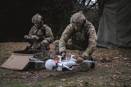
uncrewed vehicles squeeze through cluttered areas (Image courtesy of Southwest Antennas)
Conversations with antenna makers
A detailed description of the intended mission of an uncrewed vehicle will define the range, data rates, GNSS accuracy, and likelihood of obstacles or interference sources, which the antenna must be designed around (and extensive discussion of these points between customers and suppliers should account for how these may change between stages of an operation).
A new UAV’s design bears numerous factors of high concern to antenna manufacturers who want to achieve the ideal construction, placement and specifications for the antenna they end up supplying, in order to maximise project success, and minimise failures and complaints down the line.
For instance, the presence, type and geometry of carbon fibre used in the hull can act as a ground plane, altering the antenna’s radiation pattern, or it can block RF signals outright, meriting the use of RF-transparent materials over select parts of the body. Similarly, RF-isolating the antenna will become more important as the potential for self-jamming from other onboard electric or electronic subsystems rises.
Additionally, the integrator’s request for a certain range and strength of data links for a mission’s duration may exceed what the available onboard power can provide due to insufficient battery or fuel capacity, or sharing power with other onboard systems (which may include power-hungry payloads such as Lidar, 4K cameras or mid-wave infrared (MWIR)).
A UAV with a large, hybrid powertrain could be well placed for powering strong and consistent links for control, video and satellite navigation. However, if that powertrain is there for the aircraft to undertake high speeds and dynamic manoeuvres, and the antenna maker is not informed of this, then the antenna might not be designed correctly to maintain signal continuity and strength.
Designing and optimising the perfect antenna for myriad mission requirements and vehicle specifics entails covering a great many antenna-specific parameters beyond perennial constraints such as SWaP-C, packaging and IP rating. Its bandwidth will change based on operational requirements: a narrow-band antenna works for minimal data transmission over longer distances, such as in remote monitoring and control of commercial applications.
For moderately higher data rates, a wide-band antenna may be necessary, but for very high rates, such as real-time video, Lidar or sonar streaming, the antenna’s frequency range will be dictated by a combination of regulatory, environmental and operational needs.
Close understanding of the mission profile will help in choosing or tuning the antenna’s azimuth and elevation beamwidths. These define the angular range over which it radiates or receives energy efficiently, and hence the coverage area and directivity of its data links. Collectively, these qualities are vital to maximise an antenna’s gain, or how well it converts input power into radio waves in a specific direction during transmission, and radio waves received from a particular direction into electrical signals during reception.
All these qualities will be influenced by the maximum RF power that the antenna can handle, which can be governed by regulations but will also affect communications consistency at range.
Polarisation
Polarisation, the direction of EM fields produced by the antenna, and hence the direction in which energy moves away or is received by it, is a factor of antenna success that is widely discussed in our previous features. Each of the established forms of polarisation finds its use among uncrewed vehicles. Circularly polarised antennas, for example, where the RF wave rotates as the signal propagates, can be applied in operations with air-to-ground links where orientation between a UAV and its ground control station (GCS) can vary.
Linear polarisations, whether vertical or horizontal, are commonly seen in omnidirectional antennas used for LOS communications. Some modern multiple input, multiple output (MIMO) configurations now integrate more than one omnidirectional antenna to achieve both vertical and horizontal polarisation simultaneously, covering off the nulls in the doughnut-shaped radiation pattern.

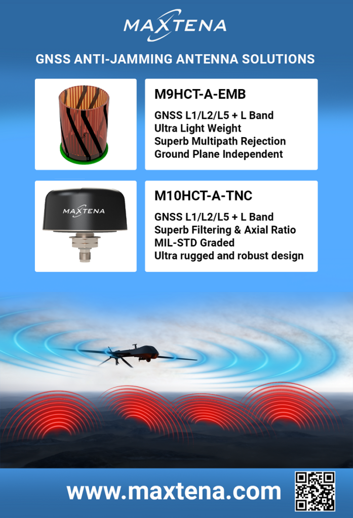
In addition, there has been increased interest recently in multipolarised antennas, which can passively achieve multiple combined polarisations in a single-input antenna element, thereby enabling consistent data links in dynamic environments and networks without having to resort to the complexity, size and power of active beamforming MIMO arrays, or the limitations of a singularly polarised antenna.
As of writing, one of the most successful, multipolarised antenna designs uses a 3D copper element (as opposed to 2D patch antennas or 1D monopoles) that is handmade precisely to capture multiple frequencies.
Optimisation of such systems makes judicious use of spectrum analysers and vector network analysers (VNAs) for cycling the handcrafted elements to observe in real-time the frequencies they are being attuned for. Doing so produces metrics that directly inform how the lengths, geometries and orientations must be tuned across its 3D structure to achieve the customer’s desired polarisation, frequency, bandwidth and so on.
Despite being handmade, such antennas can be manufactured in volumes of tens of thousands per year, with lead times of less than a few weeks for batches of a few dozen or hundred. Hence, granular details on their production methods are proprietary, and many of the designs are patented, with different ones being optimal for UAVs, UGVs, USVs, stationary GCSs, body-mounted GCSs and so on.
The evolving antenna
Technological advancements in other areas are helping to optimise antennas to meet the pressing requirements of today’s uncrewed systems.
As vehicles integrate higher numbers of data links, the development of antennas with internal bandpass and band-reject filters greatly enhances signal selectivity and minimises interference from co-located radios working at different bands, thus improving comms clarity and integrity for each link. Increasingly popular forms of internally filtered antennas include filtering microstrip antennas, filtering dipole antennas and (for 5G networks in particular) millimetre-wave filtering antennas.
Also becoming more popular and widely offered for GNSS use are helical antennas. These have not been historically preferred by geospatial surveyors due to the instability of their phase centres – the apparent point from which EM radiation seems to spherically emanate – which limits their repeatable accuracy to a centimetre rather than millimetre level.
However, for uncrewed systems, centimetric accuracy is often more than sufficient, and helical antennas are among the most weight-efficient configurations available, competing with monopoles and patches, but unlike the latter two, helical antennas do not require a ground plane to work, making them easier to integrate and operate.
Additionally, as UGVs increasingly work in crowded streets and buildings, and as USVs become permanent fixtures of harbours, oil rigs and wind farms, the chance of accidental collision rises dramatically (while an uncrewed vehicle’s obstacle avoidance may work perfectly, human feet, moving doors and strong waves may not oblige).

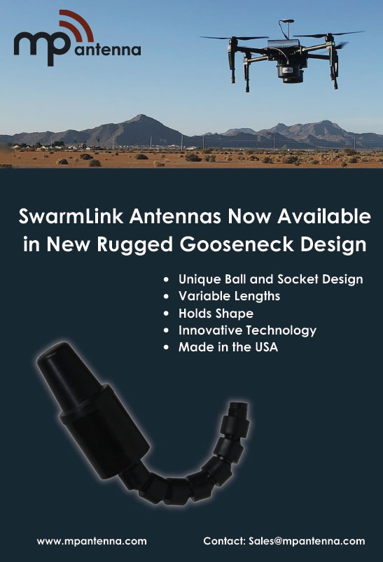
As well as high vibrations and impact risks, USVs working amid strong sea states or UGVs on uneven terrain can suffer intermittent comms losses (depending on the power, polarisation or other factors of their antenna), but the development of articulated adjustment capabilities now enables antenna angles to be adjusted by up to ±90° to optimise signal reception and transmission by adjusting the antenna’s angle.
Fortunately, significant improvements in the mechanical robustness of new antenna products through selecting, adapting and validating enclosure materials and geometries from other ruggedised componentry have been achieved, reducing the rate at which they are damaged in operation or need replacing. Such improvements are also now accounting for chemical corrosion risks, which are pronounced risks for UAVs and UGVs performing agricultural spraying.
Lastly, while one might assume antennas for GCSs are a solved technology, with stationary broadcast and reception for fixed ground systems having existed for over a century, new forms of tracking antenna are coming out with the ability to more precisely maintain directional links with UAVs.
Innovations include installing specialised tracking modules on UAVs that feed real-time position and attitude data back to the tracking antenna assembly, regardless of autopilot and GCS selections, and also the integration of new electric motors and ESCs that enable the antennas to pan and tilt with fast reaction times, maintaining coverage even in highly dynamic operations. Smart search patterns and similar behaviours embedded into tracking antenna software can also enable the recovery of lost links, thereby preventing the loss of a mission or vehicle.
(Image courtesy of Southwest Antennas)
The design process
Following copious discussions on platform anatomy, mission specifics, environmental considerations, frequency requirements and so on, a Request for Information or similar document can be formed, summarising the customer’s needs and specifications in a way that informs a new antenna’s initial design concept, whether it be a blank sheet design or the modification of an existing antenna.
From our research, we surmise that at least a small majority of new antennas in this industry are customisations of existing designs to reduce SWaP-C parameters and be better suited to uncrewed vehicle requirements, as some manufacturers are now doing with designs unveiled not so long ago.
Further technical dialogue, along with judicious simulation of the antenna’s electromagnetic, electrical and mechanical properties in industry-standard software such as CST can formalise these high-level requirements into an effective blueprint for antenna engineers to prototype something with adherence to exact technical specifications, performance criteria and matters crucial to regulatory compliance.
What follows prototyping can vary between production houses. Some will begin rounds of in-house testing and validation; others will initially pass the first prototype to the customer for them to test and validate against their specific use-case scenarios as a first source of vital data to inform design adjustments on subsequent iterations of the prototype.
Once sufficiently optimised, a first article antenna – designed not only for all the vehicle, mission and environment parameters but also for manufacture – can be produced, and put through qualification tests to verify that it meets all standards and will perform to spec in its intended environment. Some antenna companies will henceforth retain that first article antenna to serve as a reference point for subsequent production units to conform to.

Production lines
Regardless of the mixture of manual versus automated processes, antenna manufacturing requires extremely tight quality control (QC) at every stage to ensure consistency of produced batches with the first article in their form and performance.
Hence, a variety of organisational software programs are leveraged by antenna makers for the earliest stages of production, encompassing the planning and processing of new orders, and the acquisition, inspection and characterisation of material inventories.
Antenna production lines can be right-sized for high-volume throughput of thousands of units per week, or lower volumes of 25-50 per week, and run the gamut of manufacturing machinery seen across the industry.

CNC mills and lathes can be vital for consistent and controlled production of complex antenna elements, as well as housings, and also for tools, jigs and fixtures. Some manufacturers will even bring a flat-bed mill in-house to produce their own PCBs for antennas, internal networks, filters or radios.
While PCBs produced in this way are unlikely to match the consistency of traditionally fabricated boards, such capability can be a godsend for rapid prototyping, r&d or small-volume orders with atypical customisation needs.
Similarly, metal additive manufacturing (AM) is continuing to rise in popularity for prototyping (and in rare cases, batch manufacturing) of antenna elements with extremely complex geometries.
Plastic AM can similarly make short work of enclosures, fittings and other parts for prototypes, while injection-moulding and vacuum-forming machines are valued for repeatedly producing such parts in bulk, although AM is increasingly leveraged for small production runs of plastic antenna components as advancements in professional AM tech have made it cheaper in some cases than making a mould that would only be used for small-to-medium-sized batches.
When it comes to putting all the different antenna components together, soldering of coaxial connectors and board-mount components must increasingly be performed to IPC-A-610, widely regarded as the highest standard of end-product acceptance criteria in consumer and high-reliability PCB assemblies. This includes hand soldering, inductive soldering, reflow soldering and even semi-automated resistance soldering (increasingly used for soldering connectors at high volume).
Beyond this, processes such as coaxial cable stripping, crimping, glueing, mechanical fastening, packaging, painting and engraving will also be performed with close QC to keep consistent product quality, particularly when complexity and order times are especially stringent.

QC across all stages also helps to review and update production designs, layouts, machines and materials, all of these being potentially vital for lowering costs or shortening manufacturing times, while maintaining (or even improving) antenna quality and performance.
Once off the production line, it is increasingly common for 100% of units to go through multiple rounds of final inspection and testing to check that performance targets will be met in the field.
Testing and validation
Tests performed on antennas – whether prototypes, reference models for manufacture, or mass checks or spot checks of finished units – generally fall into one of three categories.
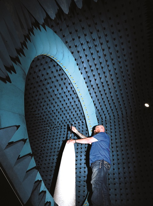
One is pattern and gain testing, in which the antenna’s radiation pattern and gain are precisely measured in a controlled environment (usually an anechoic chamber) to evaluate its ability to direct and focus energy at range during real-world missions.
In the US, facilities for pattern and gain tests must be traceable to, and compliant with, standards set by the National Institute of Standards and Technology (NIST).
Another is electrical testing, which gauges impedances, return losses and standing wave ratio (a parameter indicative of an impedance mismatch between the load and the internal impedance on the transmission line or waveguide, which can reduce power efficiency). A VNA is key to measuring these, and thus verifying that each unit will perform as needed at mission frequencies.
Lastly, environmental tests for shock, vibration, temperature and immersion across environmental chambers, rate tables and other well-established machinery are critical to certifying that antennas will last for their promised MTBF across the combination of mission, shipping and storage conditions, and unexpected physical or weather impacts.
As the effects of climate change worsen, uncrewed vehicles will need to endure worse extremes of temperature, precipitation, immersion, and so on, placing increased pressure on the manufacturers and integrators of antennas (and other components that typically mount external to vehicle hulls) to keep performing well under such conditions.
Future antenna technologies
Antennas evolve as an intersection of multiple scientific disciplines and industries – including radio, GNSS and cellular technologies – with various commercial, civil and military imperatives that stand to influence what tomorrow’s antennas must be designed for.
For instance, of particular interest to defence integrators is advanced beam steering, which enables antennas to dynamically direct their beams towards a receiver or away from sources of spoofing or jamming.

Of similar importance are null steering technologies, which create nulls in the direction of jammers to greatly reduce their efficacy against uncrewed vehicles. Antennas with such capabilities can now be made small and lightweight enough to integrate on a variety of UAVs, but these often function in just one or two bands.
The development of triple-band, null-steering antennas is now in progress and expected to yield fruit within the next year or so.
As both commercial and military vehicles operate in increasingly congested frequency environments, antennas designed to work with UWB radios (which transmit data over a wide band of frequencies with very low-power density and chance of interference with other signals) will be prized for their use in ensuring accurate comms at range with a lowered risk of interception or jamming.
UWB radio and antenna technology may also enable precise positioning and ranging with centimetre-accurate localisation, surpassing some traditional approaches to GNSS systems.
Meanwhile, the adoption of new-generation satnav constellations, such as the US’s GPS L5 and the EU’s Galileo E6, as well as regional systems such as NavIC in India, will soon provide uncrewed vehicles with improvements in position accuracy and signal strength, as well as enhanced signal reception reliability, with less susceptibility to spoofing, multipathing and congestion-driven interference.
Applications such as photogrammetry, agriculture, and search and rescue depend on highly precise positioning, so antennas with the right filtering arrangements for such frequencies will be especially prized in vehicles destined for these markets. NavIC is notably challenging in this regard due to transmitting in the S-band – an unusual quality for GNSS constellations, which are typically L band systems (and newer satellites all work in the lower L band) – so antennas tuned for receiving NavIC signals are best sought in India.
Despite all of this, artificial intelligence (AI) may yet prove to be the biggest untapped source of potential for improving antennas’ gain, signal integrity, bandwidth utilisation and interference mitigation. Signal-processing software trained through AI can sense changing signal conditions, indicative of obstacles in radiation paths, alterations in vehicle orientation or the sudden crowding of frequency bands. It can then react by toggling the antenna’s beam steering or null steering, or switching temporarily to new comms protocols or frequencies, or to different navigational inputs.
Whether generative AI could also be used during antenna production to, for example, shorten design and testing turnaround times by predictively simulating completed blueprints or data sets (as is being done for some parts of crewed vehicles) remains to be seen.

Either way, creative use of AI will spell more robust and flexible antenna integrations, which are a vital step forwards for uncrewed systems, no matter the operation.
Acknowledgements
For their help in researching this article, the author would like to thank: Colin Tomlin and Nigel Lee at Videosys Broadcast; Ed Norse at Trimble; Ken MacLeod, Julien Hautcoeur and Joseph Botros at Calian; Brad Carraway at Silvus Technologies; Austin Farnham at Octane Wireless; Manuel Marbach at Pidso; Javier Espuch at Embention; Brent Miller and Ben Baranek at MP Antenna; Jeremy Wischmeyer at Southwest Antennas; and Sean Casey at Doodle Labs.

UPCOMING EVENTS


