


ACC Thunder Wasp UAV
One Swedish company is poised for series production of its flagship quadrotor, which uses a gas turbine to lift weighty payloads, as Rory Jackson reports
Across land and sea, industry is crying out for ever-safer and more efficient heavy-lifting capabilities. UAVs represent the promise of highly flexible and cost-effective logistics: an uncrewed heavy lifter for picking up anything and placing it anywhere. However, the most prolific UAVs are still too costly to convince many parties to make the switch away from crewed helicopters.
The ambition to create something as capable as crewed helicopters, but safer and less costly, was what drove the founding of ACC Innovation. The company is a direct subsidiary of ACC Group, headquartered in Åtvidaberg in Sweden, roughly 2.5 hours from Stockholm, and close to the Swedish aeronautical capital of Linköping.
The group was founded in the early 21st century by Claes Drougge and his wife, and it includes Ocean Modules Sweden AB, Drougge’s ROV development and manufacturing company, which has operated for 24 years and continues to sell ROVs – currently more than 300 around the world.
Today, Claes has leveraged his previous experience as chairman of UAV helicopter company CybAero to enable ACC Innovation to fulfil the market gap for cost-effective, certifiable, autonomous heavy-lifting aircraft. With him as CEO (and son Max as CTO) of ACC Innovation, the Swedish company is poised for series production of its flagship product, the Thunder Wasp GT (Gas Turbine).
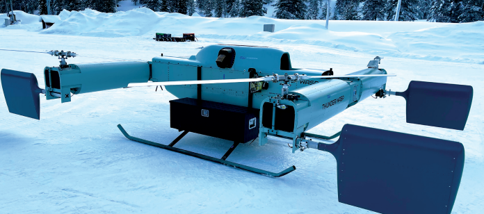
The Thunder Wasp GT is a quadrotor with an 800 kg MTOW, or an empty weight of 375 kg. Across the spare 425 kg, up to 248 kg of fuel may be stored, which gives just under four hours of flight time when the remaining 177 kg is taken by payload weight. Alternatively, if looking to maximise payload weight in a single trip, one may place up to 400 kg of payload onboard and get roughly 20 minutes of flight time.
Most unusually, the quadrotor does not fly on electric lift motors. Its gas turboshaft engine drives its four rotors via a transmission, with each rotor also functioning with its own variable-pitch propeller and downstream rudder, to optimise the propulsion for efficient VTOL, hovering, banking or cruising at 70-90 kph.
“Before starting development of this, our first UAV, we toured around the world to research what was being designed or built. No-one was developing anything quite like this, because it was deemed either too expensive, too complicated or too heavy. There were other claims, but those were the three main reasons,” Claes says.
“So, in 2016, we resolved to make a technical solution that would be affordable, lightweight and reliable. We brainstormed a few ideas for a year and a half in a closed room before patenting them, two of which cover a couple of powertrain configurations that are the key to how we can build such big and powerful drones.”
The first of those two patents covers the propulsion technology of the Thunder Wasp GT, the other three UAVs announced by ACC so far, and anything else it may build up to 2 t payload capacity. The second patent covers UAV powertrains of higher lifting capacities. It has been explored in laboratory and ground tests, with commercial exploration planned three to five years down the line.
As well as both Drougges drawing upon considerable prior engineering experience, sustainable self-funding of ACC Innovation’s work (via profits from Ocean Modules Sweden AB and other successful ACC Group ventures) has enabled development of the large, turbine-powered quadcopter.
Three units of the Thunder Wasp GT have been built, with 3.5 years of operation and over 100 test-flight hours (and over 700 takeoffs and landings) accumulated. As of writing, the company is focused on building three more units, as well as two Dragonfly (a smaller and differently configured quadrotor powered by a piston engine) – not for testing but sales purposes, and to research firsthand how best to transition from making individual units to series production.
Series production will start properly in January 2025. Of the completed units, one will be delivered to ACC’s new partner, Fireswarm Solutions, in Canada (which has dedicated itself to distributing Thunder Wasp GTs for autonomous firefighting in North America), with another going to an unnamed defence customer.
Strength, stiffness, simplicity
Three criteria stand out to the Drougges as having been paramount development targets for the Thunder Wasp GT. One was robustness, in terms of fault-tolerant and failure-proof operations, ideally to achieve failure rates even lower than those of crewed passenger aircraft.
“Uncrewed systems will be everywhere within the next 10 years, but if a pioneering system fails mid-flight it could set advancements in certification and funding back by years, so UAVs can’t function as well as crewed aeroplanes do. We really have to be better,” Claes says.
For instance, when ACC first started prototyping, carbon composite was treated by most of the industry as a miracle material, so the earliest versions of the Thunder Wasp were built mostly with carbon parts, but when the team accidentally dropped a screwdriver onto one of the UAV’s pylon hulls it caused a small crack in the carbon.
“That meant replacing the entire panel,” Claes says. “You can never repair a broken carbon body piece; you can’t undo a delamination or similar level of damage to the structural integrity of your craft, but aluminium can be directly hit with a hammer. It will certainly buckle, but it changes practically nothing of the lifespan or integrity of the UAV. You can just cut out the bent part of the metal and put a riveted cover over it. It’s field-repairable, as a multicopter should be in serious operations.”
Also critical was simplicity, which Claes notes is difficult to engineer. But he and his crew envisioned creating a UAV that could be handled by one person wearing gloves in a -20 C snowstorm, so mechanical and conceptual simplicity were taken into account with every drawing, iteration and modification.
“Engineers can make vehicles with amazing capabilities if they just make them as complicated as they like, but that means extremely high costs, lengthy manufacturing times and onerous certification processes,” Claes says.
“So, achieving simplicity has required testing and validating a few very good ideas, and also using COTS products. That might sound very different to using many customised components, like other uncrewed systems manufacturers do, but it greatly reduces our costs compared with using bespoke devices.
“And, more importantly, it means our subsystems have largely been out in the industry for years, made mature and reliable through hundreds of thousands of operating hours, meaning they’re also extremely well-documented for traceability and certification processes.”
Lastly, alongside development of the uncrewed aircraft, considerable money has been invested in developing effective patents to protect ACC Innovation’s IP, provide comprehensible technical explanations of it to interested customers or investors, and to not accidentally tread on the content of anyone else’s patents.
With these guiding principles, the first Thunder Wasp prototype was built in 2019, using carbon fibre, as well as a significant amount of glass fibre, and a Hayabusa engine. Lacking the company’s desired physical robustness, the next version was built around a welded chassis composed of 0.8 mm-thick, flight-certified, square steel tubes, with carbon-composite covers forming the body over the steel skeleton.
“But we couldn’t make it simple to assemble, or achieve the stiffness and strength we wanted, so we moved to using riveted aluminium sheets, as have been used in aviation since the 1940s, and are still used in most professional aircraft engineering and manufacturing today,” Claes recounts.
The third rendition started with rudimentary boxes of aluminium sheet, and after highly promising initial tests, a further version was built with sheets of dual aluminium sandwiching a foam core. While this increased strength and stiffness, the added manufacturing complexity was ultimately deemed excessive, with aluminium sheets alone being sufficiently strong, very lightweight and incredibly easy to work with.
“Today, we build nearly every structural part with 0.4 mm-thick aluminium sheets, which is almost as thin as kitchen foil, but when we put them together to construct a Thunder Wasp, they’re really very stiff and strong,” Claes says.
“We brought in a top carbon fibre expert to judge if we would benefit from switching to carbon fibre. In less than five minutes of inspecting the Thunder Wasp GT, he told us to keep doing what we were doing: he could see no way of improving it with carbon.”
H marks the spot
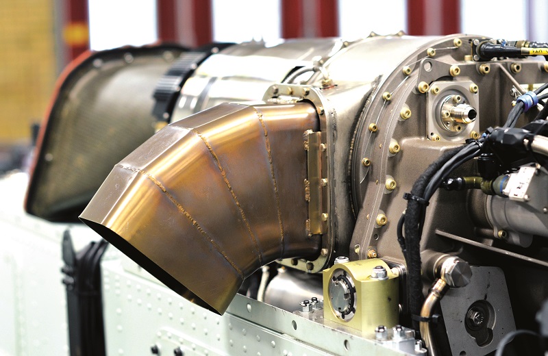
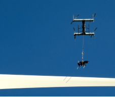
Looking down at the Thunder Wasp GT from above, the fuselage takes the shape of a large, metallic ‘H’, with each of the four corners mounting a single rotor for propulsion, as well as rudders for attitude and yaw control, and a gas turbine engine mounted atop the middle of the central bridge portion of the fuselage that joins the two ‘rotor pylons’.
The autopilot is placed inside that central portion, as close to the middle (and the CoG) as possible for accurate flight control, behind a riveted panel that can be removed for easy diagnostics or replacement of the autopilot.
Two CAN buses extend from the autopilot: one for the engine, and one for the avionics and data network, both of which can be accessed by technicians anywhere along the aircraft anatomy.
GNSS antennas for redundancy and heading are located atop the front and rear, equidistant between the reach of the rotor-blade tips, to keep the propellers from blocking nav-critical signals from space.
“Having a distance between those antennas is key for GNSS compassing, and additional antennas for comms are placed between our landing struts at the front and back,” says Max.
“The CAN buses extend down to those antennas, and the ubiquitousness of the CAN network means extra servos or payloads can be mounted quite flexibly across the airframe, depending on application.”
Along from the engine is an external, belt-driven alternator, which can provide up to 1 kW of electric power, but ACC reports that the engine’s internal generator has proven sufficient to date for powering all flight-critical systems.
A single, 4 kg, 15.6 Ah battery from EarthX in the US is installed under the engine, providing up to 840 A for starting power. It can also give emergency power to avionics in the event of generator breakdown, being a secure component based on LFP-type cells.
The bulk of onboard energy comes from a mission-changeable, structural fuel tank in the bottom half of the central bridge of the body. “An extended output shaft from the engine sticks out further along, which we could easily mount something like a 5 kW generator on, if a customer needed that,” Claes adds.
“Though this UAV [shown to us during our interview] has the engine exposed and visible, typically an aluminium fairing is riveted on top, safely enclosing it against external elements and making the aircraft look much nicer, although we tend not to use it in test flights, just so we can observe and access the engine easily.”
Also key to test-flight observations are a number of GoPro cameras at the landing struts, inside the body and throughout the fuselage, which are installed to visually study every part of the UAV at each flight stage.
Airframe validation
While virtually every fairing and bulkhead is made strong and lightweight with the 0.4 mm-thick aluminium sheet, the airframe design has been developed to achieve a non-complex construction, a modicum of aerodynamics and a professional-looking aesthetic.
“Obviously, the Thunder Wasp GT isn’t a high-speed aircraft. You can cruise 70-90 kph, but it’s a heavy-lifting crane in the sky, so the aero is just for smooth flight and some energy efficiency gains. Our Dragonfly UAVs will cruise at 150 kph and carry 200 kg for just two or three hours, but that’s a different use-case,” Claes says.
In addition to considerable research in Solidworks, aerodynamic optimisations have been achieved using a test bench built in-house for trialling either one Thunder Wasp rotor or one rotor pylon with its two rotors integrated, which measures torque, thrust, rpm, efficiencies at different blade-pitch angles and myriad other parameters in advance of test flights. Rotors have also been mounted on road vehicles and driven down runways to simulate wind tunnels in outdoor conditions, as we have seen other developers do.
“Though making a test bench for a unique aircraft construction isn’t easy, we did account for available regulations in designing it, which will be hugely helpful for certification in due course, given that no specific certification regulations exist for this type of large, heavy-lifting UAV just yet,” Max adds.
Also key to that will be ACC’s own flight range, roughly 400 m away from its headquarters, which was approved by Transportstyrelsen (the Swedish Transport Agency) in March 2024. It has enabled rapid testing and evaluation of new iterations, modifications and components in the company’s UAVs over the past year.

Industrigallerian
However, the ACC Group’s headquarters may be the biggest reason why ACC Innovation is making it to series production and working towards Type Certification after just five years of physical r&d (other, larger OEMs have tried for longer, only for their uncrewed ventures to fall by the wayside).
“We followed a clear plan, and one target was for our first UAV series-manufacturing space to be ready by the start of the winter holiday in 2024. We hit our deadline, so now we have a brand new production facility here, with laboratory levels of cleanliness and traceability,” Claes says.
“As mentioned, we’re working on three Thunder Wasp GTs and two Dragonfly to learn firsthand how best to organise our series production, but a critical partner we’re doing that with is Scanfil Åtvidaberg AB, which will be the contract manufacturer, set to do the series production once we’ve determined how it should be done.”
Finland-headquartered Scanfil is one of Europe’s largest contract manufacturers (with over 3500 staff and a turnover of $1 bn). Its subsidiary, Scanfil Åtvidaberg AB, is one of several companies renting factory space in Industrigallerian – the industrial business residence of ACC Group, located in Åtvidaberg – within which about 370 Scanfil staff work to manufacture other types of large UAVs, and other products.
“Manufacturing our series here – while also having 15 other companies, including 80% of our sub-suppliers here in Industrigallerian, and doing our r&d here to keep innovating and staying ahead of the curve – means we have a nice, closed loop in this building,” Claes says. “We could not have gotten our development to this brink of series manufacturing and certification without such resources here at our fingertips.”
He adds that despite being entirely self-funded to date, a small portion of ownership will be sold to fund the starting costs of series production and to grow the company, particularly the number of staff for tech development, flight operations and sales.
One machine already acquired is a large Trumpf laser cutter, to be operated by fellow Industrigallerian resident Minec Produktion AB, which has functioned as a CNC machining specialist to ACC Innovation and will continue as such.
“That will be one of the largest cutting machines in Sweden. The worktable is around 4 m long and 2 m wide, so that will be really helpful, not just for the Thunder Wasp GT, but also for other, bigger UAVs we’ll start prototyping five to 10 years in the future,” Claes says.
ACC’s manufacturing centre
The production area is a closed space, cordoned off from the rest of the building by a set of 25 cm-thick sound isolation walls. The centre of the production floor features a large, open space for all serial-numbered components to be stocked on shelves, retrieved and laid out in preparation for the assembly of a new UAV.
These are largely pieces of aluminium for the body panels and bulkheads, which are made via a combination of laser and waterjet cutting, with ACC currently evaluating both processes for the best application in series production (laser cutting is potentially 20 times faster, but does require more rigorous programming, as well as significant stock of nitrogen for cooling to prevent thermal expansion in the metal).
Four smaller, isolated rooms run in sequence along the length of the manufacturing floor, each one dedicated to a different stage of aircraft manufacturing.
In the first room, rotor pylons are assembled; a process facilitated by a 1 t iron jig. Before riveting any aluminium sheets, ACC’s production staff will affix them to this jig, preventing any unintended bends being allowed into the body geometry, which would mean unwanted tension in the pylons.
Claes demonstrated the risk of this problem by hand-lifting a large, 0.4 mm aluminium sheet for us, with it visibly flexing and wobbling under its own inertia when not held by rivets or tabs, as it is in the Thunder Wasp. For comparison, he then hand-lifted an assembled rotor pylon, which exhibited no flexing.
The complete fuselages (including the central bridge section) are put together in the second room, also on a jig, before being moved to room four, where the complete UAV will be assembled.

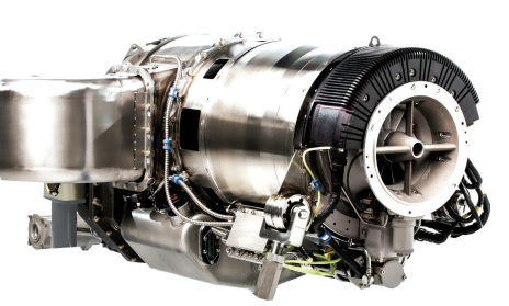
In the third room, the fuel tank is put together on another jig. The fourth room exists for the rotor systems and powertrains themselves to be installed in the pylons, and, as of writing, the engines are stocked here accordingly. Claes and Max showed us one unit of the engine, a TS100 from Czechia’s PBS Group, environmentally sealed in a vacuum bag in one of six identical crates.
“Those six engines are our total stock of them at the moment,” Claes says. “It’s one of our most costly subsystems, but the power output and performance consistency are both very good for our purposes.”
Once a UAV has passed through all four rooms, it is rolled out to the open area for systems integration and electrical installations. In a separate prototype workshop, the aircraft are allowed to be test-run at full power. They can be weighed down with concrete blocks for simulating real-world payload masses, with gas conduits for pumping exhaust safely out of the building and away from ACC’s people (and the aforementioned rotor test rig also sits in this room).
“We will also test surplus rotor pylons here, running them on a test UAV to validate them. If the pylon passes those performance checks, we can remove it and put it in stock until it is needed for assembly into a sold unit,” Claes says.
To remove a pylon for stock, maintenance checks and repairs, or when collapsing a Thunder Wasp for transport, an electrical connector running to the servos is first disconnected, roughly where the bridge and pylon meet. Then, 12 bolts around the pylon’s mid-section can be removed, after which the pylon slides off the bridge end. It can then be carried by one person to a specified room or fitted in a standard road van.
Heavy fuel turbo
As mentioned, the engine at the heart of the Thunder Wasp GT is PBS Group’s TS100, which has a peak power output of 241 bhp (180 kW) and a maximum continuous output of 214 bhp (160 kW) at which it has an SFC of 0.863 lb/hp/hr (524.94 g/kWh), with a typical operating fuel consumption of 67 kg/h, and a top output shaft speed of 2158 rpm for driving the transmission to the rotors, which run at roughly 1650 rpm.
The 61.2 kg turbine engine measures 39.8 cm tall, 33 cm wide and 82.8 cm long, and it comes with an integral power turbine, gearbox and a 1 kW electric generator, of which 720 W may be used by the aircraft itself.
“PBS is known for good engine design and expertise, plus this engine had exactly the performance we needed and proved very simple to control via its integrated ECU,” Max says.
“We integrated its CANaerospace protocol into our autopilot, and that gives an interface with all the dials and gauges showing engine speeds, torque, temperature and other parameters, as well as the simple ability to send ‘start’, ‘Idle 1’, ‘Idle 2’, ‘Flight’ and other mode commands to the engine. Once landed, we can, for example, select ‘Stop’ and it will automatically engage its own cooling procedures.”
Claes adds: “As well as that user-friendliness fitting our philosophy that everything should be simple, its TBO is 1500 hours. That’s really special, especially among smaller turbines, which are too often made for target drones, and therefore way too small and shortlived.”
In addition to providing a simplified user experience, the ECU keeps logs of all health and performance parameters, which can be extracted and examined seamlessly for diagnosing any issues that may arise.
The underbelly fuel tank can hold up to 310 L of liquid, or roughly 248 kg, despite the entire tank assembly weighing only 6 kg. It divides into six sections, separated by valves to prevent unwanted flow in between. A collector tank also sits within the tank, designed with overpressure to ensure a positive pressure of fuel for delivery to the gas turbine. The system can run on various fuels, including Jet A and A1, although ACC preferentially opts for A1.
“We have three fuel pumps: two pump fuel from the large tank below into the collector tank above, and the third pumps fuel directly into the engine’s injector manifold from the catch tank,” Max explains.
“The idea is that the two former pumps build up pressure to feed the engine in the event of the third pump getting damaged, and small holes atop the collector tank gradually overflow to eliminate any air bubbles. Another important function of the fuel tank is to always ensure the engine sucks fuel from a full tank, even when doing large flight manoeuvres. To track all of that we have fuel-flow sensors tracking flow into the collector tank and into the engine.”
Transmission arrangement
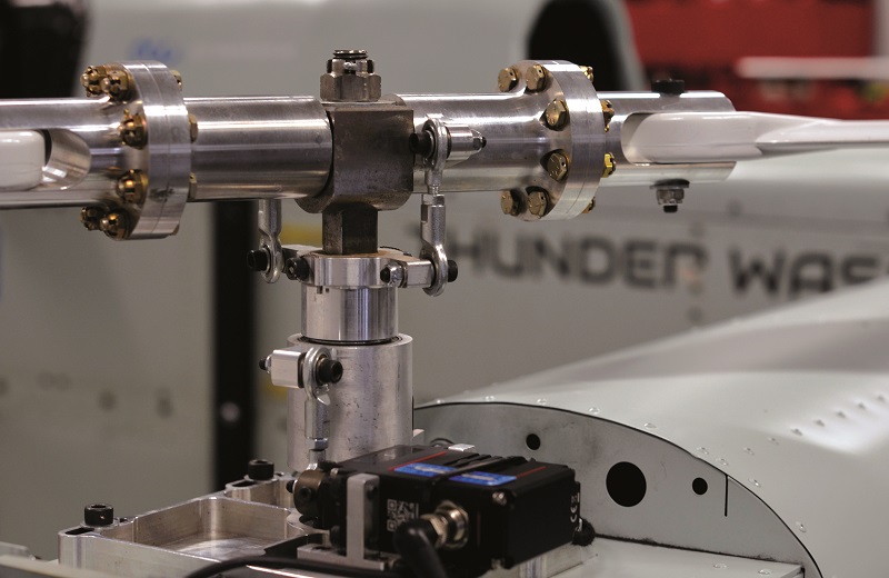
From the engine shaft, power is distributed out to the pylons and rotors, such that if a single propeller is grabbed and rotated by hand, the other three rotate in parallel.
“The TS100’s output shaft connects to a main transmission shaft, which runs the entire length of the fuselage, and at either end of the main transmission is a claw coupling, which is key to how we’re able to easily remove or reinstall the pylon,” Max explains.
“A driven claw coupling inside the pylon mid-section connects to our proprietary, mechanical driveline, which runs through to the rotors – that is a technology that’s going to be used in every ACC UAV in the coming years; we can’t talk in detail about that, however. The rotor systems themselves are somewhat analogous to a helicopter’s tail rotor.”
Claes muses: “We can say there’s no gearboxes other than that inside the PBS engine, because transmission gearboxes are the most sensitive part in helicopters, really prone to overheating and breaking down, but for anyone in disbelief at how our driveline can function without gearboxes, we’re happy to have them over for a visit, so they can see it for themselves. We just don’t release anything about it publicly for now.”
Constant speed rotors
ACC did not want four electric rotors, as per conventional quadrotor designs, due to physics-related limitations on scaling up to the Thunder Wasp GT’s lifting capacity. To change thrust, the propeller on an electric motor must accelerate or decelerate, but in a heavy-lifting UAV, there is significant propeller and motor mass that needs to be accelerated or decelerated, which translates into slower control response times and inefficiencies.
Instead, the Thunder Wasp runs on variable-pitch props at a constant rpm. The blades’ pitches respond with near-instantaneous timing to autopilot commands, able to agilely increase their angle of attack for lifting, flattening it for hover and decreasing it for descent.
The pitch of each carbon-composite blade pair is collectively controlled via a dedicated, electromechanical servo, ACC forgoing swashplates and similar components that can be troublesome in helicopter drivetrains, and would have interfered with the goal of mechanical simplicity.
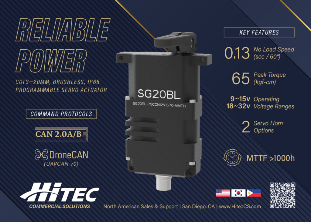
A single pitch servo is bolted atop each of the four pylons’ outer edges, with stainless-steel gear servos from Hitec used in this UAV (such gear types being critical for servo longevity and consistency), with four of the company’s SG33BLTs providing pitch control via their 1441.2 N/cm of max torque output.
“Each pitch servo acts on a rod end bearing, which runs up to a plate sleeve, which mechanically links to and drives two further rods extending upwards. Each of those connects at their tops to a respective link for one of the rotor blades,” Max says.
“When you push or pull the rod end bearing, the transmission pushes or pulls the two upper rods to crank and hence rotate the blade links in opposing directions, thereby increasing or decreasing both blades’ pitches in equal measure. If we’d gone with a swashplate, we could adjust prop pitch in any direction freely, but swashplates have to be constantly checked, adjusted and overhauled frequently.”
Rudders in the air
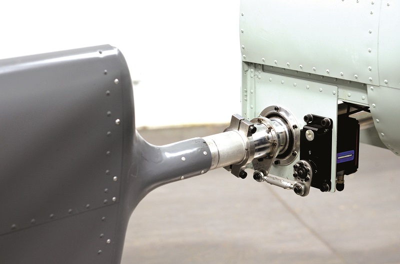
Each propeller has its own rudder, which sits below and downstream of the rotor blades, to catch on their airflow and adjust the attitude of the whole vehicle.
“After conceiving them, we designed them, built them and integrated control subroutines for them into the software, all in less than three weeks,” Claes says. “They allow the UAV to pitch, roll and yaw as gently or sharply as we might need.”
The team discovered afterwards through testing that, given how the rudders adjust the UAV’s attitude with ‘used air’ from the propellers, rather than needing to drive some rotors harder (requiring a thrust headroom of around 20% on each rotor) for attitude changes, as in conventional multirotors, the power efficiency and lifting capacity of the Thunder Wasp remains comparatively unchanged during operation.
“When you combine the fast blade-pitch response with the rudders, you can see from the videos on our website that the Thunder Wasp GT can really roll, pitch and yaw, just like a regular FPV drone, even weighing 800 kg,” Max says.
“We don’t typically run it like that since our applications don’t exactly require it, but if we wanted we could even, theoretically, fly it upside down.”
A rudder servo is mounted under the outermost portion of each pylon. Together with the pitch servos, that makes for a total of eight servos as standard across the Thunder Wasp GT.
Hitec’s SG50BL actuates the rudders; its capacity for up to 5098 N/cm of torque being key to achieving exact angles and movements for the rudders against potentially very strong winds.
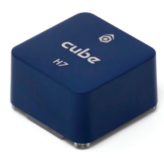
Little blue cube
CubePilot’s Cube Blue H7 and the Ardupilot library of open-source algorithms have satisfied the performance and engineering flexibility requirements for the Thunder Wasp’s flight computing and automatic navigation to date. ACC chose the Blue H7 for being CubePilot’s highest-end solution, which is made in America with allied countries’ components, at the time of development.
“We’re now considering the Cube Red, not just because it is their latest product, but also because it’s a redundant system with mirrored processors. If one goes down, you still have full control over the UAV, which is excellent for safety, flight permits and certifications,” Max says.
“Cube Red also comes with Ethernet support and a third CAN bus, as well as better IMUs and other subcomponents.”
An RTK GPS receiver from ARK Electronics typically combines with the Cube Blue’s inertial sensors for navigation, with data running over a DroneCAN connection from the autopilot, which links to all external avionics across the aircraft, enabling control and diagnostics of all critical systems (particularly the servos, traditionally the first component to break on any aircraft). A second CANaerospace bus links the autopilot to the gas turbine.
Most algos for automatic behaviours – including VTOL, hovering, GNSS waypoint following, and engine startup and shutdown – come pre-integrated in the Cube’s Ardupilot software.
As of writing, other AI behaviours are being explored by Fireswarm Solutions, particularly in swarming up to five Thunder Wasps from one GCS and the use of real-time EO/IR data to define flight manoeuvres, as well as optimal locations to drop water for extinguishing wildfires. These will be implemented via an added algorithmic layer atop the present Ardupilot architecture, enabling fully autonomous aerial-firefighting.
“The GoPro cameras we use for testing could theoretically provide a visual navigation system, with Ardupilot algorithms easily available for that sort of thing, but an Nvidia companion computer would probably be best to integrate for processing the camera data in real time,” Max adds.
Navigation and data links
Although ARK’s RTK GPS receiver is used, being compatible with DroneCAN and running on a Ublox F9P GPS chip, as well as a Bosch barometer and magnetometer, any navigation systems and communications links can theoretically be used.
CubePilot’s Herelink is used during testing as a plug-and-play data link, although the company has also used comms systems from Radionor at the higher end and from RFDesign in more cost-optimised operations.
For BVLOS, ACC expresses particular appreciation for Starlink’s consistent global coverage (versus VLOS links, which are more easily disrupted by occlusion from forests or mountains), as well as its 20 Mbit/s uplink and 50-100 ms latency.
“The Cube has inbuilt ADS-B In for air-traffic awareness, but we can easily integrate transponders as needed. EASA mandates remote-ID in some instances and we’re potentially interested in some of the Ping products from uAvionix,” Max says.
Ground control
The UAV’s standard GCS is a custom system from Desert Rotor in the US, resemblant of its MIRA X HOTAS product by virtue of it being a case-integrated, ruggedised computer system. The case lid integrates the monitor, while the other half features a keyboard, joystick and numerous other toggles for flight modes, payload releases, throttle, optional gimbal controls and further functions. The PC hardware is enclosed below the user interface, accessible under the keyboard (which sits in a hinged hatch that snap-releases to swing open).
“We also have several Ethernet and USB ports, as well as four data-link antenna connectors. The manual toggles are separated from the PC, going straight to a dedicated system and then the data links, so if the PC dies we can still have remote control over the UAV,” Max says.
Any power supply of 230 V, 110 V or other voltages (mains or generators) can run into the GCS to power it, although an onboard battery is also integrated in case of external power failure.
Payload
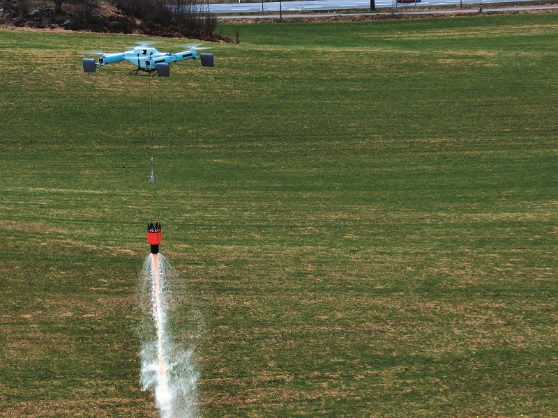
Rather than using a winch for raising and lowering firefighting payloads, the entire Thunder Wasp lowers itself, avoiding the weight and potential mechanical failure of a winch. Thus, to lower a bucket closer to a fire, it lowers itself.
A chain is connected to the UAV via a servo-actuated emergency release system, controlled via DroneCAN (not counted among the eight flight-control servos due to being mission-specific), which, in case of emergency, can drop the entire load.
The bambi-bucket is controlled by a relay, which then enables energisation or de-energisation of a solenoid, which then opens the bucket and releases the water.
Camera payloads typically integrate to the autopilot via MAVLink, with video transferable via Ethernet or HDMI, and mechanical integration is recommended at the sides of the fuel tank for clear views and stable weight distribution. Downward-facing laser rangefinders have also previously been integrated in a similar manner.
Upcoming firefighting missions will see Thunder Wasps equipped with airborne radars and thermal cameras – the latter helping with fire analysis, and both being key to obstacle avoidance in poor visibility conditions caused by smoke.
Future
In broad strokes, ACC Innovation’s plans encompass raising up “a new aircraft industry” in Sweden, starting with series production of its low-speed, heavy-lifting Thunder Wasp GT – including models coded as 2xGT, equipping two PBS TS100 engines on a common shaft for 2 t of lifting capacity – and its upcoming Dragonfly as a higher-speed lifter.
“We expect to produce a large number of both of these over the next three to five years – hundreds or potentially thousands – even ignoring the direct interest we have received, and just basing expectations on how much mass they can move, and how far and long they can move it, relative to the cost of operating it,” Claes says.
The company will focus particularly on windfarm fields, firefighting and defence, with the former two especially easy to access given their dedication to green technologies, such as the fuel-efficient Thunder Wasp GT.
As well as its two models discussed so far, ACC anticipates introducing either a new UAV design or an update on an existing model to leverage new technologies every two to three years.
“We have maybe 10 different aircraft concepts to evaluate in our pipeline, with specific plans to explore them over the next five to 10 years, linked to how the market is expected to grow in that time,” Claes adds. “Everything we need will either be produced or heavily stocked in this building, so we can iterate and trial new designs very quickly to suit any application that our patented technologies could make a difference in.”
Acknowledgements
ACC Innovation would like to give a special thanks to the ArduPilot team, particularly Leonard Hall of Freespace Solutions Pty, Peter Hall of KH Unmanned and Andrew Tridgell.
Key specifications
- Thunder Wasp GT
- Quadrotor
- Gas turbine (Jet A1)
- Mechanical rotor transmission
- Aluminium structure
- MTOW: 800 kg
- Empty weight: 375 kg
- Max payload: 400 kg
- Nominal fuel capacity: 248 kg
- Nominal flight endurance (with standard fuel tank): 3.5 hours
- Cruising speed range: 70-90 kph
- Max airspeed: 110 kph depending on configuration
- Service ceiling: 3000 m ASL (ISA)
Some key suppliers
- Gas turbine powertrains: PBS Group
- Rotor blades: HAB
- Servos: Hitec
- Autopilot computers: CubePilot
- Autopilot software: Ardupilot
- RTK GPS receivers: ARK Electronics
- Satcom: Starlink
- Data links: CubePilot
- Data links: Doodle Labs
- Data links: Radionor
- Data links: RFDesign
- Cabling: Novael Production AB
- Batteries: EarthX Batteries
- GCSs: Desert Rotor
- CNC laser-cutting services: Minec Produktion AB
- CNC waterjet cutting services: Maskinteknik i Orskarshamn AB
- Laser cutter: Trumpf
- Contract manufacturer: Scanfil Åtvidaberg AB
UPCOMING EVENTS


