


CyloTech Bumblebee 2.0
Peter Donaldson explores a unique flight system inspired by a century-old water propeller
There is a lot of overlap between uncrewed aerial vehicles (UAVs) and electric vehicle take-off and landing (eVTOL) aircraft intended to carry people, most of which is a result of technology transfer from one to the other. In the case of CycloTech, and its radical CycloRotor propulsion and control system, however, it is a new technology under development for both, even though early engineering work and flight testing is focused on uncrewed prototypes, the latest being the Bumblebee 2.0.
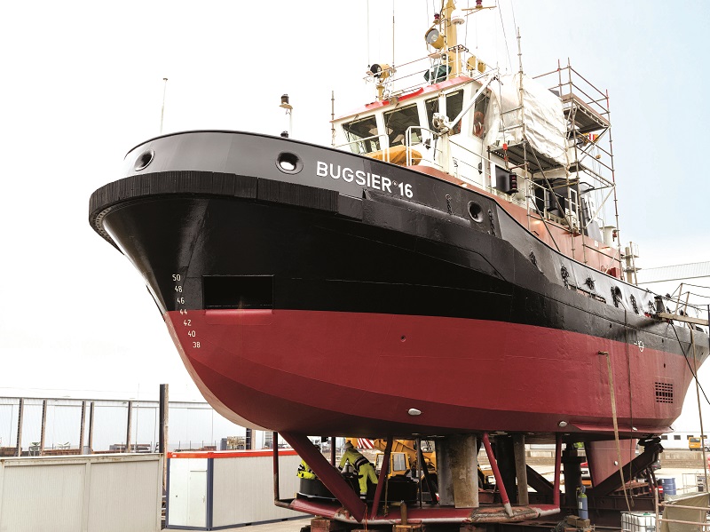
The CycloRotor is an adaptation of a concept developed almost a century ago and successfully applied to ships – the Voith Schneider cycloidal propeller, which uses vertically mounted blades arranged in a circle that revolve around a common centre and change pitch cyclically in concert to direct their thrust in any direction around their axis of rotation.
In this way, the propeller provides both propulsion and steering. It is used in ships that need to manoeuvre in tight spaces, follow a course precisely at low speed at sea or hold an exact position against strong currents. Common applications include ferries, tugs, cable layers, drill ships, offshore construction vessels, buoy tenders and river cruise ships.
The idea to apply this concept to an aircraft occurred to CycloTech’s founder, Meinhard Schwaiger, in the early 2000s while stuck in a Moscow traffic jam.
“He was convinced that things had to change for the better and that using the third dimension as additional axis for mobility would bring the expected relief,” says chief development officer Markus Steinke. “When researching technical options, he found the cycloidal rotor the most promising.” Schweiger founded the company in Linz, Austria in 2004.
The main differences between a CycloRotor (also known as a cyclogyro rotor) and the Voith Schneider propeller stem from the rather obvious fact that the former operates in air rather than water. In a standard atmosphere (1 atm at 20 C), water is about 800 times denser than air, which means the CycloRotor operates at much higher rotational speeds.
CycloRotors can be used as either main propulsion or auxiliary propulsion devices. If they are used as the main propulsion, their thrust-to-weight ratio is vital as they will have to lift the vehicle vertically into the air – not a feat that a marine propeller ever has to perform. They will provide lift, forward thrust and full vehicle motion control. No wings or control surfaces are needed.
Steinke explains: “They allow vehicle designs that are very compact and very manoeuvrable. Thus, they are the best fit for cargo drones, and even more so for ‘flying cars’ carrying people and flying autonomously.”
As an auxiliary propulsion system, CycloRotors can provide stability, precise steering and enhanced manoeuvrability, particularly in load-lifting applications such as flying cranes, he adds.
Steinke reports that CycloTech has had enquiries from companies in many countries, including Japan, the USA and the UK, for CycloRotors for use in main and auxiliary propulsion roles. While the basic principle is well established, the company holds US, European and Chinese patents covering novel details of the CycloRotor’s control mechanism and a vehicle/rotor combination.
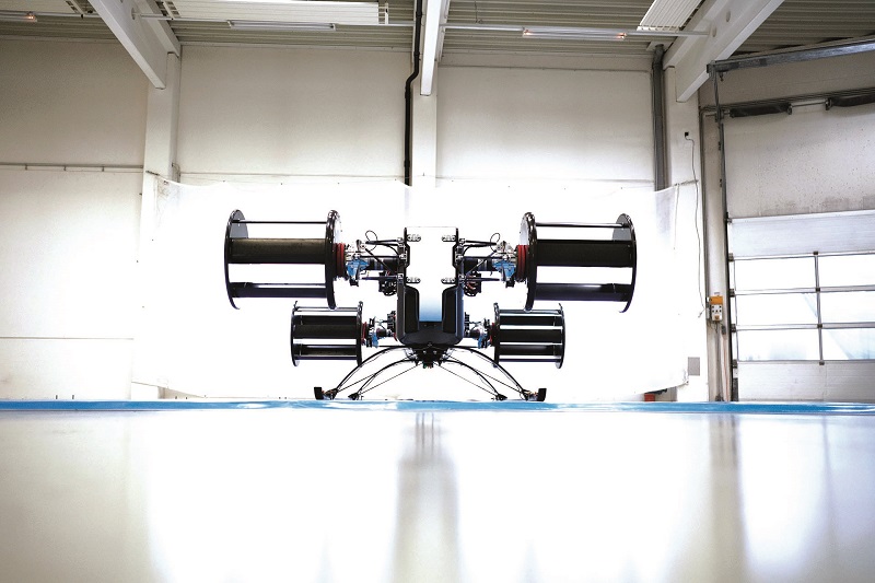
Bumblebee 2.0 is the second flying prototype and the successor to Bumblebee 1.0, which was used for indoor flight tests in 2021. The updated machine has reduced weight and an improved flight control system, and it is being used for open air flight tests.
“We will continue to expand the flight envelope incrementally until we reach the limits of the current capabilities of the demonstrator,” says Klemens Hofreither, chief engineer, aircraft. “We want to demonstrate the unique manoeuvre capabilities of a CycloRotor-equipped aircraft by showing the decoupling of the flight path and vehicle attitude at low speeds followed by a forward-flight campaign.”
Cyclogyro propulsion system
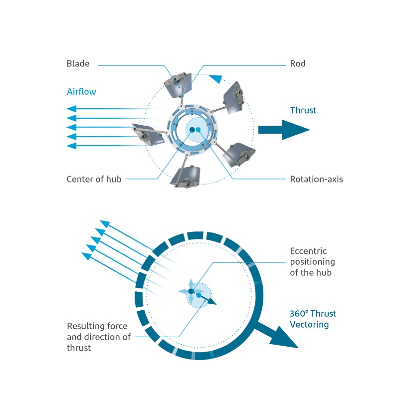
Hofreither explains how the system works: “A cyclogyro rotor contains a number of parallel blades rotating around a central axis. Each blade is mechanically connected to a central hub by a connecting rod. By moving the hub eccentrically from the axis of rotation of the rotor, the angle of attack of each blade changes periodically during a revolution. This accelerates the air through the rotor and generates thrust.
“The individual pitch angle of the blades is controlled by a pitch mechanism. The magnitude and direction of the cyclogyro rotor thrust can be directly controlled by the eccentric positioning of this hub.
“This provides a uniquely simple and fast way to control the thrust vector of the propulsion unit and change the position of the aircraft without tilting any of the aircraft structures – a capability that no other propulsion system offers.”
The exact details of the pitch-change system’s mechanics are closely guarded, but patent drawings illustrate the principle. A general arrangement drawing depicts a circular hub with a connecting rod pivoting on its perimeter and connecting to a second pivot on the blade, which is secured by a third pivot ahead of the second to the outer rim of the CycloRotor assembly, which is concentric with the hub. In this way, rotation of the hub either pulls or pushes on the aft pivot on the blade to change the pitch angle with respect to the outer rim.
Hofreither emphasises that the cyclogyro’s combination of 360° thrust vectoring with very quick control responses results from running the rotor at a constant speed and changing only the pitch of the blades. It also makes for a much more compact vehicle design, enabling missions for which comparable air vehicles are too large.
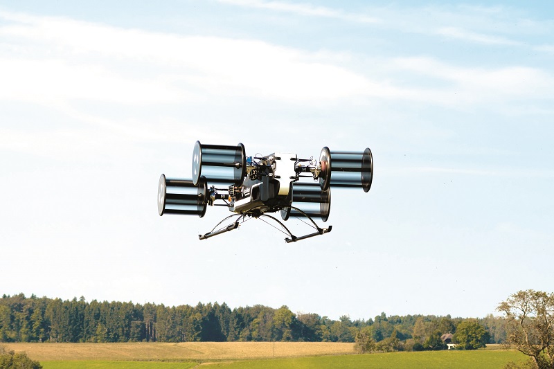
With a pair of rotors at each end, spinning on axes parallel to the aircraft’s pitch axis, Bumblebee 2.0 can be manoeuvred around and along its pitch, roll and yaw axes, giving it six degrees of freedom. The aircraft can also turn without rolling, keeping the fuselage horizontal through 360° turns in either direction if necessary.
Asked about the technical challenges to be faced in the development of the technology, Hofreither says the toughest task is achieving the necessary thrust-to-weight ratio, along with sufficient rotor efficiency to realise a battery powered eVTOL machine using mainly off-the-shelf drivetrain components, apart from the rotors.
The system’s most highly loaded components are the rotor blades and the pitch-change mechanism, so the safety of the system overall had to be considered carefully. As with other eVTOL machines, however, redundancy is ensured though distributed electric propulsion.
“With a sufficient number of CycloRotors on a vehicle, if one or two failures occur, the remaining rotors can safely control the vehicle,” Hofreither adds.
Powertrain and flight control
Each rotor is powered by an off-the-shelf electric motor from Lehner-Motoren-Technik combined with an in-house developed reduction gearbox and an electric speed controller from MGM COMPRO, which also supplies the battery management system (BMS) and bus contactors. In total, the propulsion system draws 40 kW peak power and 30 kW continuous power in the hover.
The battery itself is an in-house design, based on pouch cells that combine high power density with a “reasonable” energy density. The complete battery system weighs 18.7 kg and there is no onboard charger.
The pitch-change mechanism at the heart of the thrust vectoring capability consists of a set of rods connected to the blades and to a hub that surrounds the main axis of rotation but is free to move eccentrically in either direction around it.
The company chose to develop its own flight control system because off-the-shelf options could not handle the CycloRotor’s unique capabilities.
“Almost all flight control software currently on the market is made for either conventional aeroplanes or drones,” says Lukas Kinast, chief engineer, rotor. “None of them has a propulsion system capable of generating thrust through 360° and changing this thrust rapidly. In order to make the most of the cyclogyro rotor, the flight control system must be aware of that unique characteristic.”
While the Bumblebee 2.0 does not have an autopilot and is flown remotely by a human pilot, it does have an onboard controller that translates the pilot’s commands into movements of the pitch-change mechanism. This controller runs CycloTech’s own flight control algorithm, which is based on the well-proven Inner Loop Nonlinear Dynamic Inversion (INDI) method.
In flight control systems, the inner loop refers to the low-level control loop used to stabilise the aircraft and track commanded flight trajectories. It typically operates at high frequency to deal with the fast dynamics of the aircraft. The outer loop operates at a lower frequency and focuses on higher-level flight control tasks, such as trajectory planning, altitude control, navigation and mission management.
The dynamics of aircraft, particularly of unconventional VTOL machines, tend to be inherently nonlinear due, for example, to complex interactions between aerodynamic phenomena, propulsion-system behaviour and responses to control inputs. Dynamic inversion is a technique that approximates such nonlinear dynamics with a set of linearised equations to make control easier.
The resulting control laws generate commands based on the desired trajectory and the aircraft’s current state. They are designed to provide robustness against uncertainties in the system and disturbances encountered in flight, relying on feedback control that involves continuous measurement of the aircraft’s state, comparing it to the desired state and adjusting the control inputs to minimise the difference.
CycloTech is using a model-based controller design to develop its flight control algorithm. “Model-based controller development allows detailed tests and verification in simulation; namely, software-in-the-loop testing and hardware in the loop testing on different levels. Furthermore, the pilots can fly the aircraft directly in a flight simulator,” says Kinast.
The company has been working on flight dynamics for about four years with the University of the Federal Armed Forces in Munich, which Kinast describes as very fruitful for both sides. “Through that we are able to combine modern flight-control theories with the CycloRotor technology in the FCS [flight control system] – right from the start in the initial design and during its improvement over time.”
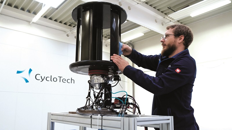
Materials and structure
The primary structure of the airframe consists of a layup of prepreg carbon fibre-reinforced polymer. The loads from the four CycloRotors are transferred to the structure through a suspension system with integrated damping capabilities. The landing gear is a conventional, skid-type design, similar to a helicopter’s landing gear. The only metals in the airframe are aluminium and titanium, used for inserts, brackets and fasteners.
With a maximum take-off weight of 85 kg, Bumblebee 2.0 is designed as a flying testbed for the company’s CycloRotor technology and is operated with a visual line of sight.
Testing times
Hofreither reports that Bumblebee 2.0 is making good progress in its test programme, having successfully completed a series of dynamic bench tests, along with free flights indoors and outdoors. In the flight tests it has demonstrated its ability to take off, achieve a stable hover, manoeuvre effectively, and land smoothly and precisely. He adds that the team has optimised the vehicle’s performance via an iterative, incremental approach to testing, logging more than 750 flights.
Rigorous data collection during the flight tests has provided valuable insights into Bumblebee 2.0’s performance and helped the team to optimise it. The telemetry system collects data from the propulsion units, the battery, the flight controller and other key aircraft systems.
This includes temperature, voltage, current, electrical power consumption, system status, aerodynamic pressure, aircraft height, position (GPS), speed, attitude and acceleration data.
“Step by step, we are expanding the flight envelope in testing, and gaining more and more knowledge about the unique capabilities of a CycloRotor-equipped aircraft,” Hofreither says.
“We have already explored more demanding environmental conditions than originally intended by flying in high temperatures and corresponding low air densities.”
Next, the team plans to show some of the vehicle’s unique manoeuvring capabilities. “For example, we want to perform a pitch manoeuvre to show the vehicle’s ability to decouple its attitude from its flight path,” he says.
In operation, this could be useful for landing on an inclined surface, as the vehicle could match its pitch angle to that of the slop and descend vertically, instead of having to touch one skid down before the other.
“Another example would be compensation for gusts or crosswinds without the need to pitch the whole aircraft, which is more responsive and has the potential for higher precision in positioning,” he says. It could also be used for aiming purposes in a military or firefighting context.
While testing Bumblebee 2.0 and then putting it through its paces for the public, the CycloTech team also has other future developments in mind.
Future directions
“Our focus is now on the next generation of CycloRotors, incorporating all that we have learned from further research, ground and flight testing,” Hofreither explains. “Any new demonstrator would feature a new generation of CycloRotors and a design with at least six of them to utilise their unique 360° thrust vectoring capabilities better.”
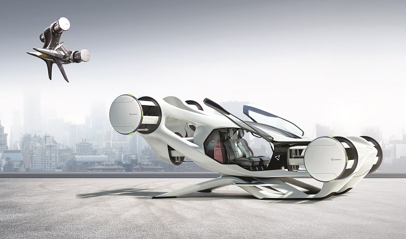
The company’s thinking on six-rotor machines can be seen in feasibility studies for vehicles such as the CruiseUp crewed eVTOL machine and the CCY-01 cargo UAV, the latter being the subject of a cooperative study with Yamato Holdings in Japan.
CruiseUp is conceived as a two-passenger, autonomous air-taxi with a top speed of 150 km/h and a range of 100 km. CCY-01 is described as a mid-class cargo eVTOL machine, capable of carrying a 45 kg payload for 40 km and coping with crosswinds of up to 36.5 kt. It occupies a 2.7 x 2.5 m ground footprint, easing operation to and from confined areas, particularly in urban environments.
A third concept is described as a very high-stability inspection UAV, illustrated as a quadcopter with a single CycloRotor module on top to provide direct horizontal thrust in any direction.
Each of these very different six-rotor aircraft places its extra pair of CycloRotors at a 90° angle to the other four, where they can generate thrust directly to the side, parallel with the pitch axis, in addition to contributing to lift.
This allows the aircraft to move laterally in a flat attitude, because there is no need to roll the aircraft to tilt the thrust vector to move sideways. As well as adding another decoupled axis for manoeuvre, it also increases the ability to counter lateral gusts, so the aircraft is much more stable in rough weather.
When the flight-test programme is over, Bumblebee 2.0 will become a flying showcase for CycloRotors and air vehicles equipped with them, and Steinke hopes it will “inform, impress and inspire” the rest of the world. “And, in the very end, it will find its place in a museum somewhere.”
Basic specifications
- Length: 2.468 m
- Width: 1.864 m
- Height: 0.897 m
- Max take-off weight: 85 kg
- Speed: up to 100 km/h
- Flight time: 10 min with current battery technology
Some key suppliers:
- Electric motors: Lehner-Motoren-Technik
- Electronic speed controller: MGM COMPRO
UPCOMING EVENTS


