


Infinity fuel cells
(images courtesy of infinity fuel cell and hydrogen)
No-air power
A fuel cell that needs no ambient air to remove its water makes it ideal for underwater and space applications, a point not lost on this company. Rory Jackson reports
As PEM fuel cell solutions mature, so interest turns increasingly towards optimising their efficiency and minimising the amount of heat wasted. While considerable r&d has gone into countering heat wastage, with advances in that following on, breakthroughs on the side of waste water management have been fewer and farther between.
Conventional fuel cells will most often remove water by blowing air through the cell layers, extracting the water via entrainment. In many cases, there are few problems with this – UGVs, USVs and low-altitude UAVs for instance can simply take in the air around them and expel the water through an exhaust with no harmful effect on the vehicle or its surroundings.
That is impossible for many other types of uncrewed vehicle though. UUVs and spacecraft for example have to keep much of their componentry pressurised, and HALE or HAPS-type UAVs cannot depend on ambient air owing to altitudes they fly at, while autonomous rovers and rotorcraft operating on other worlds would suffer from a mixture of these issues.
Solutions to these issues have been tried. For example, some fuel cells have used artificial air – combinations of oxygen and nitrogen – to remove the water. But such approaches are energy-inefficient and often require additional fans, blowers and complex venting systems for the blending, delivery and expulsion of the nitrogen-oxygen gas.
An alternative approach uses stores of hydrogen and oxygen to remove the water produced by the fuel cell. This requires circulation systems for the gases, and an external means of separating the oxygen and water, meaning additional fans, compressors or rotary phase separators.
That both ‘solutions’ add points of potential mechanical failures as well as parasitic losses makes them problematic and generally sub-optimal for anyone seeking an efficient long-endurance autonomous system in sea, sky or space.
Infinity Fuel Cell and Hydrogen has therefore focused on maturing a PEMFC design that uses a static, passive means to wick away water as soon as it is produced, to another area of the fuel cell where it is collected.
Infinity calls this technology the Advanced Passive Water Removal (APWR) system, in that it does not use directly powered or moving parts. Its passive nature also means it minimises the parasitic losses and points of failure within the company’s PEMFCs.
Although Infinity can produce different kinds of PEMFCs, these ambient air-independent cells have drawn the most customer interest and are hence the first it plans to turn into commercial products.
To that end, it is planning to produce a range of cells, from small ones in the 500 W to 2 kW range, to larger ones producing 10 kW or higher, all running on pure hydrogen and oxygen, and aimed principally at underwater and space vehicles.
Company history
Much of Infinity’s technology originated from Jim McElroy, who was an engineer on a passive water removal system used in the Gemini space programme in the mid-1960s, and who later moved to United Technologies Corporation’s (UTC’s) Hamilton Standard division, now part of Collins Aerospace and hence of Raytheon.
“I ended up working there for Jim, and he and I collaborated for many years,” explains William Smith, president and founder of Infinity. “He was a major contributor in kicking off the APWR technology here through a series of NASA-funded activities almost 20 years ago.”
Smith and McElroy worked at UTC until 1996, when the former left with some colleagues to found Proton Energy Systems, a company dedicated to developing electrolysers for generating hydrogen. Although that company successfully raised capital to commercialise its hydrogen technology, a desire to return to hydrogen-electric power systems drove Smith to leave Proton Energy Systems in 2002 and set up Infinity.
“We founded Infinity essentially to advance fuel cell technologies around our core competencies, and to update our knowledge – which had originated in the 1960s – for modern PEMFC materials, new design breakthroughs and so on,” he explains. “After a few years of r&d, we were funded by NASA in 2005 through an SBIR from their Glenn Research Center to start developing our air-independent fuel cell solution.”
Initially this was a small, Phase One $70,000 development programme. Infinity subsequently worked with the University of Connecticut and proved out the operation of its air-independent design using slightly modified COTS parts, including graphite bipolar plates (BPPs) and experiments with single cells.
“NASA was delighted with the Phase One results and funded us for a Phase Two development round from 2005 to 2008,” Smith recounts. “Right away we put together short fuel cell stacks made of the same kinds of COTS MEA [membrane electrode assembly] and graphite hardware for part of the build, but for most of that period we were really concentrating on the water removal part of our IP, which NASA was happy for us to do.”
Around 2007-8, NASA began looking into the prospect of returning to the Moon (an ambition now being realised through its Artemis programme). So, in 2008 Infinity started receiving funding from NASA’s Constellation programme, a forerunner of Artemis with the added goal of completing the ISS, to accelerate its fuel cell r&d for the Altair lunar lander in a Phase Three of the SBIR.
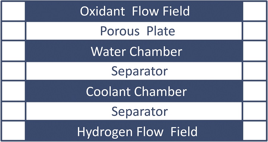
“That allowed us to implement a new design – a metallic, diffusion-bonded, monolithic BPP which contained the hydrogen and oxygen flow fields, coolant flow fields, product water flow fields and the phase separation membrane itself for separating the fuel cell product water from the oxygen gas, all in a very thin pore chamber assembly,” Smith explains.
“Initially we developed this for the NASA programme in 50 cm2 active area sizes, and then produced our BPPs and MEAs in 150 cm2 sizes, potentially for use in much larger and hence more powerful and power-dense fuel cells. NASA were happy with the performance of those cells and subsequently funded a range of short and tall cell stacks for testing.”
Such was NASA’s enthusiasm that it put Infinity in touch with the US Navy, who had a similar (albeit maritime) interest in air-independent power systems. That gradually led to research and solution development for the navy, such as that already being carried out for NASA but funded through the Office of Naval Research. Beginning in 2012, it continues to this day and is aimed at naval UUV applications.
“That continued development across different users enabled evolutionary changes to our engineering approach, allowing us to achieve higher differential pressures between the oxygen and by-product water,” Smith says.
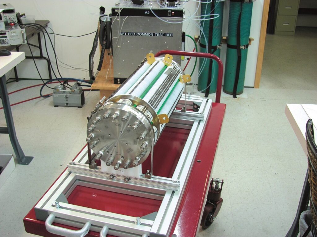
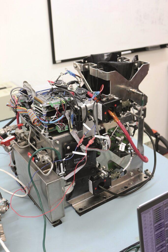
Most recently, fresh efforts by NASA to land on the Moon, and the growing private space industry, have brought another wave of funding to increase Infinity’s focus on orbital and lunar missions. This has included the flight of a NASA-funded, fully integrated Infinity PEMFC system, designated the Advanced Modular Power and Energy System, aboard the recent Blue Origin New Shepard-23 rocket flight. That mission was curtailed owing to an anomaly, but the fuel cell functioned successfully and produced valuable data.
“Now, with the stack’s technologies having been developed, matured and proven in a variety of test cases, we’re at a place where product deployment makes the most sense to us,” Smith comments.
Regenerative fuel cell
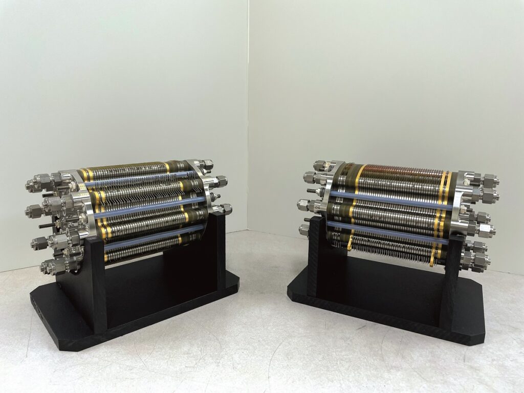
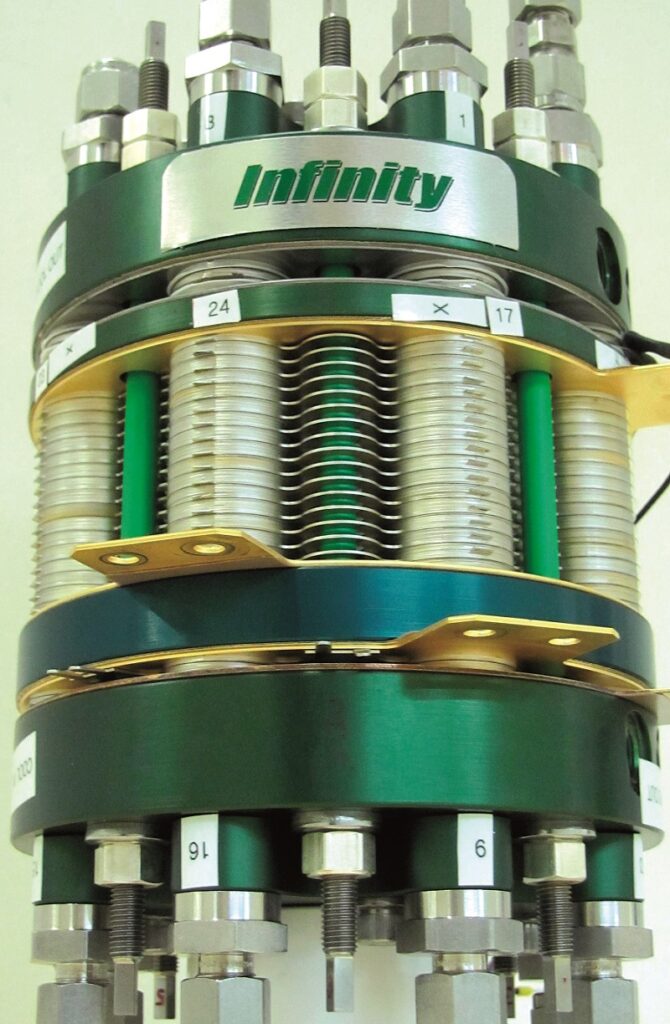
As mentioned, Infinity produces individual cells with active areas of 50 and 150 cm2, with Smith noting that his team also makes 300 cm2 cells, and can produce others. The cells are circular in shape, unlike the rectangular form taken by most PEMFCs we have previously covered, with a radius of just under 4 cm in the 50 cm2 cells, just under 7 cm for the 150 cm2 cells, and roughly 9 cm for the 300 cm2 cells.
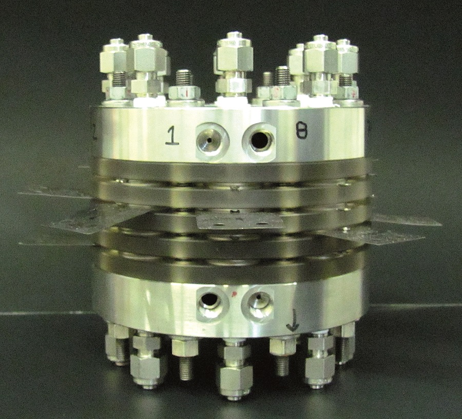
Naturally, the highly customised nature of Infinity’s solutions for space and subsea users makes it challenging to give exact figures on all the permutations of its PEMFCs, and certain aspects such as mounting points have not yet been standardised. However, Smith showed us a test unit that is the most likely to be productionised first.
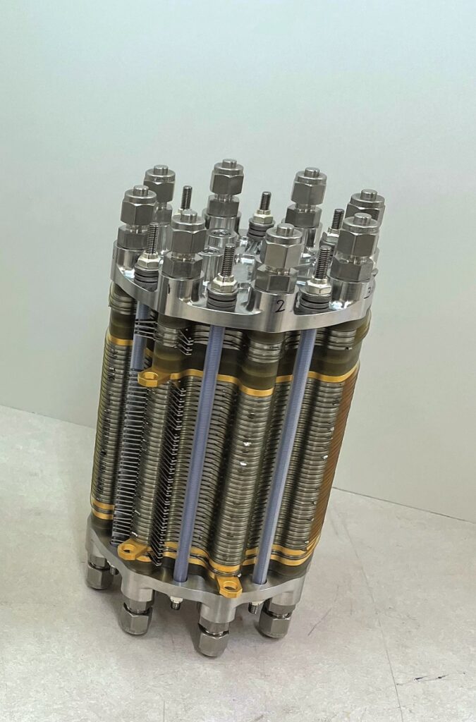
This is a stack with 36 layers of the 50 cm2 active area cells, roughly 25 cm long including the tie rods used to secure, tighten and pressurise the cells and BPPs; it is 10 cm in diameter and weighs just below 6 kg. As with all Infinity’s PEMFC solutions, it incorporates the APWR system as well as an inert concentrator and what are called active humidifier systems.
“It’s nominally designed for generating 500 W to 1 kW, and ideally for operating for extremely long missions as part of a regenerative fuel cell system,” Smith explains.
“If it’s installed in a lunar energy storage application, for example, combined with solar arrays, it can produce electricity and water at night when the arrays are not generating electricity, by running hydrogen and oxygen through the cell. This by-product [or just ‘product’] water can then be decomposed into hydrogen and oxygen during the lunar day in a separate electrolysis reaction using surplus electricity from the arrays.”
Using a similar diffusion-bonded technology, Infinity has also developed a separate family of high-pressure electrolysers that can produce hydrogen and oxygen as an energy storage medium at 2000 psi and above for later energy needs.
“That gives you an idea of how these solutions scale, particularly in terms of current density,” Smith says. “The number of cells sets the stack voltage, and of course the current multiplied by the voltage gives the power. With 36 cells and 0.8 V per cell, you get a PEMFC of about 28 V, and it could operate at a peak current of about 50 A at a slightly lower voltage per cell.”
He notes however that this does not tell the whole story: the mission profile, application and objectives have consistently been the primary dictators of each fuel cell’s design. “Sometimes you’re after very high power levels that you want for short periods of time; other times you’re after maximum efficiency, and the latter would drive the design in a very different direction to the former. There’s a lot of optimisation that impacts size, weight, power, cost and so on,” he says.
All-metal bonded cells
The materials in the cells’ MEAs are optimised to work with pure oxygen. This is most noticeable in the catalyst layer, as Smith notes that typical carbon-supported catalyst materials can be degraded through contact with pure oxygen gas.
“We therefore have a catalyst structure that’s compatible with pure oxygen, and is designed to be very hydrophobic so that it can remove the water effectively from the cathode side of the reaction,” he explains.
“And within the MEA layers, we use a fairly conventional Nafion material as our PEM layer, with a very high catalyst loading. That’s because although mission use cases vary, most of the time we’re after high performance and long life.
“In these applications, typically the amount of catalyst on the membrane does not have a major impact on cost as far as our users are concerned, so we ensure that it can not only withstand the corrosive pure oxygen environment but also the wetness of that environment, and still provide high, consistent power output over its lifetime.”
He adds that NASA would like that lifetime to be in the 10,000-20,000 hour range at least, longer if possible.
As mentioned, the BPPs are metallic, monolithic BPPs created through diffusion bonding. They serve to contain and pressurise the MEAs, as well as the various fluids flowing throughout the stack as reactants, coolants and waste products, and mount the pore chambers and phase separation membranes.
“We want to make our BPPs as lightweight as possible, but there are trade-offs,” Smith says. “In many of our applications, ruggedness and the ability to withstand shocks and vibrations are extremely important – imagine, say, a naval UUV working in mine countermeasures or a rocket being launched.

“We know many companies use graphite BPPs, but we also know from experience with other companies’ fuel cells that do use graphite plates that if you drop them on the floor, you end up with a lot of shards of graphite, whereas if you drop one of ours on the floor, you’re more likely to dent the floor. Metallic BPPs are ideal for handling shock and vibration, and if they are carefully designed and manufactured they can still be reasonably lightweight.”
Metallic BPPs cannot realistically be made solely through casting, and still feature the very fine and minute flow fields needed to allow precise delivery of hydrogen, oxygen, product water and unused reactant to their respective destinations. The flow fields are instead most often bonded onto the flat BPPs with adhesives such as epoxy resins, silicones or elastomers.
BPPs made this way can exhibit good levels of flatness and strength, but having these distinctly separate (albeit bonded) layers means they are prone to degradation through delamination over time, and can exhibit high resistance at the points of interface. Furthermore, the process is time-consuming and difficult to control.
Metal BPPs can also (as per Toyota’s approach) be mass-produced using stamping machinery, an approach that achieves very fine control and quality of parts, but the set-up costs of such a facility are really high. CNC-machining such plates is similarly costly to set up, and the integrity of the resulting BPPs can vary owing to how the metals are cut.
To overcome these various drawbacks and cost barriers, Infinity’s approach is to use a patented approach involving diffusion bonding. This is essentially a welding process in which multiple layers of metallic ‘foils’ are pressed together (most often in a vacuum chamber) at a specific pressure as well as a temperature of usually around 50-90% of the most fusible material’s melting point, with increases in the temperature aiding in the interdiffusion of the different atoms across the face of the joint.
The boundaries between the metal layers therefore disappear during the bonding process, ensuring high electrical conductivity and pressure integrity, as well as lower weight and greater ruggedness. This contributes to the survivability and power-to-weight ratio desired by most of Infinity’s naval, aerial and space users.

Diffusion bonding appeals to Infinity for other reasons. For instance, given that the process largely revolves around controlling the pressure, temperature and holding time across the areas of the materials being bonded, it can be largely automated. While current volumes are low, high-volume automated production might be possible to scale up manufacturing in the future.
“We also get a high degree of control over the design of each flow field, so we can get hydrogen and oxygen to exactly where we want them, for proper stoichiometry and efficiency across the active area of each MEA,” Smith says.
And for any Infinity PEMFCs using metallic porous membranes for the APWR process, the membrane can be directly diffusion bonded into the BPP assembly, further simplifying the production process. Alternatively, if polymer-based membranes are chosen (to reduce weight), the membrane must be incorporated into the cell separately.
“It’s difficult to overstate how robust and rugged the plates resulting from diffusion bonding are,” Smith notes. “And I think the industry is finding stainless steel plates becoming more common, even in fuel cells using ambient air, because it’s a much less expensive and more effective material than alternatives for BPPs.”
He adds that the BPPs also have a protective coating layer, which as well as enhancing their ruggedness adds conductivity, minimising the interfacial contact resistance and hence current losses throughout the stack – mitigating a common issue with PEMFCs.
“Also, the way we diffusion-bond these BPPs, we’re essentially making four different chambers in each one – a product water chamber, an oxygen chamber, a hydrogen chamber and a coolant chamber – and they all become perfectly joined together as one piece of metal, with basically no interfacial contact resistance between each of the layers.”
Operation
The fuel cell’s optimal performance, in terms of energy efficiency and health, is achieved when the internal environment is maintained at a nominal temperature of around 70 ºC. However, the company has also found through testing that the fuel cell can continue operating smoothly when its internal temperature is anywhere from just over 0 ºC to just below 100 ºC, albeit with some loss of performance at those extremes.
The start-up time and configuration of the cell can vary according to the application. In the Blue Origin New Shepard-23 flight for example, it was designed for remote activation, with its operation being automated.
“After commencing the remote start, the system pressurised itself internally to its target pressure, before introducing reactants from the external hydrogen and oxygen storage units,” says Smith.
“Then it went through a series of self-checks, making sure all the electronics and valves were working correctly, and finally introduced the initial load. That whole process took between 1 and 2 minutes, and that was after it had been switched off and in storage for an extended period without operational checks.”
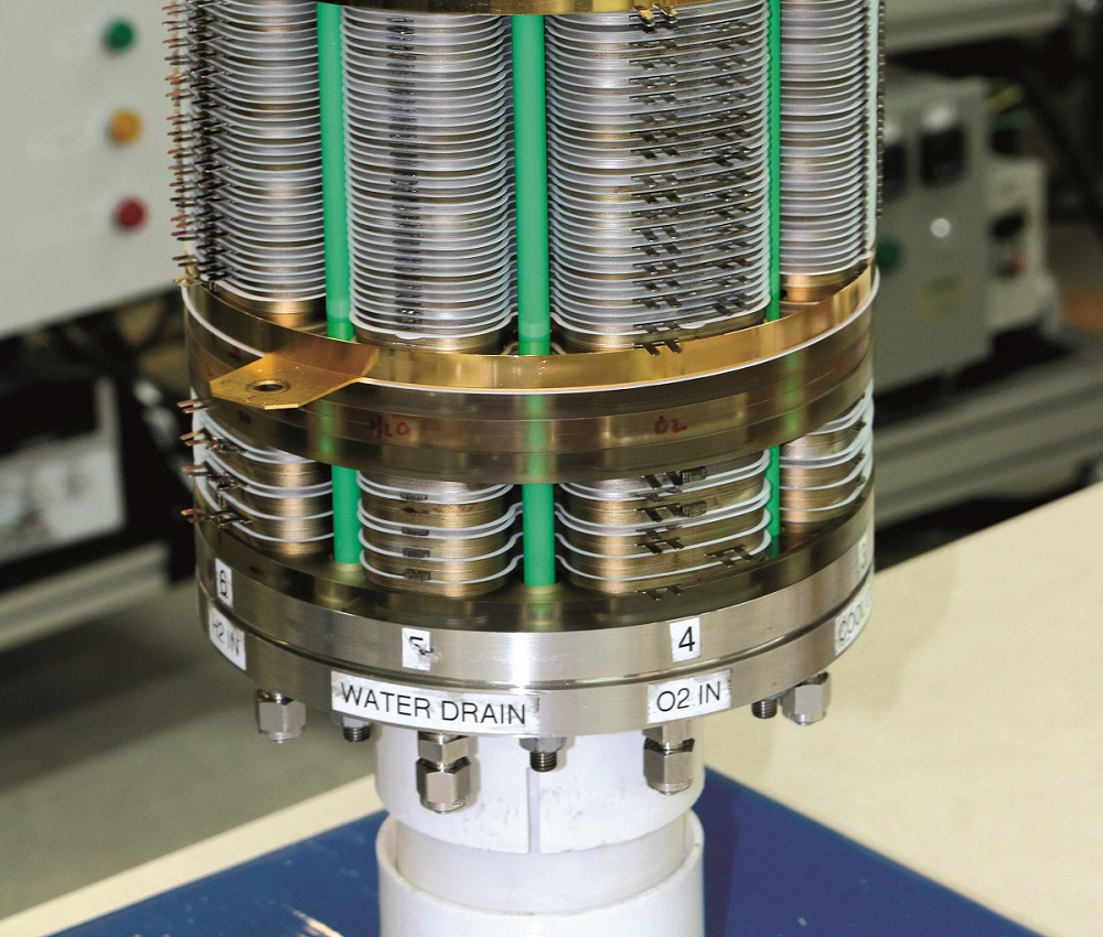
After start-up, the pressure regulators allow the hydrogen and oxygen reactant gases through to the fuel cell, which enter through one of the circular end plates and flow into their respective chambers within each BPP-MEA grouping via manifolds in the stack. The opposite end plate meanwhile vents the water collected via the APWR system, as well as any inert gases.

Balance of plant
Most often, Infinity uses mechanical pressure regulators to reduce the highly pressurised hydrogen and oxygen to levels ideal for the internal chambers in the stack, most often going from 100-150 psia down to 45 psia, although it has used and can install electronic regulators depending on the application.
“For instance, a wide dynamic range in the fuel cell might result in single-point mechanical regulators suffering significant droop when going from low power to high power,” Smith notes. “At that point it might be useful to have either multiple mechanical regulators or just electronic regulation to accommodate that change in demand and prevent the droop.”
Although high-purity hydrogen and oxygen are used, Smith says that since Infinity’s fuel cell is a dead-ended design, any inert gases that enter with the reactant gases will accumulate and must be vented.
“We have a way of concentrating the inert gases inside the stack, so that when we do vent, we’re minimising the amount of unused reactant gas that exits the stack,” he adds. “It’s a proprietary design that allows us to flow hydrogen and oxygen through the stack in a way that concentrates those gases down to one end of the stack, in a device we call the inert concentrator cell section.
“That captures and circulates gas at one end of the stack, and when it reaches a level that we measure by passing a current or voltage through that individual cell, we vent that very small portion of the stack. That means we don’t have to vent the whole stack at once, which would be wasteful, and we get extremely high usage rates of the reactants.”
Also, since PEMFC life is directly affected by humidifying the reactants, Infinity also provides an in-stack means of humidifying the hydrogen and oxygen while also reducing or eliminating any gas in the product water.
At the opposite end of the stack from the vents is a series of cells that expose the incoming hydrogen and oxygen to the product water before it exits the stack, humidifying the gases. That section also includes an electrochemical means of reacting dissolved or visible reactants that might be present in the product water, minimising downstream water management, particularly for zero-gravity applications.
External balance of plant
The exact arrangement of mechanical and electronic parts comprising the external BoP is not standardised in design terms. For instance, in the recent Blue Origin flight, most of those components were mounted directly on the fuel cell’s end plates to eliminate the need for external piping.
“Putting everything, including the valves and pressure regulators, right on the end plates made everything smaller and lighter, and kept overall packaging really tight, which is really important for any kind of spacecraft,” Smith says.
“Earlier in development, we would just use thick pieces of stainless steel for our end plates, because that was low-risk and we didn’t want to have to design too much new technology into an end plate. But what we’ve evolved towards now are end plates that sometimes actually contain the BoP – so the BoP is integrated not just onto but inside the end plate.”
The productionised PEMFCs will probably therefore use end plates with fluid ports running through them, to allow pressure regulators and valves to function. Infinity is also considering alternatives to stainless steel for manufacturing its end plates, such as carbon composite for further weight reduction when the application calls for it, for instance in air or space flight.
As a final note about the end plates, Smith notes that the tie rods used for tightening the stack are likely to remain in all future iterations, as they provide ideal control and repeatability over the compression across the cell, particularly compared with alternative approaches such as straps.
“We’ve used stainless steel and titanium tie rods, and both work well and are very safe,” he adds.
Thermal management and system control
Infinity designs, develops, manufactures and programs its own embedded electronic control units for managing the cell stack and BoP, principally for monitoring each fuel cell for health conditions, intermittently venting inerts and water, and communicating health and performance information to external data buses.
Each controller is designed for a mission’s required signal counts, data acquisition rates, memory rates and so on. The embedded software meanwhile implements Infinity’s algorithms for controlling the BoP and electrical output, achieving stable data storage and communicating operational parameters.
Each version of the software is also validated and verified to the industry standards appropriate to the application, spaceflight standards being the most rigorous.
The controller is typically mounted with the rest of the BoP – that is, the regulators and valves, as well as product water storage and potentially the thermal storage systems, depending on the application.

“In some missions, such as the New Shepard-23, we were not allowed to increase the thermal load inside the pressurised capsule. Other missions, such as flight or lunar surface missions, are equally challenging,” Smith says. “With space being a vacuum, cooling is really difficult, as there’s nowhere for heat to go by conventional means.
“To meet the New Shepard-23 requirement we needed to implement a thermal storage system. To do this we used a heat exchanger embedded in a wax-like phase change material [PCM], which absorbed the heat we created in the mission. The New Shepard-23 had a finite mission duration, so a PCM system could be defined.
“Usually though, a fuel cell operating for an extended period needs to have a clear heat rejection pathway. For example, you can circulate water or some other fluid through the stack and route the water to that rejection spot, or for a UUV you have the sea around you as a great heat sink. So that New Shepard-23 PCM system was a very mission-specific creation.”
As Infinity’s fuel cells are air-independent, it follows that they are closed-cathode systems, where the oxygen intake channel is not used for air-cooling. As mentioned, the four-chamber design includes a coolant chamber, through which liquid coolant (typically but not exclusively water) is circulated for every BPP, to achieve quick distribution and balancing of cooling across the stack, including in the humidifier section.
“We reject the heat through that coolant loop to an external source. It can be another circulation loop, meaning a liquid-to-liquid heat exchange system, or we can use a cold plate in UUV as well as some space applications,” Smith says.
Future plans
As discussed, Infinity Fuel Cell and Hydrogen is now transitioning from prototyping and customising bespoke solutions towards a catalogue of productionised power system products for customers seeking scale orders.
“We expect to have our beta-testing production units ready for interested parties to trial by the end of 2023, and then wide commercial availability in 2024,” Smith says.
“Overall, we anticipate that the products will be extremely similar in architecture to what we’ve talked about here. However, as we collect new data from missions across space, sea and air, we’ll find ways to further optimise weight, ruggedness and performance, so we’ll have families of fuel cells suited to what individual users need in terms of form factors, currents, voltages, costs and so on.”
Advanced Product Water Removal
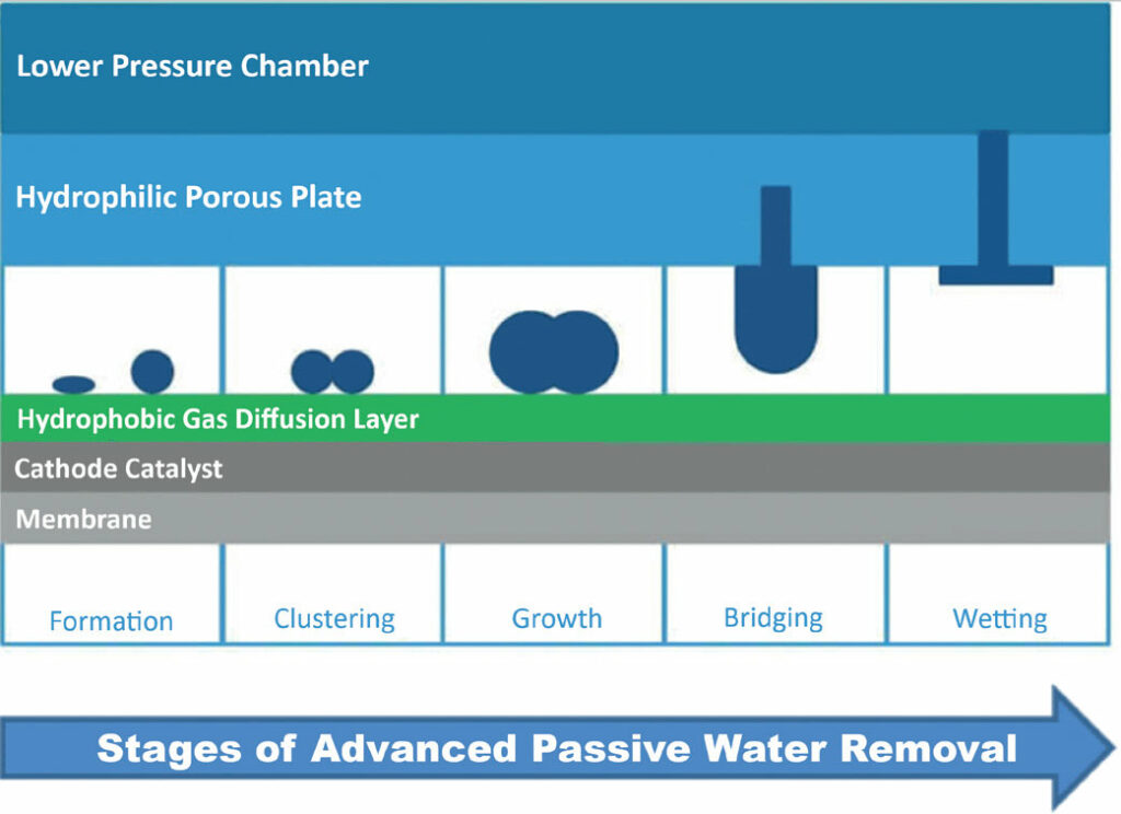
Each active, current-producing cell in a PEMFC stack is otherwise known as a membrane electrode assembly (MEA). The number of layers in the MEA will differ according to the design, but generally include a single proton exchange membrane at the core, sandwiched by two catalyst layers and then two gas diffusion layers (GDLs) on the outermost sides.
As water is produced at the site of the electrochemical reaction, it exudes outwards from the catalyst layer on the cathode side of the fuel cell (where the oxygen reactant is input), and then out from the gas diffusion layer.

A sequence of components are key to the stages by which this waste water is passively removed and hence flooding of the stack is prevented.
First, the GDL material is hydrophobic, so it repels the water, causing it to form as droplets on the GDL’s outer surface. Next, between each GDL and bipolar plate in the stack sits a screen material layer, a porous membrane and a water cavity. The membrane’s porous material can be metallic or a polymer, depending on factors such as weight, cost and availability.
“The water then moves through the screen layer, which can be around 304.8 microns thick. The droplets build up through that screen material and touch the porous membrane on the other side,” says William Smith, Infinity’s president and founder.
“Whether the porous membrane is a metal or a polymer, water will pass through its pores because they’re fine enough to conduct water easily, but they will resist intrusion of any gases owing to surface tension effects caused by van der Waals forces, up to differential pressures of 50 psi.
“That resistance is maintained passively through the constant pressure level in the water cavity on the other side of that membrane, which is lower than that of the pressure in the MEA’s oxygen chamber. The differential pressure can be as low as 2-3 psid, but a higher differential pressure can simplify the overall control system design.
“That results in a highly effective water-gas phase separator, and we incorporate this arrangement of screen material, porous membrane and water removal cavity in every layer of our fuel cell stack. Except for the pressure control, no other active control system is needed at the core of this water removal process.”
The electrochemical reaction’s by-product water is therefore removed from the PEMFC stack’s cells without using any moving parts, and the hydrophobic GDL and pressure differential ensure that neither gravity nor its absence impact the process. The water cavities are joined using a manifold, through which the water can flow directly from the stack into an external water collection system.
Notably, the passive water removal technology in the Gemini spacecraft (see main article) used a similar configuration, but with the porous material also installed outside the fuel cell stack. That stack was inside a pressurised oxygen chamber, making for a far more bulky and complicated system than Infinity’s turnkey approach.
- Specifications
Infinity base fuel cell
PEMFC
- Length: 25 cm
- Diameter: 10 cm
- Weight: less than 6 kg
- Active fuel cell area: 50 cm2
- Number of fuel cell layers: 36
- Nominal voltage: 28 V DC
- Maximum current output: 50 A
- Maximum power output: 1 kW
UPCOMING EVENTS


