


ULPower UL350i and UL350iHPS
From race crew to no crew
Moving from rally cars to uncrewed systems has led to this company producing a range of aero engines, the best-selling of which Rory Jackson investigates here
(Images courtesy of ULPower)
ULPower Aero Engines is a Belgian company best known for designing and supplying power units for a variety of light sport aircraft. Its inception can be traced back to 2001, when CEO Patrick Denorme and his engineers – who had been making rally cars – were first approached by a company requesting help with tuning an engine for a helicopter project.
After that company stopped the project, Denorme and his team decided to restart it from scratch. They then updated the design and its features with more modern subsystems (for 2001’s aviation engines) such as EFI, direct propeller and generator drive, and management by ECU.
The team’s experience with rally cars taught them to avoid overly complex designs and any parts that would be costly or difficult to replace, while still seeking to push the performance of their engines as far as possible. In 2006, when Denorme was satisfied with the fruits of their r&d, ULPower was officially founded as a company and its first UAV engine, the UL260, was introduced.
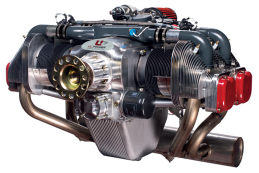
While ULPower now produces a number of engines, the UL350 is its best-seller in the UAV world, hence our focus on it here. The standard-issue UL350, styled the UL350i, is a four-stroke, spark-ignited gasoline engine that weighs 78.4 kg when fully built with all ancillaries. It is a flat-four boxer engine that displaces 3503 cc (from which it takes its name) and produces 118 bhp (86.8 kW) of peak power.
In addition to investigating the UL350i, we will also investigate a novel forced-air cooling system featured on the company’s UL350iHPS (High Power System), a version intended particularly for rotor-wing applications where no oncoming rush of airflow is typically available to help cool the engine. In addition to aiding safe operations on helicopter and multi-rotor aircraft, the UL350iHPS produces up to 150 bhp thanks to a modified camshaft and manifold.
Overview and philosophy
The UL series has four key members, with variants within each one. In addition to the UL350, they are the UL260, the UL390 and the UL520, with their names corresponding approximately to their capacities, like the UL350.
All the engines follow a very similar design style and engineering philosophy, not least in being flat-opposed four-stroke spark-ignited types, and while the UL260 is a four-cylinder the UL390 and UL520 are six-cylinder systems.
Crankcases, cylinder heads, combustion chambers, crankshafts and other core parts are recognisable from one model to the next, with common specs such as a 105.6 mm bore and a peak crankshaft speed of around 3300-3500 rpm.
Also, common operational features include electronic spark ignition for variable timing, electronic multipoint fuel injection for pressure and temperature compensation, and the possibility of integrating the forced-air cooling system for more power.
As mentioned, ULPower’s first engine was the roughly 72 kg, 97 bhp UL260, completed and commercialised in 2006. New variations of this design across the displacement classes of the UL series have been regularly unveiled since then to serve customer requests such as for higher power and acrobatic flying.
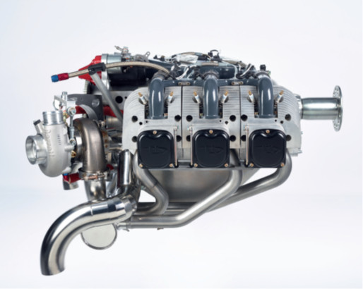
Its latest engine, the UL520T, was unveiled in 2021. This is a version of the UL520i featuring a custom turbocharger for improved power and high-altitude operations, weighing 108 kg when equipped with all the typical accessories and outputting up to 200-220 bhp depending on the exact configuration. ULPower comments that the UL520T could therefore also be ideal for the burgeoning generation of very large, heavy-lift UAVs for air freight operations.

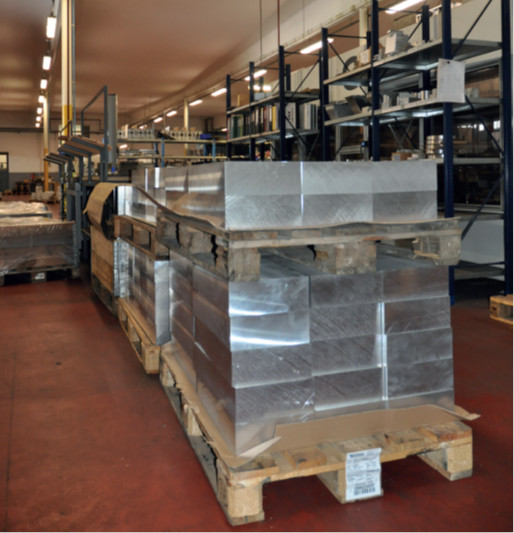
The UL350i itself was launched in 2009, with the UL350iHPS following in 2010. Around 80% of ULPower’s engine parts are produced in-house, with the company’s five-axis CNC milling machine and automated production lines for instance being key assets for cutting aluminium and other metals; steel parts are made by Ropa, one of ULPower’s shareholders. A few remaining treatments and parts come from some subcontractors in Belgium and the US.
“Most parts in the engine are cut from billet,” Denorme says. “When we started 15 years ago, we sought to cast everything, but we wanted to get rid of the porosities we were getting in the cast parts because it led to too many weaknesses.
“With high-quality billets we basically never get porosities. And as a side benefit, whenever we want to make or test modified engine parts – which is often – we don’t have to expend time or money on changing casting moulds; we just change the CNC machine’s programming. It’s so much quicker and easier that way.”
Jakob Defoer, quality engineer at ULPower, says, “We also have extensive test benches, as practical experimenting and real-world results are much more central to our r&d than computer-based calculations and simulations. Having a five-axis milling machine means we can iterate new parts really quickly to test some new design idea or a customer’s request, then assemble it and throw it on the dynamometer to see what it turns up.
“For the turbocharged UL520T for instance, we started with a basic turbocharger simulation, then did our calculations for the air densities the customer wanted to fly at. We then quickly went to testing in order to optimise the wastegate and adapt the mappings in the ECU, followed by some failure mode and effect analyses to make the system as safe as possible, before programming the safety modes into the ECU and going to test flights.
“That’s a very component-specific example, but it’s representative of our overall engine development philosophy, and how differently we can modify each of our designs for different customers and operating environments. As a further example, the manifolds are fairly different for the UL520T versus our other engines: a naturally aspirated engine sucks air in, whereas a turbocharged engine has its air pushed in, so some very different fluid dynamics had to be accounted for when we developed the airbox for that system.”
Starting and electric power
The standard UL350 comes with a 1.2 kW starter. “It’s a Bendix-type generator with built-in solenoids,” Defoer says. “It has two connectors with some quite big AWG 4 cables, so the battery must be able to handle that, especially if the user wants to have enough current for cold-crank starting.
“Also, the starter’s ring gear is bolted directly onto the crankshaft for direct drive, so the pilot or autopilot can start the engine right away without belts or chains to worry about. Once the ECU detects some rpm, it responds by starting to inject the fuel quantities for standard fuel-air mixtures, and the engine starts running.”
The UL350 comes with a standard generator of 30 A, or a 50 A generator can be installed if preferred. For UAVs running one or more sensor payloads, GPUs, comms relay antennas or other electronics that require high power, an external alternator of up to 4.2 kW can be integrated.
Throttle and fuel
The throttle body and lever are laser-cut from aluminium before being welded together to precise tolerances in order to meet the airflow and weight targets.
“Naturally it’s critical to our engines’ performance targets that we can always bring in the right quantity of air, so for our four-cylinder engines we use a 38 mm throttle, while on the six-cylinders we go with a 45 mm throttle,” Defoer says.
“It’s a single-lever throttle, as that makes it very simple to control. Until 2 years ago we used a potentiometer for throttle position sensing on the four-cylinder engines, but we have since switched to a Hall effect sensor. It’s brushless and hence suffers much less wear than the potentiometer, making it more reliable and long-lasting.” Also, the dual-exit design of the Hall sensor makes for straightforward integration of two ECUs if the end-user wants a dual-redundant engine management system.
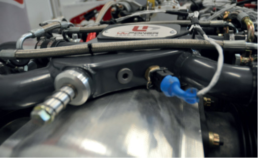
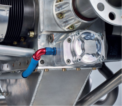
Downstream from the throttle is the air manifold. ULPower casts its manifolds for the UL350 from aluminium for structural strength, before milling the cast parts down to thinner, tighter tolerances (which is critical for saving weight) before welding them together to a base plate that sits at the bottom. The designs have been optimised to ensure an even balance of airflow to all four cylinders.
Upstream from the throttle is the air filter, which tends to be mounted and located in a way that helps maintain a safe internal temperature in the airbox.
“The UL260 and UL350 actually use the same airbox, but we add some aluminium extension tubes to the UL350’s manifolds to compensate for the extra 8 cm of cylinder stroke of the latter,” Defoer says.
For fuel spray, the engines are designed with multi-point injection rather than a single-point injector behind the throttle. Injector holders are installed atop the air manifolds running into the cylinder heads, which are fixed to the injectors to spray at angles of 45º into the inlet tubes, mixing with the air as it flows from airbox to valve.
“Also, the ECU pulses all four injectors at once, rather than timing each spray for each cylinder at individual, specific crank angles,” adds Defoer. “That’s the simplest way to do it from a programming perspective, and our tests and customer reports indicate that it works just fine, and that there’s no significant performance or efficiency gain to be had from going with a more computationally complex timing approach.”
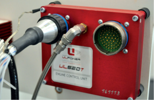
Engine management
Keeping ECU development in-house is critical for the company, as it allows for constant adjustments and improvements to its programming. Also, all the fuel-air mapping is managed electronically in real time using maps embedded in the onboard data storage.
“Every new prototype engine runs on the test bench for weeks, sometimes months. During that time we’ll change injection quantities, ignition timings, throttle widths and more, to observe how the engine performs at all points across its envelope and to determine how we can maximise safety, fuel economy and so on,” Denorme says.
The ECU controls the engine’s timing and fuel-air mixture from start-up to shut down. As a result, the cockpit of any crewed aircraft running on a ULPower engine has only a single lever – the throttle.
The management system is designed as a full authority digital engine control (FADEC) module, which was developed from a blank sheet originally for managing rally car engines before being redesigned for aviation by an unnamed partner with experience in inferring differences in engine management approaches between vehicle types.
“The FADEC system automatically sets the fuel mixture and ignition timing multiple times per second,” Denorme explains. “It will even fine-tune the fuel flow to compensate for changes in barometric pressure as well as inlet air temperature in the inlet manifold. That brings a tangible bonus in terms of cold and hot starts.”
To carry out these functions effectively, the ECU is embedded with a 3D fuel map containing the mixture and timing control orders for operating at up to 18,000 ft, including timing corrections to prevent detonations, and a built-in rev limiter set to 3300 rpm on most ULPower engines for safety and fuel efficiency.
The mapping is based on data received from five sensors. The first is the sensor for crankshaft position and speed, data from which enables the ECU to infer the position and speed of each cylinder’s piston and valves. That then allows the ECU to calculate when to trigger the spark plugs, and when to advance or retard the ignition timing.
Next is the throttle position sensor (TPS). Throttle position data allows the ECU to infer and track the power and acceleration rates that the engine is running at any given moment. As a rule, TPS and crank rpm data are two of the most important inputs, as they form the x and y axes of the ECU’s fuel map.
Meanwhile, the oil temperature sensor provides an insight into whether the engine is starting hot or cold, so that the ECU knows how lean or rich the charge should be to ensure easy starting and smooth running.
Lastly, the sensors for manifold air temperature and air pressure supply the data inputs for calculating ambient air density, which is then used to further inform the correct amount of fuel to use.
“If one of these sensors fails or becomes disconnected, the engine will continue to run but not as efficiently as it would be using ‘default values’ in place of the real ones,” Defoer says. “The only sensor that is critical to continued operation of any ECU controlled engine is the crankshaft position sensor.”
Cranktrain
Being a flat-four design, the UL350 can run using a flat-plane crankshaft, with its crank throws and pins disposed such that the first and fourth pins sit at 180º to the second and third.
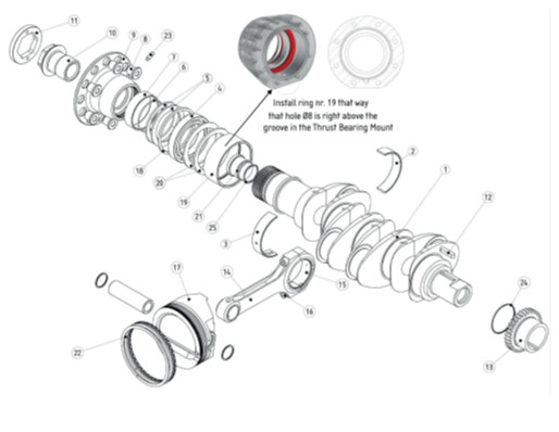
That makes for a simple design and construction with minimal counterweighting. The company cuts the crankshaft from a single piece of steel alloy (hence the con rods are split at their big ends), including drilling of oil channels for the con rods, with final balancing tests or modifications performed on each shaft before it goes for assembly.
“We’ve also done special frequency tests to test the crankshaft’s torsional and bending characteristics,” says Defoer. “We put a laser vibrometer onto the engine and ran it across its operating range to see if there were any vibrations or harmonics at key points, and found we’re well below the practical limits for all regulations and mission types, so we don’t need any damping systems or similar.”
A total of five split bushings (or plain bearings) hold the crankshaft in place. “We also have an extra ball bearing on the top of the shaft to pick up the axial forces acting on it,” Denorme says.
“That’s important, because when you’re flying an aircraft, compared with an automotive engine the propeller can impart some serious axial pulling or pushing forces on the crankshaft. So we’ll put one ball bearing on our four-cylinder engines and two in our six-cylinders to keep the shaft exactly in position. That means our engines can be used in pusher or traction propeller configurations in UAVs.”
He adds that as well as the crankshaft being nitrided for hardness and its pins polished for smooth motion, the bushings holding the shaft come with an automotive-type coating, to avoid the need to apply it to the shaft or its seats.
“Like the crankshaft, the con rods are somewhat overdesigned,” Denorme says. “The 4140 steel alloy gives great toughness and tensile strength, and it can be hardened very easily.
“The con rods mount on the crank pins using split bushings, and each one attaches onto the piston pin using a brass bushing. The piston pin is made from an undisclosed hard material, so we go with the brass to have the pin move against something soft.
“That, and the nature of brass, make for very good lubrication without needing special coatings. It’s a well-proven approach in automotive engines, and the piston pin is similarly a well-proven type used in automotive engines, which we get delivered with the con rods.
“After taking delivery of the con rods we also check their weight to ensure they’re no more than 5 g apart. If any of them are, we’ll set them either side of the crankshaft before performing a final full weight test so they balance out.”
Combustion
The cylinders fire in the order 1-3-2-4, a sequence used in all four-cylinder ULPower engines to minimise vibration. Ignition is performed using automotive-type coils for reliability, with the FADEC wired directly to the spark plugs for supplying power and control signals, in addition to calculating the variable spark timing that is key to the engine’s effective ignition advances. Two spark plugs sit in each cylinder for redundancy, and fire at the same time.

Once the fuel-air mixture passes through the cylinder head, via a system of overhead poppet valves, they enter a ‘squish’ zone designed into the combustion chamber that narrows to a gap of less than 1 mm between the piston and the cylinder head at the former’s TDC. The turbulence created by this, and the shape of the piston crown and cylinder head, is aimed at causing as homogeneous a fuel-air mixture as possible, to minimise the risk of detonation.
“We’re fortunate that our partners in Ostend have a lot of experience in rally car engines – it’s their expertise that informs key design targets for the cylinder interior,” Denorme explains. “For instance, the shape formed between the piston crown and cylinder head must always push the charge mixture specifically towards the spark plugs, so we try to keep the spark plug right in the middle and we cut and forge the two sides into a ball-like shape for the detonation.
“Getting it perfect wasn’t easy, as we needed to compromise on how spherical the shape is in some sections of the chamber, to be able to fit two spark plugs and two poppet valves inside. But we’re very satisfied with the very tight compression that the piston imparts on the gases against the plugs now.”
The exhaust gases also exit through a poppet valve. The exhaust system sitting downstream is kept particularly simple, using COTS parts most of the time. Either a four-into-one exhaust pipe system or a muffler can be installed, depending on customer preference.
The company notes that different exhaust systems are available. Since the fuel maps are modified to match the exhaust system, it is important that customers decide which exhaust system is best suited for their aircraft.
“A four-into-one will get maybe 2 bhp more out of the engine than a muffler,” Defoer comments. “Granted, that isn’t much, but many customers will want it in order to squeeze every last bit of energy out of the combustion chambers, be it for payload carrying, data processing, AI functions or manoeuvres.
“Of course though, there are lots of different kinds of UAV designs, so some customers will prefer separate exhaust pipes on the left and right for integration purposes, or mufflers for noise and vibration benefits.

“Naturally we can run tests in-house if a customer wants a special exhaust or has an idea for an exhaust manifold or muffler that hasn’t been paired with our engines before. We’ll install Lambda sensors on the exhaust system to test if the power and air-fuel levels are running the same, then adjust the fuel-air maps if necessary.”
Valvetrain
As mentioned, overhead poppet valves are used for the intake and exhaust, with one valve for each – hence two valves total – per cylinder being sufficient for the relatively low rpm (compared with most other gasoline engines we have featured) that the UL350 runs at.
“If we were building higher speed gasoline engines that ran upwards of 6000 rpm, we’d switch to four valves per cylinder: two for the charge intake and two for the exhaust,” Defoer says. “For now though, two valves per cylinder is enough, and they sit at about 15º offset from the stroke. The intake valve is about 40 mm in diameter and the exhaust is around 32 mm.”
The valvetrain starts with a single camshaft, which is gear-driven by the crankshaft at half the latter’s speed.
Denorme comments that the camshaft mounts in a chamber below the crankshaft, the crankshaft runs in the crankcase’s aluminium chamber and is held in place by five plain bearings that are directly greased via channels running from the main oil gallery.
It features eight cam lobes, as well as a driven gear fastened onto the back, with a standard sequence of valvetrain parts leading down to the cylinder heads. First, a cam pushes on a cam follower, which sits atop a pushrod that acts on one end of a rocker by way of a tappet adjustment screw. The opposite rocker arm pushes down on a valve stem to open the valve, each valve being held in a spring that in turn is held in place by retainers top and bottom, to help with the consistency of valve timing and force.
“Every part engaged or actuated in the valvetrain is made from 4140 chrome molybdenum steel alloy – in fact, so are the crankshaft and con rods, for the strength that alloy gives,” Defoer says.
“The tips of the valves are given a hardening treatment to last longer against the friction of the rocker arms, and for similar anti-wear reasons the cam followers have a special proprietary coating that we adopted after taking inspiration from some Formula One engines.”
ULPower also includes a proprietary design feature in the cams themselves. Although the exact nature of the feature cannot be disclosed, it reduces the wear experienced by each cam follower over time, again helping them and their coatings last longer.
“Also, the cams all have 114º of lobe separation, except in the UL350iHPS, which has 110º,” Defoer says.
Forced cooling
The cooling system is contained in a box-like shroud that sits around much of the engine. It weighs 12 kg on ULPower’s four-cylinder engines and 15 kg on its six-cylinders.
The system consists of an aluminium impeller fan that is directly driven by the crankshaft. The fan sucks 1 m3 of air per second into an airbox for distribution to the cylinder heads at 3000 rpm. Defoer adds that the fan takes only about 1 hp to move. The eight-blade rotor-impeller is milled in-house before being mounted onto the crankshaft by way of a fixed coupling sub-assembly.
Two ram airboxes extend backwards from the rotor housing surrounding the fan – one sits over the left cylinder heads and the other over the right ones. The internal airflow dynamics have been designed to ensure an equal distribution of air to every cylinder and head, and hence an equal performance boost from the extra cooling.
“The shroud was originally made from composite, but for reasons of easy mounting as well as maintenance of the engine, we switched to making it all-metal,” Denorme says.
“The size of the cooling system is such that a manufacturer wishing to take advantage of the UL350iHPS would be better off designing and building an all-new aircraft around the engine, rather than trying to use the UL350iHPS as a drop-in replacement for the UL350i.”
It is important to note that the cooling system does not rely solely on air for heat exchange. It also contains an integrated oil cooler that sits beneath the fan, acting such that the lubrication also provides cooling throughout the inner engine. While the oil is usually cooled by the air rush during flight, this approach guarantees that the oil temperature never rises above 120 C, to ensure effective cooling.
Oil system
Oil is stored in a cast aluminium sump, although larger sumps welded from aluminium can also be supplied. These were standard issue in previous iterations of the engines, and are still used by some aerobatics customers.
“We bolt a wet sump at the bottom of the engine, so oil drain or return happens naturally through gravity,” Defoer says.
“Oil drawn from the sump first passes through a coarse filter before passing through our pump – and we install quite a big pump to generate enough oil pressure and flow rate to extract heat from the engine. It’s a 25 mm-thick rotor inside the pump on the UL350, while on our six-cylinder engines the oil pumps contain two 20 mm rotors.
“The oil pump is fixed to the crankcase, and directly driven via a shaft that mounts using a split connection on the front of the camshaft,” he adds. “The fuel pumps, on the other hand, are electromechanical devices from Bosch, and are widely used in FADEC engines.”
After passing through the pump, the oil typically runs through the oil cooler. However, to avoid long warm-up times a thermostat checks the oil temperature, and if it is below 80 C, the thermostat switches two valves to send the oil on through a channel that bypasses the cooler.
The oil then runs through a fine filter before passing into the main oil gallery that sits on the engine’s left side. Near here is an empty port where end-users can install or have customised another oil sensor if they wish.
“From the main gallery the oil is delivered to the cylinder head,” Defoer says. “Every cylinder head has its own oil supply line, which is held in place by banjo bolts, with each line running from the oil gallery to the top of the head.
“The oil enters the head and is sprayed onto the tops of the rocker tappets and valve stamps to lubricate and cool those parts directly. The oil then drains into the tubes where the pushrods are located, so from there it lubricates the cam followers, before draining back into the sump.
“There are other channels that directly lubricate the camshaft, crankshaft bearings and con rods – the crankshaft is drilled with holes for routing oil directly to the con rods. And even indirect lubrication and cooling is generated through the ambient fog of oil inside the crankcase, so there’s never a lack of oil anywhere, and it is all eventually recovered by wafting back down to the sump.”
Future plans
ULPower’s engineers are particularly interested in ways to make their engines greener. To that end, the company is working with several customers on new configurations of its engines. Some of these are fully hybridised versions with alternators that can convert around 90% or more of its shaft horsepower into electricity, and plans are also moving forward on versions with seals and combustion chambers redesigned to run on alternative fuels such as hydrogen.
“Later this year we’ll start a theoretical study with one of our university partners into what kinds of alternative and sustainable aviation fuels could be viable for our customers to use,” Defoer says. “Based on our findings there, we’ll start putting some of our spare engines on test benches, running them on the sustainable fuel types and adapting our fuel maps to see what they yield in terms of running costs, safety, lifetime and so on.
“Then, wherever necessary, we’ll cut new metal to optimise how the engine runs on those fuels, so that when the time comes we’ll be able to offer the UAV market something sustainable, reliable and efficient.”
Anatomy
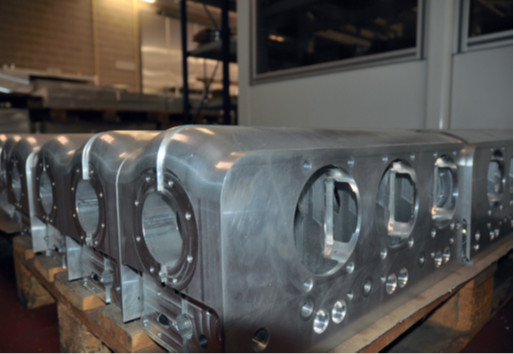
The UL350i’s crankcase is 6082 aluminium, cut from billet as two halves that split vertically down the middle, lengthwise with the crankshaft, and held together by 10 studs.
The cylinders are 42CrMo4V steel, and notably (for UAV spark-ignited engines) they are linerless and use no coating, as the engine’s relatively slow speeds make it unnecessary to do so.
Like the crankcase, the cylinder heads are cut from 6082 aluminium, as it is ideal not only for machining but also providing the necessary strength for the combustion chambers.
The cylinders join to the crankcase using Viton gaskets, while a proprietary material gasket sits between each cylinder and head. Each head bolts to each cylinder using six M8x1x35 screws of 12.9 steel. The company has also sought to maximise the size of the cooling fins cut around each head, and has found that, as far as power-to-weight efficiency is concerned, “the larger the better”.

The crankshaft, camshaft and con rods are made from high-strength 4140 steel alloy; these parts are also nitride for added hardness. They are each milled from a single billet, with forging as a potential option for the crankshaft if production quantities justify investing in forging tools. The crank is located within five plain bearings and a single ball bearing for thrust.
As the crankshaft is monolithic, each con rod splits at its big end, with the two pieces held together again by two M8x1x35 bolts made from 12.9 steel. The pistons are forged from aluminium and stamped into shape for minimised porosity and exact combustion chamber geometry. Three piston rings are mounted, with the bottom one acting as an oil scraper and support rings above and below it.
Specifications
UL350i/UL350iHPS
Four-stroke
Opposed four-cylinder
Gasoline (Mogas minimum 95 octane on UL350i, minimum 98 octane on the UL350iS or UL350iHPS)
Spark ignition
Naturally aspirated
Air-cooled (forced-air cooling on the UL350iHPS)
Displacement: 3503 cc
Bore and stroke: 105.6 x 100 mm
Weight: 78.4 kg (90.4 kg on the UL350iHPS)
Maximum power output: 88.2 kW at 3300 rpm (106 kW at 3500 rpm on the UL350iHPS)
DC output: 30 or 50 A
Compression ratio: 8:1 (8.7:1 on the UL350iHPS and other UL350 engines)
TBO: 1500 hours
UPCOMING EVENTS

