


Wankel Aviation 350 & 500 cc rotary engines
(All images courtesy of Wankel Aviation)
Apply some pressure
A unique approach to Wankel rotary engines is hitting new heights of efficiency, not only in the air but on land and sea too – and on multiple fuels. Rory Jackson reports
Wankel Aviation is a German company based in the town of Cottbus, Brandenburg, founded in 2022 as a subsidiary of (and sharing locations with) Wankel SuperTec, which was founded in 2003. As of writing, Wankel Aviation has just eight people but is involved in a great many development projects, producing 12 prototype engines per year on average – all of them small Wankel rotary powertrains – for various prospective end-users, mostly across aviation and including uncrewed systems.
The parent company Wankel SuperTec was originally formed as a spin-out of the Technical University of Brandenburg (BTU), with its founder, Prof Ernst Sigmund, having been the university president at the time. Prof Sigmund created the company to pursue engineering and commercialisation of Wankels with certain technologies that he and colleagues viewed as highly viable in the future of several industries, establishing it together with Dankward Eiermann, the former chief engineer of Felix Wankel’s own research institute at Lake Constance in Lindau, near Stuttgart.
As Dr Rudolf Klotz, senior technical advisor of research & development at Wankel Aviation begins, “From 2000, we moved the key personnel of that institute to our new location at Cottbus.”
Managing director Dr Holger Hanisch continues: “Wankel SuperTec from there continued development work – and some small series production runs – on a wide range of applications, including aerospace engines, although it hadn’t yet determined to focus particularly on aviation despite the high power-to-weight, low vibration and electronic control properties making them quite suitable for aviation.
“First, came a series of Wankels built around trochoid cylinders of 500 cc effective displacement, and later came a series with 350 cc cylinders. But it was specifically four years ago that we brought in Ulrich Fräbel, an expert on engine airworthiness and aerospace certification with more than 40 years of experience in the aviation industry, and thereafter established Wankel Aviation as a dedicated company for better-optimising the engine towards aircraft propulsion, including as range extenders for electric multi-rotors.”
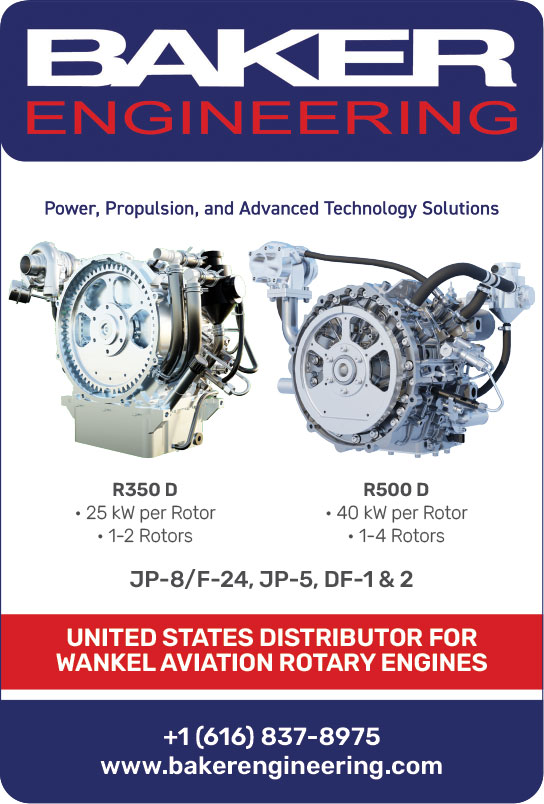
Baked into Wankel Aviation’s engines are some key design differentiators, which we will detail shortly. The principal result of its years of r&d are five different engines: the KKM351d, a 350 cc single-rotor engine; the KKM352d, a 700 cc dual-rotor engine; the single-rotor 500 cc KKM501d; the dual-rotor 1000 cc KKM502d; and a triple-rotor 1500 cc KKM503d. A four-rotor KKM504d effectively displacing 2000 cc across four cylinders is also in the works.
All Wankel Aviation’s engines share similar approaches across their engineering, operation, manufacturing, and both core and ancillary components, with the multi-rotor engines largely being modular expansions on their single-rotor counterparts.
For instance, all are capable of running on a wide variety of fuels including heavy fuels, diesels, gasolines and liquified natural gases (LNGs). Hydrogen-burning versions of the 501d and 502d are also available, with optimisation of hydrogen operations under development for the other engines. As well as all the company’s heavy fuel engines being turbocharged, all engines (regardless of fuel preference) are ECU-governed and liquid-cooled.
In terms of performance, one may note that power-to-weight improves significantly in the engines as rotor counts increase – at 5000 rpm, the 70 kg 501d outputs 45 kW, the 96 kg 502d produces 80 kW, the 123 kg 503d produces
120 kW and the 162 kg 504d produces 160 kW (these figures indicating all-up weight including wiring harnesses). The company has also sought to maximise torque for effectively driving generators and propellers, with the 41 kg 351d generating 50 Nm of torque at 5000 rpm and the 57 kg 352d meanwhile producing 100 Nm.
Further specifications across the board are published on the company’s website. But for brevity’s sake, as we explore the engineering philosophy and design particulars behind this company’s powertrains, we will use the terms
‘350 cc series engines’ and ‘500 cc series engines’ (or approximations thereof) when referring collectively to those Wankels designed with one or more trochoid chambers of the respective effective displacement, given that either group will share most design parameters about their metal components.
Brake mean effective pressure
The intellectual collective gathered in Cottbus was dedicated from the outset to designing and engineering Wankels that would address some shortcomings that it felt were key to the future of effective propulsion (both crewed and uncrewed).
For one, up until the early 2000s, Wankels had mostly (though not universally) been designed to run on gasoline, but from the start, they wanted to run on heavy fuel.
“And today, in the aviation industry, including drones, the tendency is clearly in favour of replacing gasoline with heavy fuels,” notes Fräbel.
“In GA [general aviation], for instance, diesel and Jet A1 are very predominant, owing to standards like CS-23 and the FAR-23, and defence operators are known to prefer heavy fuels, and we expect other markets for small and uncrewed aircraft to follow suit.”
To do so, Wankel SuperTec took a modicum of inspiration all the way from the 1970s through to the 1990s, when Curtiss-Wright, John Deere and Rotary Power International successfully operated large multi-fuel rotary engines, including compatibility with heavy fuels.
“So, to achieve this in small engines, research was first started at TES Wankel in Lindau, with very simple mixture formation and simple HP direct injection [DI] systems. In 2000, when we started on the heavy fuel technology at Cottbus, we switched to using a full EFI [electronic fuel injection] system – so the base engine is our own design, with geometries largely conventional with contemporary rotaries but with some key robustnesses for heavy fuel,” Dr Klotz says.
For instance, the use of turbochargers across all Wankel Aviation engines is key to ensuring sufficient charge pressure for effective heavy fuel combustion within the confines of the combustion pocket created between the rotor and trochoid cylinder wall, including in aviation applications where ambient air densities may vary.
Additionally, aviation Wankels at the time also typically charge-cooled their rotors’ needle bearings, with no use of pressurised oil for lubrication – but this would not suffice for the Cottbus team and their heavy fuel combustion ambitions.
“The reason is that normal gasoline Wankels of the time would have homogenous mixture formation outside of the engine. DI results in stratified charge, as is common also in spark-ignited automotive engines – but this approach risks bringing particles into the engine, and if those get into a rotary’s blow-by, they collect over time in the rotors’ needle bearings because those can’t be sealed in the way that the main shaft bearings can,” Dr Klotz explains.
“That particle build-up drastically reduces the lifetime of the Wankel, that is, with a high AFR [air–fuel ratio]. There was a development in the 1980s converting an existing gasoline charge-cooled rotor Wankel in this way for APU [auxiliary power unit] application in the US, but with such a design only a poor brake mean effective pressure [BMEP] can be achieved – less than 5 bar.”
Hence, Wankel Aviation’s engines instead incorporate a pressure oil lubrication system for their rotor bearings into their overall lubrication architectures (as we will elaborate on later), which resembles the approach taken by Mazda with their rotary cooling.
Some in the Wankel space claim that the Mazda-style oil-cooling approach leads to more weight, complexity and thus inefficiency than more conventional charge- or air-based rotor cooling. Wankel Aviation’s short answer is that those more conventional approaches cause air flow losses en route to the combustion chamber, reducing their BMEP (relative to that of Wankels with oil-cooled rotors); BMEP being – theoretically – a key indicator of an engine’s torque-to-displacement ratio and hence its real-world capacity for driving propellers or wheels.
Its longer-term response has been to build most of its engineering strategy around maximising the efficiency of the Wankel rotary; in particular, throughout its work with key partners on specialised testing such as flow simulations and its own in-house work with Pro/Engineer (now Creo Parametric). BMEP was a primary target for the team, along with the kind of weight and vibration reductions perennial in the UAV engine space.
“Compared with those aforementioned engines that could only achieve 5 bar BMEP, and other, higher-load Wankels with air-cooled rotors that are often capped at 7–8 bar in continuous operations, we aim for a BMEP of 10 bar or more,” Dr Klotz says.
“Solving this first took r&d focus on mixture formation; you can burn jet fuel via homogenous mixture formation, but you’ll warm the fuel, which is bad for starting, and diesel isn’t very compatible with homogenous mixture formation – so we achieve a stratified charge through DI.”
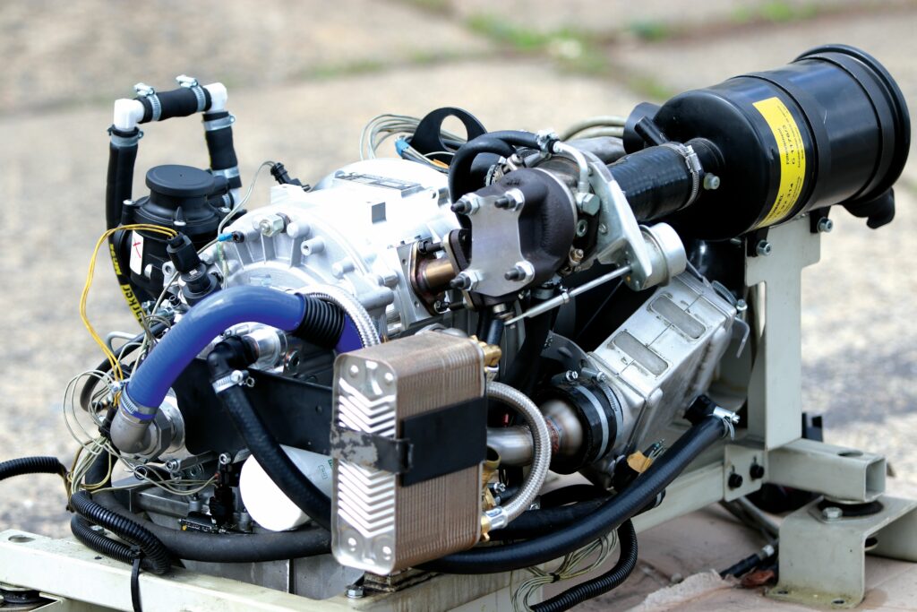
The company’s r&d specific to aviation engines and prototype testing started in 2005, after L3 (through its license fees) provided key development funding to do so, with the first-generation 350 and
500 cc products emerging in the subsequent 3–5 years. Today, flight testing is under preparation and extensive bench testing has been run in Wankel Aviation’s test cells to validate its capacity to work in varying air densities. The engines are proven in numerous terrestrial applications, including one large contract supplying Wankel rotary APUs to 80 of Deutsche Bahn’s diesel locomotives, where they have been in use since 2015.
The first aviation user is expected to be Elfin (a sister company of glider aircraft manufacturer ReinerStemme.Aero GmbH), who will use the engines as hybrid range extenders in their glider aircraft.
“We can customise for varying fuel and operational requirements, although always with a dedication towards keeping the engine metal the same, always using the same, heavily validated mechanical components for safety’s sake – instead, the ECU and the control system must be adapted to each aircraft, including power management systems to ensure power is demanded as appropriate from engine, generator and battery for each flight phase,” Fräbel says.
Part of this research into adaptations has included re-optimising engine mappings and modifications for fuels beyond heavy fuel, diesel and gasoline, including LNG and hydrogen as mentioned. Catering for these various users has also led to extensive documentation of development life-cycles, endurance tests, NVH (noise, vibration and harshness) tests and more for certification.
“On top of not being restricted to one type of fuel, Wankel Aviation’s engines aren’t restricted to aviation either,” Dr Hanisch adds. “We’re currently supplying our hydrogen-powered engines to an EU-sponsored program investigating how switching to very low-vibration engines – like ours – can reduce the negative impacts of ICEs on marine environments, particularly flora and fauna in the ocean.
“We’re also entertaining inquiries from a number of land vehicle manufacturers, where the compact combination of our engines with generators, and our ability to run on diesel as well as gasoline, works very well for military users. They will use different fuels for their vehicles, and occasionally want engines that can function as ground generators. So USV and UGV manufacturers alike could find it beneficial from a demand point of view to integrate our engines.”
Operation
Starting power for the company’s Wankels depends on specific applications and the degree of hybridisation, with both directly mounted starter-alternators and separate starting motor drives being compatible with the engine mechanics.
“We’ve used many variations on that; Deutsche Bahn for instance wanted something simple, so we integrated asynchronous electric machines with single pole pairs – running the engines at 3000 rpm to output alternating current at 50 Hz is a disadvantage – but DC output for battery charging via a rectifier avoids this speed setting. We’ve also tried different permanent magnets for higher pole counts and better power-to-weight ratios, including some quite unique designs from specialist electric motor companies,” Dr Klotz recounts.
Starting and operation are governed by the ECU, which is produced in-house. “We initially planned to use a total system from Delphi including the ECU, but didn’t get the support; so, we switched to an aftermarket system, with ability to modify it for the 500 cc engine. It worked but support was expensive, and I felt it was unsuitably large, especially for our small 350 powertrains,” Dr Klotz continues.
Hence, the Cottbus team thereafter started hardware and software engineering for its own ECU, which largely follows standard OEM-type designs for ICEs, with specific modifications to suit rotary engines.
The primary point of note here is that the power output levels in the ECU mappings are primarily targeted by varying fuel input; no throttle is installed. The air port downstream from the turbocharger is thus open into the combustion chamber, and integrates sensors for air flow, pressure and temperature, enabling the ECU to track and match fuel injections to incoming air properties across the power band and at varying altitudes.
“We follow standard automotive ICE development processes for the ECU software, beginning with on-paper calculations before programming directly into an assembler without any high-level languages,” Dr Klotz says. “So, the software covers basic functions for now, with mapping for steady-state operations, and some key expansions beyond that for dynamic requirements without automotive-type on-board diagnostics just yet. For CAN-bus communication to externals, we implemented a protocol based on SAE-J1939 and we’re also able to quickly modify the ECU for application-specific requirements.”
Fräbel adds, “The design process for now has achieved clear compliance with DO-178C DAL C, with reliability data from the field showing no problems with the software. We also anticipate that additional key safety assessments can be made by the aircraft at a functional level that will enable aircraft integrating our engines to fit the assurances of DAL D, including its standard that the ECU source code fulfils the high-level requirements.”
Key areas of custom work include the direct fuel injectors because COTS DI components are largely built for reciprocating engine cylinders, and hence very different injection timing principles than that seen in Wankels.

“The basic principles are the same; intake followed by compression, then ignition at top dead centre followed by expansion and exhaust,” Dr Klotz says. “What’s very different between reciprocating and rotary operations are the angles of the shaft relative to operating phases.
“A Wankel rotor has three shaped chambers, and its gear has a 3:1 ratio with the fixed gear such that each full rotation of the rotor takes three rotations of the eccentric shaft. So, there’re three full four-stroke combustion cycles per rotor revolution, but on average one cycle or just one combustion per shaft revolution. With one injector for all three ‘chambers’, that injector fires at the same shaft angle each time, so the mechanical design and the programming of the solenoid actuator needs to be updated accordingly.”
The engines also use a high-pressure, mechanically driven fuel pump, which Wankel Aviation has customised from a standard automotive plunger pump design to reduce its weight down to roughly 250 g, also enabling it to fit within the constraints of the accessory housing.
While Wankel Aviation is open to custom turbocharger designs to suit aerospace requirements, for operations up to 3000 m ASL, it integrates off-the-shelf turbochargers such as those from Garrett Motion. A GT 1241, for instance, is often used on the 350 cc engines, particularly in the series hybrid application for German Railroad, where just 15 kW of continuous electric power are supplied, and thus a turbocharger that is undersized relative to the engine can be installed to keep the weight down.
“We tend to integrate exhaust pipes from the engine to the turbocharger as befitting each application, making sure not to have excessively long pipes, but otherwise we keep to simple components there,” Dr Klotz says. “The overlap between inlet and outlet has to be greater in a Wankel than in a reciprocating engine, which means one has to ensure that the turbocharger’s backpressure isn’t too high – and that’s influenced by the pressure drop inside the exhaust pipes. So, choosing components with low flow drop is key.”
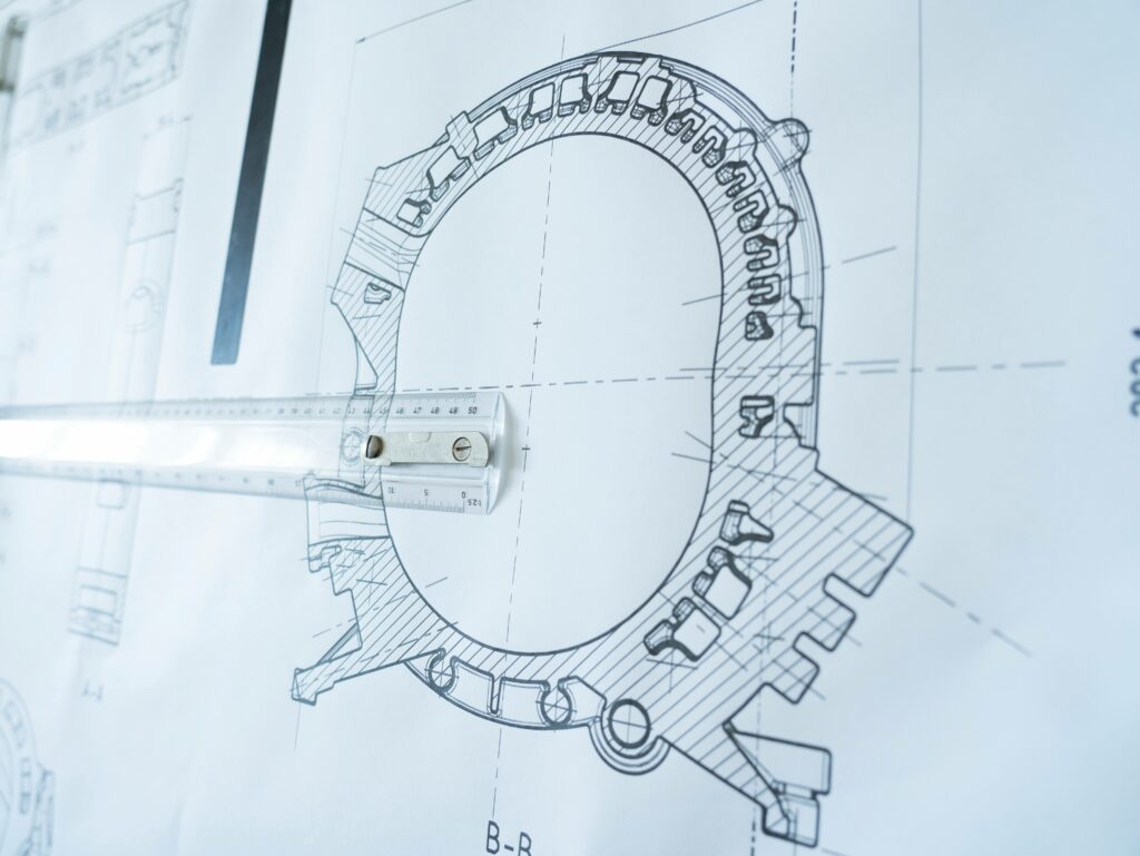
Chamber geometries for fuel–air mixing were based first on engineering fundamentals from Wankel SuperTec’s predecessors in the 1980s, with Wankel Aviation having since applied modern 3D CFD flow simulations to get closer to its goal of a homogenous mixing and stratified charge.
“There’re widely available tools from AVL and similar organisations for achieving this, and the simulations indicate that there’s still further mixing optimisations we could achieve in a future generation of the design,” Dr Klotz says.
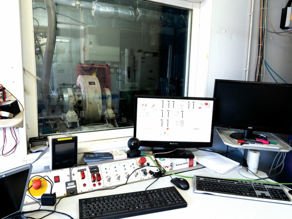
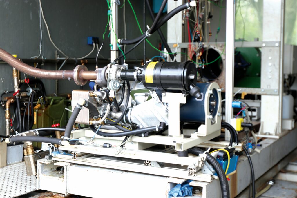
“Simulations are one thing, of course. To actually prove our designs thus far, we have two test benches built to closely resemble those in TU Brandenburg’s test cells. One is a sophisticated dynamometer with an extensive DAQ-system for development work, and the second one we built is more tailored to application-specific requirements but simpler in DAQ – we used the latter in verification tests for the units going to Deutsche Bahn. Both integrate brakes and data acquisition systems, and run in environmentally controlled test chambers as is standard.”
The ignition system uses a single spark plug per rotor (owing to the small size of the combustion chamber), with a coil integrated externally to optimise engine packaging, and ignition timing is mapped into the ECU based on speed and load requirements, with an incremental wheel on the eccentric shaft to ensure a correct crank angle per spark.
“We use an interrupt control system to ensure precise matching of timing requirements, with regard to initiation of ignition.”
Dr Klotz adds, “As we’re performing spark-assisted combustion of heavy fuels and even diesel, we don’t use capacitive discharge ignition; it’s more robust to use an ignition magneto because it gives a more prolonged spark duration. We’ve also selected our plugs based on requirements for the size of the electrode opening because that influences backflow and can therefore cause combustion efficiency losses if you don’t optimise for it.”
Future versions of the engine may integrate a second spark plug, either for redundancy or for further combustion optimisation, the latter likely being a configuration with leading and trailing plugs as used by Mazda – so long as it can be made functional with DI.
Oil lubrication and cooling
As mentioned, the oiling system in Wankel Aviation’s engine approach serves two critical purposes: cooling of the bearings (at rotor and shaft) and the rotor itself, as well as lubrication of both the bearings and gears. Most notably with respect to our previous studies on Wankel rotary engines, oil cooling is the core of Wankel Aviation’s strategy for thermally managing the rotor bearings.
As some readers may recall, every Wankel manufacturer previously featured in this publication has opted for at least somewhat of a different approach to cooling the rotor’s needle bearing; a critical engineering issue given the tight proximity between that sensitive bearing and the severe heat and harshness of the combustion chamber.

For example, Advanced Innovative Engineering’s rotaries (investigated in issue 7) utilise their own self-pressurising blow-by gases as a medium for cooling the needle bearing, extracting them via the rotor side seals using the suction of an internal fan driven off the crankshaft and then blowing them through the bearing before they pass into a heat exchanger.
As another example, Rotron (first featured in issue 4, then revisited eight years later in issue 49) can uniquely use their Wankels’ exhaust gases to effectively create an internal Venturi pump, which draws in cooling air that swirls inside the ‘lemon’ – a lemon-shaped aperture conventional in Wankel rotor designs – to extract heat from the bearing on its way through the engine.
Two operational factors drive the differences in Wankel Aviation’s approach to those we have previously featured. One is that its rotors feature no needle bearing at all, given their cited disadvantages with respect to heavy fuel efficiency. Instead, the rotor is designed to run on a plain bearing, which overcomes those disadvantages but inherently needs more oiling than needle bearings owing to its slightly higher friction in operation.
The other is the additionally cited disadvantage of charge cooling the rotor with regard to BMEP maximisation (and several of the approaches to rotor cooling used by UAV Wankel OEMs today revolve around some use of charge cooling).
Hence, a detailed and comprehensive oiling strategy is paramount to addressing both of these factors. The 350 cc engines are typically built with a wet sump because they were originally designed to meet a tight set of cylindrical dimensions ideal for propeller drive and similar applications (although they can be designed with dry sumps upon request). The 500 cc engines, meanwhile, were designed with more freedom and flexibility, and are therefore each constructed with a dry sump as standard, with both engine families integrating an oil metering system.
The importance of that oil metering system comes from the small degree of oil losses that is incurred in operations attributable to minute excess splashes across the rotor side seals into the territory of the combustion chamber and exhaust port.
“So, all our rotary engines have an oil metering system, which functions using specialised pumps to feed about 20 g/hr from the reservoir sump – depending on load – to each trochoid housing, with the apex seals then feeding an initial film of non-pressure oil to the inner surface,” Dr Klotz says.
“For the shaft and rotor bearings, oil from the sump – whether the pan or the external reservoir – is drawn out using a pressure oil pump, which feeds it into an external cooler that may be an oil-to-air or oil-to-water cooler.”
In the 350 cc engines, the pressure pump runs by way of an accessory housing driven by the eccentric shaft (which also drives the liquid coolant pump for the housing), while in the 500 cc engines, both pumps are mechanically gear-driven off the shaft, with the latter’s housings designed differently from the former category to accommodate space for those gears and pumps.
“From there, it’s re-fed to the engine, where it’s then distributed onto the main bearings of the eccentric shaft, running over that centrifugally and also inside of the shaft via drilled channels,” Dr Klotz continues.
“Through those, the oil gets delivered both to the eccentric shaft – to externally cool the rotor – and to a hole designed to spray oil inside the rotor – to directly cool and lubricate the plain bearing.”
From inside the rotor, the oil gets thrown back to the shaft’s main bearings, and ducts inside the bearings run to drain the oil, either back to the pan in the 350 cc series engines, or back to the dry sump in the 500 cc engines via a suction pump, which is mechanically and operationally similar to the pressure oil pump, although built slightly larger to make room for any potential foaming of oil on its way out.
If a 350 cc engine should be constructed with a dry sump, it too will integrate a suction pump, although Wankel Aviation does recommend against this customisation direction for the single-rotor 351d, viewing such a specific weight increase to its smallest, lightest engine as somewhat inefficient. Because the suction pump does not have to build up pressure, an external, electric-drive device with manageable power demand can be applied.
“We have, by contrast, happily delivered a modified 352d – our twin-rotor engine with two 350 cc housings – with a dry sump. In that larger engine, the relative weight increase wasn’t so noticeable,” Dr Klotz muses.
Naturally, installing a wet sump in a Wankel engine similarly to a reciprocating engine – that is, with little separation between pan and crankshaft – would be problematic for effective sealing, and thus for compression and exhaust also because blow-by gases would ‘catch’ on the pan or the filter or aperture leading to it.
“Instead, we have two oil seals, one between the shaft and the rotor and one between the shaft and the housing. Together with the gas sealing system on the rotor side, these form a small space where the blow-by is ducted out by holes separate to the oil pathway, keeping the two almost completely apart,” Dr Klotz explains.
Water cooling
While oil is the cooling medium for the rotors, conventional water–glycol is used to thermally manage the housings themselves, and the two Wankel Aviation engine families bear very slight differences in their water-cooling systems.
“In both, you start with an inlet, where a mechanical thermostat may be installed as an option to track for when the engine is cold so that coolant doesn’t pass outside of the engine into a cold environment. From there, it runs into a centrifugal flow pump and into the housings, being distributed into the side housings and the trochoid housings,” Dr Klotz explains.
“Here is where the differences between the 350 cc and 500 cc come up: the latter, as manufactured, has a peripheral cooling duct, whereas in the former, all cooling fluid just runs axially, as per Mazda’s Wankel engines.”

The reasoning for this comes from Wankel Aviation’s ambition to die-cast the 350 cc engines once order volumes grow large enough for cost-efficiency: the trochoids can be die-cast with axial cooling ducts but not with peripheral ducts, which must instead be created via sand casting.
“Both ducting approaches have their well-established advantages and disadvantages but, in principle, both are effective at thermally managing the housing,” Dr Klotz says.
An astute approach to water cooling is critical for preventing a huge thermomechanical differential around the trochoid housing, which often risks shortening Wankels’ time between overhauls because their combustion-to-exhaust end becomes very hot and their intake end relatively cool during prolonged high-load operations.
“For our part, we considered this problem closely from the earliest design phase; we made sure in our first relevant drawings to have enough flow speed and surface optimisation to efficiently transfer heat from the housing to the coolant and to even-out the thermal differentials,” Dr Klotz comments. “And with aluminium materials and our proprietary coatings, you inherently get a good spread and transfer of heat.”
Hybridised and hydrogenised
While the core components of the company’s rotary engines are effectively set in their designs, Wankel Aviation plans to continue developing its upcoming four-cylinder KKM504d, as well as alternate configurations of their control and ancillary systems to optimise for the varying demands of today’s aviation markets.
To reach broader markets, the company has agreed a deal with Baker Engineering, with that Michigan-based company having thus become sole licensed distributor – and manufacturer, should local manufacturing be merited – for supplying Wankel Aviation’s engines throughout the United States.
In terms of future development directions, one already mentioned is hydrogen combustion, and the company is actively working on several projects in this regard, with at least one unnamed aviation customer among them. Wankel Aviation has built and delivered that customer’s first engine, which features minor modifications; the German company has also agreed with the customer that it will provide a second, more extensively modified engine to further optimise for hydrogen operations based on data from the first unit.
“It’s particularly important as this customer wants to fly on liquid hydrogen in the long term because of its volumetric storage advantage over gaseous hydrogen; it’ll be a new challenge for us, but we’ll learn a great deal that we can then offer to other customers,” Dr Hanisch adds.
“But we’ve been running engines on gaseous hydrogen since 2019, and so we know what problems we do and don’t have to account for. For instance, too many people claim or believe that sealing hydrogen is difficult because it’s the smallest atom and should therefore squeeze through other molecules. But those other molecules are working to hold the hydrogen in too; they’re not just sitting there but are linked through chemical bonds and form an effective grid.”
As Dr Klotz explains, “The real primary issue with engineering for hydrogen combustion is maximising your power output without causing self-ignition by running too rich. Thus far, we’ve taken some lessons from Mazda’s approach, using direct inflation of hydrogen during the compression phase to enable a bigger charge and higher power with the same air–fuel ratio, along with some other minor reconfigurations like making the housing walls a bit thinner and running the engine at lower power. That enables stable operations without decreasing the power-to-weight ratio.”
The other continuing pathway for Wankel Aviation is hybridisation, including one project to develop a parallel hybrid aircraft powertrain together with Elfin. As of writing, the company has concluded a key meeting with DLR (the German Aerospace Center) on mathematical modelling for that powertrain – which will integrate a battery and generator such that they can power the propeller independently of the Wankel – and is developing the aircraft requirements in MATLAB Simulink for now.
“Afterwards, we will filter down the requirements into the currently anticipated architecture of the propulsion system, such that the power management system will be able to seamlessly and digitally balance load requests across both the battery and the engine, as part of a FADEC; this will also require some reconfigurations of our ECU to receive and process commands from the power management system,” Fräbel tells us.
He adds that this project stands to substantially enhance Wankel Aviation’s aptitude for integrations and customisations on behalf of UAV customers: “You really need a clear mathematical understanding of the aircraft at hand to be able to help with customer-specific optimisations.”
Hence, the team at Cottbus is looking forward to starting its flight-testing program at the beginning of 2026 – having fully validated its core engine technology – to better understand its in-flight physics, and henceforth to optimise its control laws and in-house digital mathematical models.
“But what we really want right now is highly qualified personnel who can help us understand and independently validate the UAV designs we’ll encounter, particularly the interactions of our powertrains with complex carbon fibre aerostructures, so as to flesh out the insulations, control implementations and so on,” Fräbel continues.
“We know that in aviation design, particularly composite material aircraft, you can make many, many mistakes with regards to the engine integration. So, we’re actively looking for people with ideal engineering expertise, so as to facilitate lengthy and successful partnerships with UAV customers and ensure that we’re more than just a supplier of engines for UAV manufacturers.”
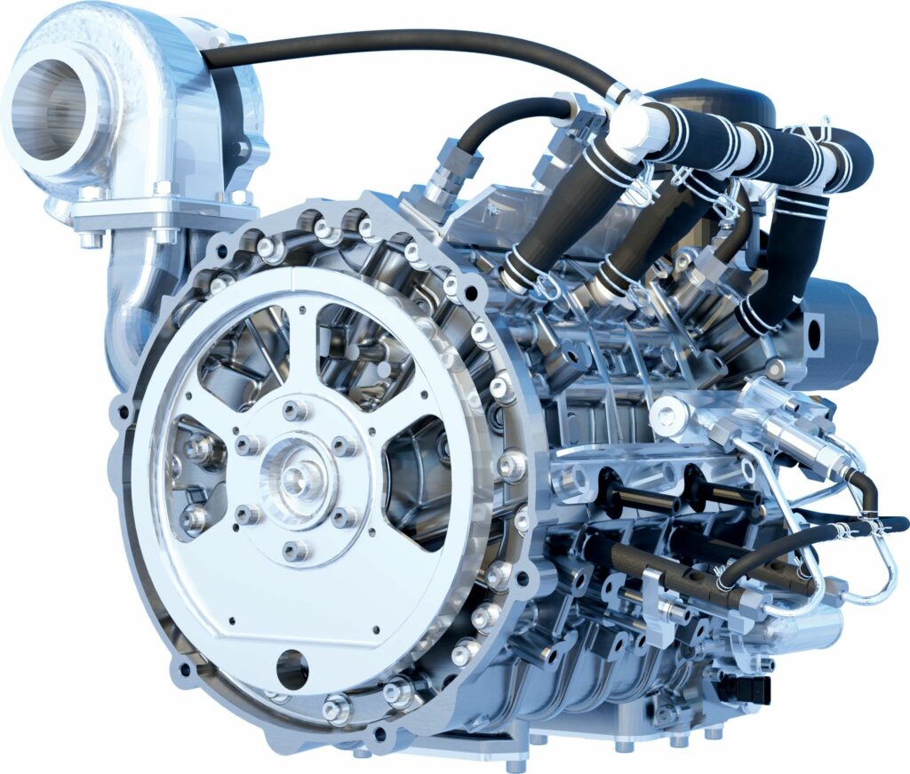
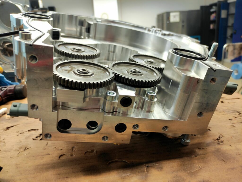
Anatomy
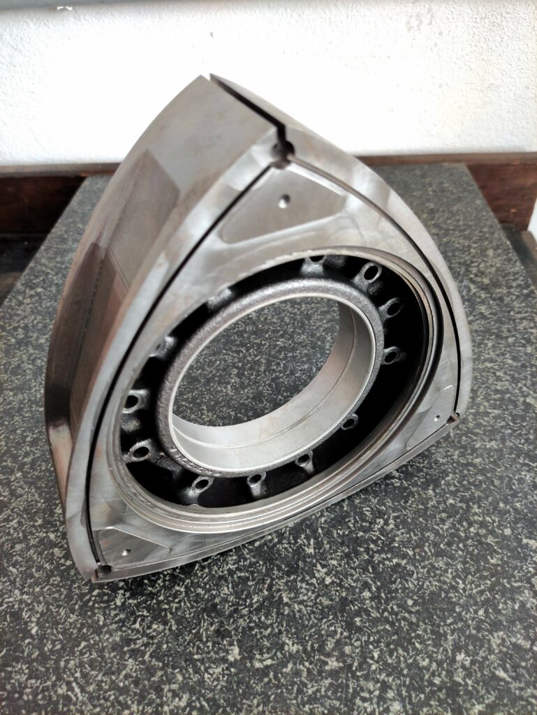
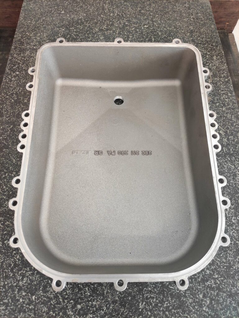
The housing assemblies of Wankel Aviation’s engines are largely conventional, with single piece trochoid rotor housings (coated internally with proprietary materials and treatments), side housing plates and mid-housing plates, each rotor chamber being roughly 250 mm long. These are all produced from aluminium alloy, with the actual type depending on whether the parts are machined or cast, as is an additional accessory housing – typically mounted on the rear and conformal with the engine’s height and width – for integrating pumps and a starter-generator that run off the crankshaft. The 350 cc series engines also bolt an aluminium oil pan underneath as a fifth housing component.
As of writing, all these parts are sand cast, although the 350 cc series engines’ housings will likely be die-cast once order numbers are high enough to justify the expense of manufacturing suitable moulds. Those smaller engines can also be CNC machined from billet for cost-optimising and speeding-up orders of individual units.
The rotor is nodular cast iron for its strength and cost advantages; titanium or other more exotic materials may be used for more demanding aviation applications in the future. Steel meanwhile has been tested and forgone owing to its inferior noise damping compared with the current choice of iron and to the greater difficulty in producing quality steel rotors (which would typically merit machining followed by heat treatment).
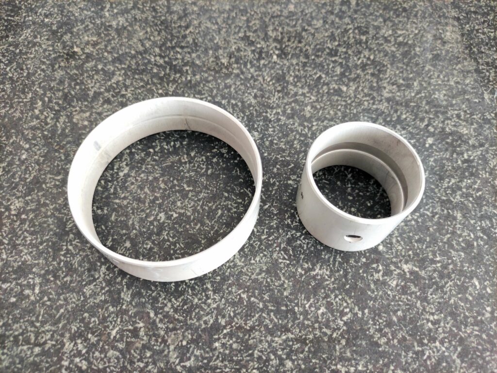
The apex seals are industry-standard ceramic, single piece components, while the side and corner seals are cast iron. The apex seals are hence significantly more costly, but deal effectively with the harsher mechanical and thermal conditions they must endure, and benefit from long lifespans.
The seal inserts are precision ground to tightly hold the seals without special coatings, and without excessive crushing of the seals during thermal expansions. The seals are also designed with springs to maintain pressure against the trochoid walls if wear or minor damage should occur.
As the rotor is oil-cooled, with no need for air or charge to pass through it for cooling, it is designed as a solid (rather than open) component; hence, splashed oil can run over its solid surfaces to collect in the bearing and no airflow losses to BMEP are incurred. All bearings in the company’s engines are conventionally designed plain bearings featuring an outer ring, an inner ring and a seal in-between.
Naturally, the exact count of bearings varies with the number of rotors: the eccentric shaft runs in one rotor bearing, plus one more bearing for each side and mid-housing plate; hence, a single-rotor engine has three bearings, a dual-rotor five bearings, the tri-rotor 503d seven, and the four-rotor 504d will use nine.
To ease shaft manufacturing and assembly, Wankel Aviation uses a split shaft design, in which each eccentric shaft is made from at least two standardised parts: an end-side shaft part and a driven-side shaft part. Dual-rotor engines can thus use shafts assembled from one end-side part and two driven-side parts; each part being joined by way of a metallic tie rod interconnect. The face of each shaft part end is machined with spur gear teeth for a long-lasting fit and precise geometric orientation (which is easily validated via QC), and secured into the tie rod with bolts. Shaft parts cut similarly can hence be used by any engine, regardless of rotor count.
The eccentric shaft pieces are machine-cut from industry-standard, high-strength steel alloy (and the fixed and rotor gears are similarly cut from steel as is conventional) before having their oil passages drilled, with a final grinding of the end spur gear teeth and bearing journals following. Additionally, regardless of engine size and rotor count, the frontal protrusion of each shaft is additionally ground for mounting a flywheel (vital to torque-balancing in Wankels) and the rear protrusion is ground to mount a drive gear for the accessory housing.
Key suppliers
Machining of housing parts: Kaden & Salwiczek GbR
Machining of accessories for housing parts: HERO CNC
Foundry casting of housing parts: Werner Lichy Modell- und Prototypenbau e.K.
Sealings: Gesellschaft für Dichtungstechnik mbH
Starter-generators: Hi Performance Electric Vehicle Systems Inc.
Turbochargers: Garrett Motion
Components for hydrogen supply systems: HYDAC New Technologies GmbH
Flow simulation software: AVL
UPCOMING EVENTS


