


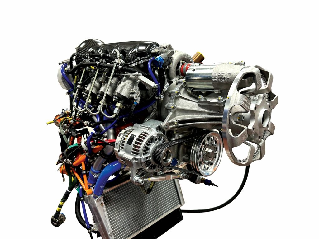
Groupe Danielson Trident 100 TD2 turbodiesel
(Image courtesy of Groupe Danielson)
Haute qualité
A decade on from our previous report, Groupe Danielson has grown enormously, now boasting full in-house manufacturing and servicing capabilities, as well as growing maturation, success and support for its Trident UAV engines. Rory Jackson investigates
Just over 10 years ago, we featured Groupe Danielson’s Trident 100 TD2 engine, a 1.1 L, inline three-cylinder turbodiesel designed specifically for the UAV market.
Since the company’s 2014 public launch of the Trident series of engines at AUVSI Xponential (where our colleague researched the 100 TD2 for Issue 2), Groupe Danielson has undergone tremendous growth to support rapid and large-scale manufacturing of customised engine components.
This was not just for its own engines, but for the engines, vehicles and miscellaneous mechanical parts of dozens of major European OEMs across the aerospace, automotive motorsport industries and more (with aerospace and defence giants Safran and Airbus among those who routinely call on Groupe Danielson for casted, machined and welded parts).
Key drivers of that growth included a €7.5 m production-focused investment into a new 2400 m² foundry and a 5-axis machining centre that commenced in 2017, followed by a €1.3 m investment round into enhancing production quality through new furnaces and sand-casting capabilities.
Today, the company numbers 130 employees and takes on around 300 unique projects annually; however, the Trident engines remain the centre of their focus.
The Trident 100 TD2 continues to be Danielson’s flagship product, boasting the highest technical-readiness of any of its engines and, at the surface level, the details of the engine design and operation closely resemble those that we published 10 years ago. It remains a compression-ignition (CI), four-stroke i3, with mechanically-governed direct injection (DI), water- and oil-cooling, an integral 1.28:1 propeller gearbox, optimised for a high power-to-weight ratio (outputting 74.6 kW or 100 bhp, while weighing 75 kg dry and 120 kg all-up).
(Image courtesy of Groupe Danielson)
Make no mistake, extensive maturation and validation of the engine’s design and technology have occurred since our previous investigation. While the majority of formative r&d was completed between its conception in 2006 and its launch in 2014, the 100 TD2 received its first major customer – and commenced active commercial flights – in 2018.
Although that initial company declines to be named (we can state that it is a large European – but not French – military organisation), it kick-started a surge in real-world flight hours for the
100 TD2, with over 12,000 hours accumulated since 2019 (roughly 3500 in European airspace), and 15,000 hours anticipated before the end of 2025.
Contributors to those hours include three different customers in the UAV space, with one major European UAV manufacturer having validated its altitude performance at 7000 m (bench tests having affirmed it should continue performing nominally at 10,000 m).
With 70% of the 100 TD2’s components manufactured at Groupe Danielson’s facilities in Magny-Cours, the engine is both ITAR/EAR-free for shipment and export, with 50 units having been sold as of May 2025. Those facilities have been certified to ISO 9001 and EN 9100 by Bureau Veritas.
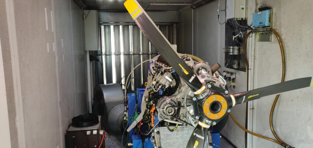
The group’s extensive testing facilities include a propeller testing cell for gauging the efficiency of different prop integrations, four dynamometer bench testing cells for cycling engine and gearbox arrangements, and two aerotherm cells for investigating how engines and platforms perform in varying environmental conditions. Co-located with Danielson at Magny-Cours is a large wind tunnel owned by Aero Concept Engineering, with whom the engine company works closely for both high- and low-level CFD studies.
As Benoît Delaporte, assistant director of Danielson Aircraft Systems (DAS), tells us, “For certification, we have been following EASA’s CS-E [Certification Specification – Engines] guidelines as our reference standards. When we test the 100 TD2, we use the redlines of CS-E to define the rigours, limits and so on of how we test it, except those aspects meant for spark-ignition [SI] engines.

“CS-E has provided us first with a general testing context, that is, what you can and cannot do. Following that, we performed the CS-E [subpart 440]
150 hours endurance qualification test, including cycling it up to full take-off power and back down, repeatedly, and in different fluidic surroundings as well as considerable heat. We’ve also completed its regimen for 100 startups-and-stops, the goal being lifetime-representative testing of the engine.”
Danielson completed several other tests according to CS-E standards, including the CS-E 340 vibration tests, which involved cycling the 100 TD2 with one of its three injectors disconnected, confirming that it can be flown to safety on just two active cylinders, and the CS-E 400 overspeed tests to affirm that it will not explode or suffer similarly undesirable failure modes when run too fast for short periods.
The manufacturing and testing complex at Groupe Danielson is utilised by both DAS and Danielson Engineering (DE). The former focuses on integration, qualification, flight testing, MRO and other services for the Trident engines, as well as aircraft engineering and consultation. The activities of the latter are pushing development of the ExSTOL, which is a 1050 kg fixed-wing UAV platform running on two nacelle-borne 100 TD2s.
DE, meanwhile, provides extensive engineering services to DAS and many other customers (including those alluded to above), encompassing prototyping, development of combustion systems, engineering of powertrain proof-of-concepts, adaption and functional validation of powertrains to platforms, and small batch manufacturing and assemblies of new powertrains products and parts.
(This and all subsequent images courtesy of the author)
Danielson received us at its Magny-Cours location in May 2025, where we were guided in meticulous detail through all its facilities and received an understanding of how it has made the leap from small engine developer to full-scale powertrain manufacturer, and how it has made the preparations necessary for producing, customising, quality controlling and servicing its engines for users around the world.
100 TD2 evolution
While Danielson has a long heritage in CI engines, a CI design was chosen over SI in developing the 100 TD2 in pursuit of greater fuel efficiency (owing to the higher compression ratio and lack of fuel throttling of the former), and wider appeal to defence customers who often have better access to heavy fuels than to gasoline.
Meanwhile, the fuel and control system architectures are designed with inherent advantages to the engine’s resilience. For the former, each cylinder has its own individual fuel pump, and each pump functions using an internal piston driven by the 100 TD2’s single overhead camshaft (as are the inline intake valve and exhaust valve of each cylinder). Fuel injection quantities are metered mechanically, with a single fuel lever near the back of the engine that is actuated via an autopilot-controlled linear servo; the lever runs into a command rod, whose position governs the pumps’ freedom of movement and hence, determines the quantity of fuel that each can deliver to its cylinder.
“Modern UAV engines are full of electronics that emit EMI; hence, controlling the engine with single or even dual-redundant ECUs poses a precarious source of possible failures, whereas our mechanical DI is unaffected by EMI and tested to operate without failures for dozens of continuous hours in extreme conditions,” Delaporte says.
“And an ECU may be useful in a road vehicle, which runs at many different speeds and needs many complicated maps. But a fixed-wing aircraft has a high-speed mode for take-off and maybe mid-air boost, its cruising speed, and maybe a slowed descent speed – three very simple speed changes, easily achieved by having the autopilot pull or push the lever to alter fuel and hence power delivery.”
Notably, the DI fuel system also avoids use of a single common rail, which would have posed a single point of failure. Recent readers may remember that DeltaHawk (featured in Issue 54 for its DHK180 twin-charged V4 diesel) also chose to forgo ECUs and common fuel rails while (successfully) pursuing FAA-certification.
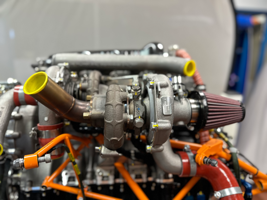
Induction is forced via a two-stage turbocharging system mounted on the upper-left side. Air is first drawn in through a modular intake pipe that can fit any standard air filter, passing into the ‘low-pressure’ first stage, which compresses the ambient air, preparing it (whether sitting on the ground or cruising at very high altitudes) for the ‘high-pressure’ second-stage turbo, located forward of the first stage.
From the first stage, the prepared air runs through a first pass of the intercooler (sitting below the two turbochargers) before running into the second stage. The fully compressed air then passes through the intercooler once more, and into a plenum integrated with the cylinder head, by which the air is fed into the three cylinders.
“The second stage enables the high compression ratio for the engine’s power output, while the first stage exists solely to compensate for low-pressure air at altitude,” Delaporte explains. “The drawback is that when you’re on the ground, the first stage’s efficiency is poor, but much like the camshaft, valvetrain and most other mechanical components in the 100 TD2, it’s configured to work very efficiently at the user’s cruising altitude, which is where they will be for the vast majority of mission time. So, adding something like a bypass valve would have conferred no particular advantage.”
Lastly, a proprietary torque smoothing system installed between the crankshaft and the fixed-ratio gearbox mechanically absorbs some of the force from torque spikes immediately following combustion, and reapplies it during the torque troughs prior to combustion, thereby providing the damping benefits of a flywheel to the engine’s torque acyclicity, without the excessive weight of such a component.
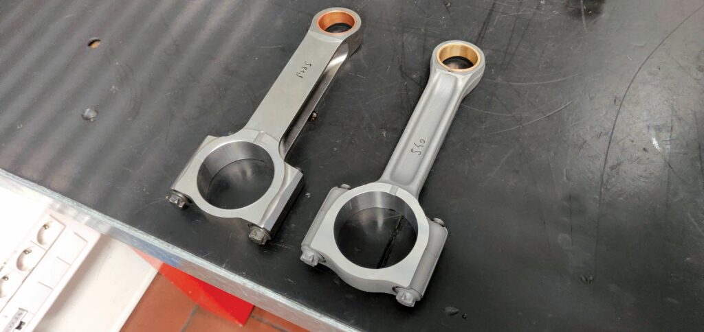
Of the engine’s core components, most changes since our last feature have been minor, intangible design alterations to better aid manufacturing and servicing capacities. The best example of this is the new connecting rod design. Previously, the con rods were cut directly from steel billet as H-beams, and then machine-ground to defined tolerances, before being finished with a shot peening process to improve their long-term fatigue resistance.
“After being shot peened by a partner, the con rods would come back to us, and we’d grind the big and small ends to final tolerances, and install a bronze bushing in the small end and a conventional tri-metal bearing in the big end, making certain at each stage that the centre-to-centre distances were accurate,” Delaporte says.
“Today, however, the con rod is a forged steel I-beam part. Size-wise it is exactly the same as the old rod – still a two-piece made from 35NCD16 – but the cost per unit is now much lower because it goes through less material and fewer steps per part; we just receive the forged rods in-house, and do the end machining and bushing installation.”
Additionally, the cylinder head has changed little from that of 10 years ago, but Danielson has integrated some bosses for sensor installations, which we explain further below.
“Sincerely, we take pride in how little of the core engine has changed in the last 10 years, because it validates that the base design we chose was inherently stable, and it’s enabled us to collect lots of experience, and understand how it works in the years since,” Delaporte notes.
Output changes
As one might expect, accumulating several thousand hours of real-world flight data has spurred improvements to subsystems ahead of the propeller gearbox.
Most extensive are those to the clutch used for engine starting. While a centrifugal clutch previously sat just downstream from the gearbox, on the DLC-coated propeller shaft, Danielson sought a more efficient and consistent approach.
The new clutch design features an alternation of two types of discs: five discs cut with internal splines, and six cut with external splines and featuring molybdenum-coated faces for friction, with the discs held and compressed together using Belleville washers.
“This design has three functions: first, during the few seconds when the engine is starting and below idle, the torque smoothing system may act counterintuitively, making torque acyclicity worse. So, the clutch absorbs and slides when there is overtorque, without which there could be damage to the gearbox,” Delaporte explains.
“Second, a propeller strike can put an overtorque into the crankshaft, and damage the engine’s internal components. So, again, to avoid damage, the clutch slides in response to an overtorque. And lastly, if an injector fails and we have misfiring in just one cylinder, the engine needs to work on just two cylinders – but that makes operations much more acyclic. Instead, the clutch slides when torque gets too high, smoothing the force to the propeller, and helping the UAV to fly safely back to the airbase.”
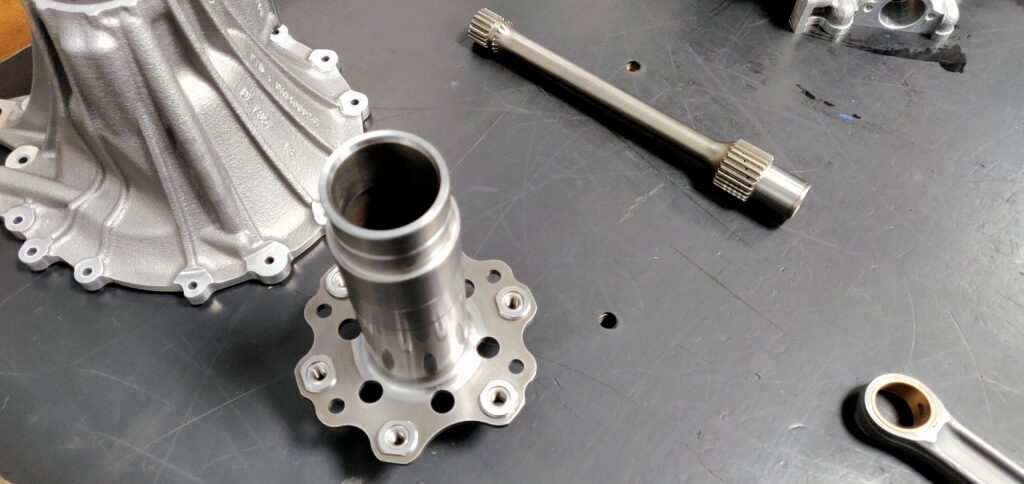
The third fault case requires very high heat dissipation from the sustained friction between the discs. Aiding that is a quill shaft running inside the hollow propeller shaft. The internally-splined clutch discs ride on a sprocket on the quill shaft, which features multiple small oiling holes that provide both lubrication and cooling between the discs.
“That’s the benefit of the quill shaft with respect to the clutch. But more importantly, most power from the gearbox transmits to the propeller not through the propeller shaft but through the quill shaft,” Delaporte adds.
The propeller runs with a very regular speed thanks to the torque smoothing system, which accelerates to absorb energy and decelerates to restitute energy. However, this creates a very small rpm delta between the prop and crankshaft. So, the quill shaft is made from a steel that is also used in Formula One springs, such that it can flex to absorb energy without net loss of energy.
Lastly, the propeller gearbox case has been redesigned to accommodate the new propeller shaft and clutch designs, while also integrating the starter motor and an altered oiling hole to keep the propeller shaft bearing lubricated.
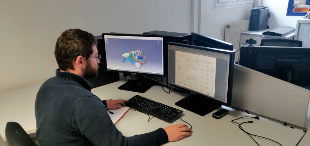
CAD
Given the importance of customising new engine designs to suit specific customer requirements, Danielson’s growth over the past decade has equipped it with several departments and stages ready for rapidly prototyping new Trident engines and preparing them for scale manufacturing.
The first of these departments in DAS is dedicated to CAD processes, particularly for conceiving digitally how an engine may be integrated into a new vehicle or platform.
That typically involves taking the core engine design and considering all the forms of mechanical interfacing, threading, thermal management systems, and electrical and electronic ancillaries that are compatible with the customer’s platform.
“Cooling systems especially are often forgotten at the early design phase; but thanks to data from our aerotherm testing cells and wind tunnel, we routinely simulate how the customer’s engines will perform in temperatures up to 55 C, based on different radiator and baffle configurations within their platform, as well as how those might influence drag about the vehicle,” Delaporte explains.
Additionally, to cover airworthiness from this early stage, any integration uniquenesses or modifications are performed to CS-E standards, Danielson’s engineers continually check that their designs and simulations comply with EASA specifications (as do the testing engineers later, for any unique engine, subsystem or mounting bracket prototypes).
“Manufacturing is similarly carried out in adherence to standards, with the design team also doing first-stage modelling for any new tooling we need, such as assembly jigs or casting moulds,” Delaporte adds. “Of course, it’s important to simulate how the engine or any new parts will perform under a huge range of conditions, which is where the dedicated, separate, simulation department comes in.”
Simulation
The simulation department at DE specialises in four principal capabilities, each conducted via a preferred software tool, to perform modelling-based r&d for Trident engines and Groupe Danielson’s customers.
First among these is finite element method analysis for mechanical and thermal modelling, which is performed using Abaqus FEA. Next, is its in-house CFD modelling, for which Danielson’s simulation engineers use STAR-CCM+. The company also performs 1D simulations using GT-POWER, for numerically modelling assemblies of parts in a time- and RAM-efficient manner, and it also simulates combustions inside given engine designs using Converge CFD.
These tools and capabilities have enabled a wide array of research projects for ways to either enhance or validate veritably every facet of the 100 TD2, and improve other engines and vehicle subsystems also, as Florian Durieux, numerical simulation engineer at DE explains to us.
“Some years ago, for instance, we studied whether shrink-fitted, steel cylinder liners could work in the 100 TD2, in place of the plasma coating, by simulating the mechanical stress on the liners that would be caused by contact pressure and thermal differentials during operations,” he says.
The simulation team has also performed complex FEM analyses, such as dynamic vibration modelling of the entire engine, to unearth how mechanical stress evolves and spreads throughout the engine structure during a full cycle. Other FEM studies investigated contact pressure distributions across cylinder head gaskets, and resolved a crack that formed in an earlier design of the 100 TD2’s exhaust and turbocharging manifold during testing.
To perform accurate and thus helpful 1D simulations using GT-POWER, DE worked to integrate a complete model of the engine into the software. This required developing numerical models for simulating every subsystem, using exhaustive bench testing results, including digitised sensor measurements of injector spray distributions inside the cylinders, the different stages and components of the turbocharging system, and those of the cranktrain.
Meanwhile, unique software models have been developed for key projects such as optimising the torque smoothing system to minimise the dynamic resonances stemming outward.

“No commercial software can perform the kinds of simulations necessary to improve the torque smoothing system; they often cannot pinpoint where a material or component will be oscillating most severely in response to resonant frequencies. So, coming up with reconfigured modelling techniques was critical for preventing the torque smoothing system from causing severe mechanical stress throughout the engine,” Durieux explains.
Delaporte adds, “Having all of these simulation capabilities means that any time a customer comes to us with a specific power, airspeed and environment to fly or drive in, we put their specs into our model and simulate everything properly.
“1D simulations can be done fairly quickly, or if they have a physical prototype and want really high-fidelity 3D simulations of it, within one year we can achieve sufficient bench testing and recording of results to completely and optimally model the system in our FEM and CFD tools. We maintain correct correlations and interactions between all mechanical, thermal, fluid and other influences, and thereafter, we can simulate and experiment with countless ways of how their vehicle or engine could perform.”
As the 100 TD2 has been accurately modelled within the simulation tools for several years, Durieux and his team have already been able to complete extensive modelling of DAS’s upcoming 140 hp engine, given that that engine is essentially a modular expansion on the TD2’s design.
Maintenance & monitoring
Co-located with DAS’s design team is maintenance oversight, from which the airworthiness of customers’ engines can be remotely assessed and sustained, particularly if one should malfunction in a war zone or other environment, and thus prohibit a Danielson technician from visiting on-site (owing to issues of safety, security clearances or crowding).
As Julien Tréflèze, airworthiness manager at DAS tells us, “First, the customer fills in our return form, in which they can provide all the information we need for identifying the cause and fixes for their issue, minimising the back-and-forth needed for the maintenance.
“That includes both general and specific fault parameters, flight phases, logbooks and digital telemetry from the engine operations. Once we identify the fault, we can go through our troubleshooting manual to direct the customer to the ideal workarounds. And if ever we can’t identify it, we set-up a working group with technicians from our design office, test benches, and quality management to figure it out together through our shared expertise and telemetry.”
While the engine has no ECU, modern MRO management revolves around judicious analysis of engine telemetry, and real-time understanding of the engine’s condition is imperative for remote operators, even when merely monitoring an autonomous mission.

Hence, 15 sensors are typically installed around the engine, giving data at a frequency of roughly 10 Hz on crank speed, fuel pressure, oil pressure, oil temperature, EGT and other parameters key to mission management and airworthiness investigations (the more data, the easier the latter gets).
However, digging into a single fault can require cross-evaluation of millions of data points. To resolve that, the company uses its proprietary DASVIZ (Danielson Aircraft Systems Visualisation) program, which it developed to run statistical analyses quicker than Microsoft Excel, but without requiring the extensive training and programming skills necessary for Matlab.
“Through DASVIZ, we can compare multiple flights from multiple different engines to isolate abnormal behaviours. And we’ve accumulated 5500 flight hours of engine telemetry, from which we can now understand things like the periodicity or rarity of certain faults, how certain altitudes, environmental temperatures or crank speeds change their rates of incidence, and what the engine’s practical limits are depending on the situation,” Tréflèze continues.
“For instance, we knew long ago that our maximum safe EGT was 870 C, but since then we’ve been able to identify through DASVIZ that 700 C is an approximate ideal target, and we’re able to determine within a margin of +/-10 C whether the EGT is in safe limits for the kind of mission and other parametric conditions the engine is going through. Longer term, we can see how such behaviours age one engine more than another, and that helps inform service bulletins allowing all our customers to extract more lifetime from their powertrains.”
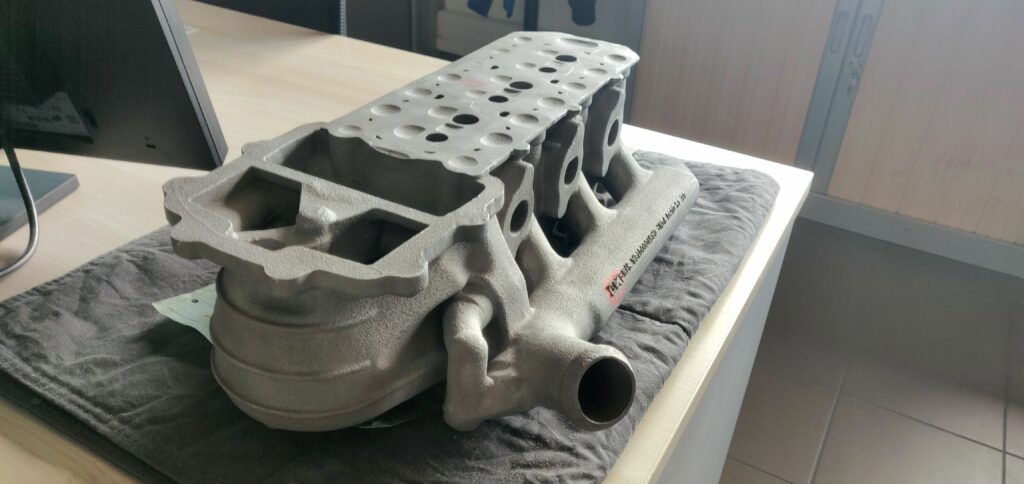
Foundry
As indicated, DE’s foundry today consists of a 2400 m² facility, in which the 100 TD2’s cylinder head, crankcase, turbocharger manifold and various subsystem covers (including that for the water pump) are produced, as are a range of other parts that include production components and demonstrators for contracts signed with non-Trident customers.
Sébastien Beaume, foundry methods office manager at DE tells us, “The original 600 m² facility was optimised only for making prototypes and, honestly, was somewhat disorganised and unergonomic, unlike our new, modern foundry that is highly sanitised, and organised for workflows and traceability, and so enables high volume part production much better.
“Additionally, the machinery and control systems throughout are more modern than those we possessed previously, with several qualifications from our main customers, including Safran Group and Liebherr Aerospace.”
Chief among the modernised equipment are two low-pressure, sand-casting furnaces. Previously, DE would gravity-cast its cylinder heads from aluminium, and its water pump cover from magnesium; however, low-pressure casting enables a more controlled dispensation speed of liquid metals into the mould than gravity-casting does, with that speed being a function of the computer-controlled pressure inside the furnace.
“Gravity-casting essentially means just pouring metal into a mould from atop a ladder; the higher up and safer from the metal you are, the more the metal picks up velocity on the way down, increasing problems of oxidisation and porosity in the resulting part,” Beaume says.
“You can reduce those problems by designing better pouring channels, but it’s much easier to repeatedly produce good parts daily with this controlled low-pressure casting. Gravity-casting also requires very big moulds that are complex to assemble, and a costly ratio of poured material versus the weight of the part: maybe 2.5x the weight of the finished part, whereas low pressure casting needs just 1.5-1.8x the weight of the final part.”
Beaume illustrates this through CAD diagrams of the gravity-cast 100 TD2 cylinder head, with its mould featuring complex pouring channels for uniform delivery of liquid metal across the part, meticulous use of risers to prevent cavities forming owing to metal shrinkages and many chillers for speed solidification at strategic points.
By comparison, DE’s liquid-casting mould has fewer and simpler channels, and Beaume notes that significantly less metal must be poured to form the head. Additionally, exposure of the chillers enables them to be sprayed with water, making them cool the metal more effectively and enabling better mechanical characteristics in the resulting cylinder head.
Choosing a low-pressure furnace compatible with sand-casting has also empowered DE to invest in sand core 3D printers for rapid, cost-optimised mould manufacturing. DE’s current core and sand mould printing machine is an S-Max from ExOne, which can produce (for example) up to 14 cylinder head moulds at a time, or any single mould with maximum dimensions of 70 x 180 x 100 cm, with a typical production time of 20 hours (down from 30 hours, following the recent acquisition of a modern printer head).
“Sand-casting things like bosses and mounting points for the turbo and alternator systems helps us to really tightly integrate customised electrification and altitude requirements, with integral sensor bosses or signal lines as needed for their data usage, and without changing the core design or qualification of the core engine,” Delaporte notes.
“Theoretically, we could very quickly prototype and iterate designs where we have two alternators, or a single-stage turbo without the low-pressure stage – the latter would even save weight because we’d only need half the standard intercooler. And then we can make different cooling packs, variable pitch propeller integrations and all kinds of other customisations.”
Simulation is also vital to every unit produced in the foundry. The first room past the foundry entrance is DE’s casting simulation office, where six engineers work (mostly with VisualCAST and CATIA V5) to adapt part geometries and metal feeding systems, and minimise development cycles, such that the first part poured in a new batch or prototyping round is of sufficient quality to be delivered to the customer.
Beyond the simulation and core printer offices is a pair of core blower machines that produce sand cores in a process similar to compression moulding, using tooling assemblies made from parts cut in DE’s machining facility to mould white sand cores, as and when more sand cores (or variations thereof) are needed than can be provided by the core printer.

After these stages is a mould assembly zone, where quality-validated moulds are fitted with chillers and risers as needed, and then taken beyond to the casting area. There, one first finds gravity-casting systems, as well as ladders safety-rated for engineers to pour 10-20 kg of metal at a time into the fitted moulds, with the low pressure-casting systems further down, together with preheating furnaces for preparing metals before they are drawn into the low-pressure foundries for melting.
“After placing the mould above the low-pressure system’s tube, we select the desired casting program at a nearby computer, which controls the pressures and liquid flows based directly on the simulations formed in our simulation office, in a way that avoids turbulent velocities and oxidisation, perfectly repeating the procedure each time,” Baume says.
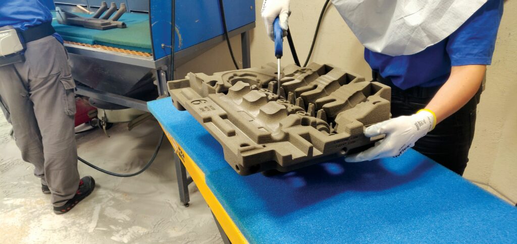
After cooling, hard toolings can be unscrewed and debonded to free the part. However, the sand moulds must be broken manually, typically first using a vibration table to weaken them uniformly without cracking or scratching the parts (and hence breaching aero cosmetic requirements), before smaller, handheld tools are then used to break the moulds. A low-temperature furnace is also available for breaking-down sand mould resins overnight without shocking metal parts.
Past the mould breaking stages, one also finds a Carlo Banfi shot blasting machine that provides aesthetic surface finishing for cast parts, and some semi-automated heat treatment furnaces from Thermal Sat for enhancing mechanical integrity in some aluminium parts.
A vacuum-casting machine for magnesium part production is situated in an adjoining room for safety reasons, functioning with similar principles to the low-pressure casting (using CO2 or argon to displace oxygen and prevent the violent reaction of heated magnesium with oxygen). As of writing, these are used only for the sump, oil tank and water pump cover, although DE is working on several magnesium part demonstrators with great potential to improve strength-to-weight in the Trident engines and other powertrains.
Machine workshop
DAS’s machining facility provides cutting, drilling, lathe-turning, and both cylindrical- and surface-grinding of metal components (both on billet or cast parts from the foundry), as well as all programming of the CNC machines behind those processes.
In the facility’s programming office, DAS analyses new part designs to determine through simulations how best to fasten them within the machines, and to establish the tooling, processes and control programs that should be applied to achieve the desired finished part, generally relying on TopSolid for CAD and Vericut for digital twinning of machines.
“Simulating the machines’ movements is critical, first to protect the parts, and then to protect the machines. If a tool contacts a part with a certain angle and speed, it can be very damaging for the machine – both its mechanical and its sensing systems – especially depending on the strength or vibrational properties of the material you’re trying to cut,” Delaporte says.
The personnel in this office also define inspection processes for ascertaining whether parts pass quality standards, including EN 9100 first article inspections to affirm that correct dimensions, roundness, material conditions and other parameters have been achieved.
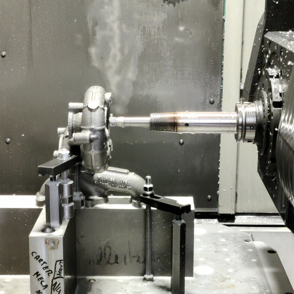
Moving from the office onto the machining floor, one encounters preliminary lathe-cutting machines, used (as of our visit) for removing residual stainless steel material from the turbocharger manifolds’ casting channels, accurate to 0.2-0.3 mm.
“The turbo manifolds will be grinded to a finer finish later on, but the unnecessary metal is cut during this preliminary stage to prevent deformations that could otherwise form if left to the more precise machines,” Delaporte adds.
Continuing through the facility, Danielson has a pair of Heller 5-axis milling machines: one used for precision-machining of the 100 TD2’s cylinder heads from the foundry, and the other used for producing metal tooling. An adjacent area features benches and tools for manual cutting and grinding, and for removal of sharp edges, engravings and other individual unit processes.
Next, a Gildemeister CTX gamma 1250 TC provides controlled (and simultaneous) turning and milling of complex, asymmetric parts, saving time on moving such parts between multiple different machines, or assembling and bonding them from multiple sections.
“We produce the Trident engines’ crankshafts in this machine, because its eccentric turning functionality enables the boring of rod bearing journals and other rounded features that sit off from the axis of rotation, covering 97% of the work needed to turn a 100 kg block into a 3-4 kg crankshaft,” Delaporte explains.
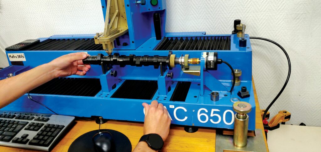
Camshaft production follows generally similar stages to the crankshaft, going through preliminary machining from billet, then heat treatment and quenching, followed by a definitive machining round, final grinding to obtain the right cam profiles, and then a DLC coating might be applied to reduce friction and optimise fuel efficiency.
“Most of our machines are semi-automated, but most recently, we’ve also added Heller’s Fastem robotic arm system. It can take finished parts out of the two CNC machines adjacent to it, and replace them with the next item to be worked, so those two machines can keep working through nights and weekends without operators,” Delaporte says. “It’s a huge help for increasing our capacity for Trident engines and other ordered parts.”
In the machining workshop’s QC centre, one first finds a proprietary camshaft inspection machine developed in-house, in which an installed camshaft is measured for angular position while a height-sensing tool runs atop each lobe, one at a time, to profile each lobe accurately and gauge its compliance with the CAD profile.
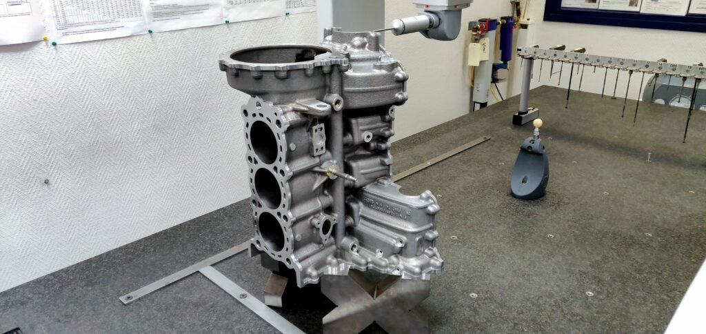
Two coordinate measuring machines (CMMs) in the room provide automated validation of various engine parts. As of our visit, a Brown & Sharpe Mistral machine was checking a customer’s cylinder head (delivered as part of an engine that had reached its 500 hour TBO), to check for wear and deformations.
The other CMM was inspecting a crankcase to ensure it had been correctly machined – particularly the crankshaft bore, being complex to machine owing to it having two-part (steel and aluminium) bearing caps – and was ready to be sent for plasma coating of its cylinders by Oerlikon.
Testing
A wide array of testing cells and benches are distributed across Danielson’s facilities to validate and characterise new systems, beginning with a containerised propeller testing cell, used for acceptance test procedures of either new engine customisations or engines undergoing overhauls.
“Before sending either such engine to a customer, we run it in one of these cells with a propeller fitted for five hours, including a power curve of 20-30 minutes, and then run telemetry analyses and visual checks of ancillaries to ensure that everything is in correct working order,” Delaporte says.
“We can also connect electrical loads to the alternator, to check that it functions correctly in supplying power for the kinds of loads that the aircraft will place upon it,” Delaporte adds.
For more rigorous environmental testing, Danielson has constructed a separate building with two aerotherm cells. The rooms – each roughly 700 m3 – can be heated up to 55 C to determine how an engine or vehicle can be thermally managed in such conditions.
A dyno bench is installed in each aerotherm cell, enabling engines to be run and their cooling systems gauged. They can also be cycled from ambient temperatures to 55 C, and a rail atop each room can dispense water vapour to simulate varying levels of humidity.
Danielson also has four dyno testing cells, each of which enables integration of enough sensors to operationally validate the full range of performance of an engine or gearbox. As Vincent Heurtier, directeur géneral of Groupe Danielson’s validation team tells us, “Such measurements typically enable identification of an engine or gearbox’s maximum torque, speed, power, oil temperature and oil pressure, with all data being recorded via the computers outside of each cell.”
Tests in these cells can be automated, to enable endurance or fatigue testing, or to ease repetitive processes such as the CS-E 100 startups-and-stops test mentioned earlier.
Future
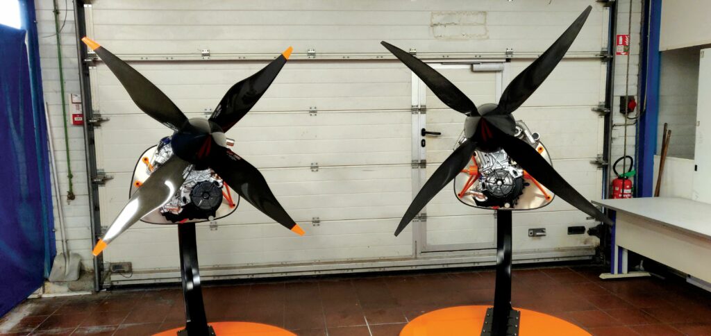
While Groupe Danielson has no shortage of projects, the successful commercialisation of the 100 TD2 is spurring the company to focus its r&d on three other engines in the Trident series.
Two of these are four-cylinder variants of the 100 TD2 design, conceived prior to our earlier feature but now under active development thanks to the tacit validation gained through the i3’s flight hours. In particular, the smaller of these two i4s – the 140 TD2 – is essentially a 100 TD2 with a fourth cylinder of identical bore and stroke added, making for 1.4 L displacement and 140 hp max power.
The larger i4 is the 200 TD2, with four cylinders of 85 x 97 mm bore and stroke, thus displacing 2.2 L and outputting up to 200 hp. As of writing, it has a dry weight of 115 kg (compared with the 140 TD2’s 95 kg).
“We say the 140 TD2 has a TRL of 5, simply because that indicates the specific work on it so far, but so much of it uses exactly the same architecture and parts as the 100 TD2 that it’s effectively all proven technology,” Delaporte says.
“The 180 TD2 will take more work. It has a bigger displacement, to make more power, and that then needs a new turbocharging system design, optimisation of the fuelling system, a new crankshaft and so on.”
Additionally, preliminary designs are in the works for an opposed-twin Trident 50SD with a target power output of 50-65 hp.
With all these new powertrains planned, and its production capacity more than ready for prototyping, validating and certifying customer engines as needed, one can soon expect the Danielson brand to once again take hold across France, Europe and beyond.
Key specifications
Trident 100 TD2
I3
Compression ignition
Two-stage turbocharging
Diesel and kerosenes
Water- and oil-cooling
1.28:1 gearbox
Mechanical direct fuel injection
Liner-less, plasma-sprayed
bore coating
Chain-driven single overhead camshaft
76.0 x 80.5 mm = 1095.6 cc
Dry weight: 75 kg
Installed weight (including complete cooling systems): 120 kg
Maximum power: 74.6 kW (100 hp)
Maximum speed: 3600 rpm
Compression ratio: 15:1
Cruise SFC: 230 g/kWh
TBO: 500 hours
Some key suppliers
Casting, machining, and welding: In-house
Sand mould 3D printer: ExOne
CFD & wind tunnel R&D: Aero Concept Engineering
Cylinder head covers (and additional carbon parts): SC Aero
Fuel pumps and gascolators: Andair
Hot isostatic pressing: Bodycote
Plasma coatings: Oerlikon MetCo
Propellers: Duc Hélices
Zinc plating, anodising and other services: Prebet
UPCOMING EVENTS


